Series 3700A System Switch/Multimeter - User's Manual 3700AS-900-01 Rev. B / July 2016
←
→
Page content transcription
If your browser does not render page correctly, please read the page content below
www.tek.com/keithley

Series 3700A System Switch/Multimeter
User’s Manual
3700AS-900-01 Rev. B / July 2016

*P3700AS-900-01B*
 3700AS-900-01B

A Greater M easure of Confidence
                                   A T ektr onix Company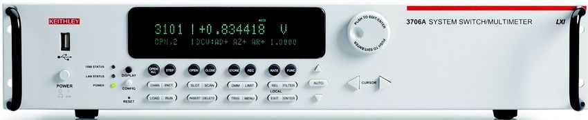
Series 3700A

                   System Switch/Multimeter
                                User's Manual

                                 © 2016, Keithley Instruments
                                   Cleveland, Ohio, U.S.A.
                                      All rights reserved.
Any unauthorized reproduction, photocopy, or use of the information herein, in whole or in part,
        without the prior written approval of Keithley Instruments is strictly prohibited.
  All Keithley Instruments product names are trademarks or registered trademarks of Keithley
 Instruments. Other brand names are trademarks or registered trademarks of their respective
                                          holders.

                    Document number: 3700AS-900-01 Rev. B / July 2016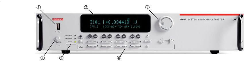
Safety precautions
The following safety precautions should be observed before using this product and any associated instrumentation. Although
some instruments and accessories would normally be used with nonhazardous voltages, there are situations where hazardous
conditions may be present.
This product is intended for use by qualified personnel who recognize shock hazards and are familiar with the safety precautions
required to avoid possible injury. Read and follow all installation, operation, and maintenance information carefully before using
the product. Refer to the user documentation for complete product specifications.
If the product is used in a manner not specified, the protection provided by the product warranty may be impaired.

The types of product users are:
Responsible body is the individual or group responsible for the use and maintenance of equipment, for ensuring that the
equipment is operated within its specifications and operating limits, and for ensuring that operators are adequately trained.
Operators use the product for its intended function. They must be trained in electrical safety procedures and proper use of the
instrument. They must be protected from electric shock and contact with hazardous live circuits.
Maintenance personnel perform routine procedures on the product to keep it operating properly, for example, setting the line
voltage or replacing consumable materials. Maintenance procedures are described in the user documentation. The procedures
explicitly state if the operator may perform them. Otherwise, they should be performed only by service personnel.
Service personnel are trained to work on live circuits, perform safe installations, and repair products. Only properly trained
service personnel may perform installation and service procedures.

Keithley Instruments products are designed for use with electrical signals that are measurement, control, and data I/O
connections, with low transient overvoltages, and must not be directly connected to mains voltage or to voltage sources with high
transient overvoltages. Measurement Category II (as referenced in IEC 60664) connections require protection for high transient
overvoltages often associated with local AC mains connections. Certain Keithley measuring instruments may be connected to
mains. These instruments will be marked as category II or higher.
Unless explicitly allowed in the specifications, operating manual, and instrument labels, do not connect any instrument to mains.
Exercise extreme caution when a shock hazard is present. Lethal voltage may be present on cable connector jacks or test
fixtures. The American National Standards Institute (ANSI) states that a shock hazard exists when voltage levels greater than
30 V RMS, 42.4 V peak, or 60 VDC are present. A good safety practice is to expect that hazardous voltage is present in any
unknown circuit before measuring.
Operators of this product must be protected from electric shock at all times. The responsible body must ensure that operators
are prevented access and/or insulated from every connection point. In some cases, connections must be exposed to potential
human contact. Product operators in these circumstances must be trained to protect themselves from the risk of electric shock. If
the circuit is capable of operating at or above 1000 V, no conductive part of the circuit may be exposed.

Do not connect switching cards directly to unlimited power circuits. They are intended to be used with impedance-limited
sources. NEVER connect switching cards directly to AC mains. When connecting sources to switching cards, install protective
devices to limit fault current and voltage to the card.
Before operating an instrument, ensure that the line cord is connected to a properly-grounded power receptacle. Inspect the
connecting cables, test leads, and jumpers for possible wear, cracks, or breaks before each use.
When installing equipment where access to the main power cord is restricted, such as rack mounting, a separate main input
power disconnect device must be provided in close proximity to the equipment and within easy reach of the operator.
For maximum safety, do not touch the product, test cables, or any other instruments while power is applied to the circuit under
test. ALWAYS remove power from the entire test system and discharge any capacitors before: connecting or disconnecting
cables or jumpers, installing or removing switching cards, or making internal changes, such as installing or removing jumpers.

Do not touch any object that could provide a current path to the common side of the circuit under test or power line (earth)
ground. Always make measurements with dry hands while standing on a dry, insulated surface capable of withstanding the
voltage being measured.
For safety, instruments and accessories must be used in accordance with the operating instructions. If the instruments or
accessories are used in a manner not specified in the operating instructions, the protection provided by the equipment may be
impaired.
Do not exceed the maximum signal levels of the instruments and accessories. Maximum signal levels are defined in the
specifications and operating information and shown on the instrument panels, test fixture panels, and switching cards.
When fuses are used in a product, replace with the same type and rating for continued protection against fire hazard.
Chassis connections must only be used as shield connections for measuring circuits, NOT as protective earth (safety ground)
connections.
If you are using a test fixture, keep the lid closed while power is applied to the device under test. Safe operation requires the use
of a lid interlock.

If a    screw is present, connect it to protective earth (safety ground) using the wire recommended in the user documentation.

The     symbol on an instrument means caution, risk of danger. The user must refer to the operating instructions located in the
user documentation in all cases where the symbol is marked on the instrument.

The      symbol on an instrument means caution, risk of electric shock. Use standard safety precautions to avoid personal
contact with these voltages.

The       symbol on an instrument shows that the surface may be hot. Avoid personal contact to prevent burns.

The       symbol indicates a connection terminal to the equipment frame.

If this    symbol is on a product, it indicates that mercury is present in the display lamp. Please note that the lamp must be
properly disposed of according to federal, state, and local laws.
The WARNING heading in the user documentation explains dangers that might result in personal injury or death. Always read
the associated information very carefully before performing the indicated procedure.
The CAUTION heading in the user documentation explains hazards that could damage the instrument. Such damage may
invalidate the warranty.
Instrumentation and accessories shall not be connected to humans.
Before performing any maintenance, disconnect the line cord and all test cables.
To maintain protection from electric shock and fire, replacement components in mains circuits — including the power
transformer, test leads, and input jacks — must be purchased from Keithley Instruments. Standard fuses with applicable national
safety approvals may be used if the rating and type are the same. The detachable mains power cord provided with the
instrument may only be replaced with a similarly rated power cord. Other components that are not safety-related may be
purchased from other suppliers as long as they are equivalent to the original component (note that selected parts should be
purchased only through Keithley Instruments to maintain accuracy and functionality of the product). If you are unsure about the
applicability of a replacement component, call a Keithley Instruments office for information.
Unless otherwise noted in product-specific literature, Keithley instruments are designed to operate indoors only, in the following
environment: Altitude at or below 2,000 m (6,562 ft); temperature 0 °C to 50 °C (32 °F to 122 °F) ; and pollution degree 1 or 2.
To clean an instrument, use a damp cloth or mild, water-based cleaner. Clean the exterior of the instrument only. Do not apply
cleaner directly to the instrument or allow liquids to enter or spill on the instrument. Products that consist of a circuit board with
no case or chassis (e.g., a data acquisition board for installation into a computer) should never require cleaning if handled
according to instructions. If the board becomes contaminated and operation is affected, the board should be returned to the
factory for proper cleaning/servicing.
Safety precaution revision as of March 2016.
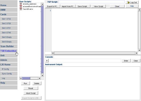
Table of Contents
Introduction ............................................................................................................... 1-1
      Welcome .............................................................................................................................. 1-1
      Contact information .............................................................................................................. 1-1
      Extended warranty ............................................................................................................... 1-1
      Introduction to this manual ................................................................................................... 1-2
      Product documentation, drivers, and software .................................................................... 1-2
      Measuring capabilities.......................................................................................................... 1-3
      Safety precautions for connections ...................................................................................... 1-3

Using the front-panel interface ................................................................................ 2-1
      Introduction .......................................................................................................................... 2-1
      Series 3700A front panel overview ...................................................................................... 2-2
              (1) The USB port ....................................................................................................................... 2-3
              (2) The display .......................................................................................................................... 2-3
              (3) The navigation wheel ........................................................................................................... 2-5
              (4) The POWER key ................................................................................................................. 2-5
              (5) The status lights................................................................................................................... 2-5
              (6) The setup and control keys .................................................................................................. 2-5
      Channel identification ........................................................................................................... 2-7
              Matrix card channel specifiers ................................................................................................... 2-7
              Analog backplane relay channel specifiers ............................................................................... 2-7
              Multiplexer, digital I/O, totalizer, and DAC channel specifiers ................................................... 2-8
      Operating a channel from the front panel ............................................................................ 2-8
      Viewing the close or open status of a channel .................................................................... 2-9
      Emulate a Model 3706 ....................................................................................................... 2-10
      Channel patterns ................................................................................................................ 2-10
              Create a channel pattern ......................................................................................................... 2-10
              Exercise: Create channel pattern "TEST01" from closed channels......................................... 2-11
              Performing close and open operations on channel patterns ................................................... 2-11
              Exercise: Close channel pattern "TEST01" from the front panel ............................................. 2-12
              Set up row, column, and channel labels.................................................................................. 2-12
              Exercise: Create a channel label using the front panel ........................................................... 2-12
      Front-panel scanning ......................................................................................................... 2-12
              Exercise: Perform a scan and save to a USB flash drive ........................................................ 2-13
      Taking measurements without a switch card ..................................................................... 2-14
              Pseudocards ........................................................................................................................... 2-14
              Using the analog backplane connector to take measurements ............................................... 2-14

Using the web interface ............................................................................................ 3-1
      Introduction .......................................................................................................................... 3-1
      Connecting to the instrument web interface......................................................................... 3-1
      Web interface home page .................................................................................................... 3-2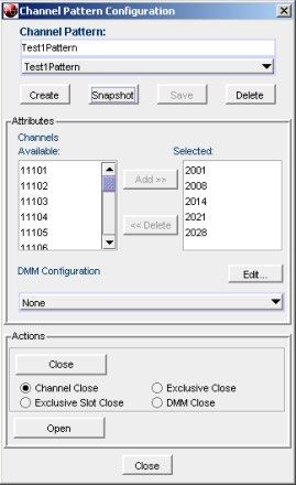
Table of Contents                                                                                    Series 3700A System Switch/Multimeter User's Manual

      Log in to the instrument........................................................................................................ 3-2
      Card pages ........................................................................................................................... 3-3
              Open and close channels from the card pages ......................................................................... 3-4
              Set up channel patterns from the web interface ........................................................................ 3-7
      Scan Builder page ................................................................................................................ 3-8
              Create a scan list ...................................................................................................................... 3-9
              Run the scan ............................................................................................................................. 3-9
              Stop the scan ............................................................................................................................ 3-9
              Clear the scan list from the web interface ............................................................................... 3-10
              Set up simple triggers ............................................................................................................. 3-10
      TSB Embedded .................................................................................................................. 3-11
              Create a script using TSB Embedded ..................................................................................... 3-11

Applications .............................................................................................................. 4-1
      About the Series 3700A examples ....................................................................................... 4-1
      Scanning examples .............................................................................................................. 4-1
              Example: Scan the card with no measurement (switch-only) .................................................... 4-2
              Example: Scan the card and take measurements ..................................................................... 4-3
              Example: Take 4-wire ohm measurements using a background scan ...................................... 4-4
              Example: Scan, measure, and store ......................................................................................... 4-5
              Example: Optimize scan for speed............................................................................................ 4-6
              Example: Fast DC volt measurement........................................................................................ 4-7
              Example: AC volts Autodelay Once script ................................................................................. 4-9
              Example: Fast alternating scan, DC volts, and two-wire ohms................................................ 4-11
              Example: Thermocouple temperature measurement from the front panel .............................. 4-12
              Example: Thermocouple measurement through the remote interface..................................... 4-13
      Example: TSP-Link and interactive triggers ....................................................................... 4-13
              Set up communication............................................................................................................. 4-14
              Logical block diagram of test connections............................................................................... 4-15
              Example program code ........................................................................................................... 4-15
              Program code to run the test ................................................................................................... 4-18
      Example: Using the scanning and triggering model .......................................................... 4-18
              Set up communication............................................................................................................. 4-19
              Example program code ........................................................................................................... 4-20
              Program code to run the test ................................................................................................... 4-22
              Using background scans for longer scan lists ......................................................................... 4-23
      Example: IEEE-1588 in Series 3700A-based systems ...................................................... 4-24
              Scheduling alarms................................................................................................................... 4-24
              Scheduling alarms on a stand-alone Series 3700A................................................................. 4-25
      Example: External DMM and switch triggering .................................................................. 4-26
      Example: DMM buffer statistics with interactive operation ................................................ 4-29
      Example: Commonside ohm measurement with Model 3721 ........................................... 4-31

Troubleshooting FAQs ............................................................................................. 5-1
      About this section ................................................................................................................. 5-1
      Need different line frequency or voltage .............................................................................. 5-1
      Switch matrix does not recognize my card .......................................................................... 5-1
      The internal web page of the instrument is not accessible .................................................. 5-2
Series 3700A System Switch/Multimeter User's Manual Table of Contents
Error when I try to close a channel ...................................................................................... 5-2
Switch relays will not close .................................................................................................. 5-3
Save the present state of the instrument ............................................................................. 5-3
Where can I get the LabVIEW driver? ................................................................................. 5-3
Why can't the Series 3700A read my USB flash drive? ....................................................... 5-3
Next steps ............................................................................................................................ 5-1
Index ........................................................................................................................... I-1Section 1
Introduction
In this section:
Welcome .................................................................................. 1-1
Contact information .................................................................. 1-1
Extended warranty ................................................................... 1-1
Introduction to this manual ....................................................... 1-2
Product documentation, drivers, and software ......................... 1-2
Measuring capabilities .............................................................. 1-3
Safety precautions for connections .......................................... 1-3
Welcome
Thank you for choosing a Keithley Instruments product. The Series 3700A System Switch/Multimeter
features scalable, instrument grade switching and multi-channel measurement solutions that are
optimized for automated testing of electronic products and components. The Series 3700A includes
four versions of the Model 3706A system switch mainframe, along with a growing family of plug-in
switch and control cards. When the Model 3706A mainframe is ordered with the high performance
multimeter, you receive a tightly-integrated switch and measurement system that can meet the
demanding application requirements in a functional test system or provide the flexibility needed in
stand-alone data acquisition and measurement applications.
Contact information
If you have any questions after you review the information in this documentation, please contact your
local Keithley Instruments office, sales partner, or distributor. You can also call the corporate
headquarters of Keithley Instruments (toll-free inside the U.S. and Canada only) at 1-800-935-5595,
or from outside the U.S. at +1-440-248-0400. For worldwide contact numbers, visit the Keithley
Instruments website (http://www.tek.com/keithley).
Extended warranty
Additional years of warranty coverage are available on many products. These valuable contracts
protect you from unbudgeted service expenses and provide additional years of protection at a fraction
of the price of a repair. Extended warranties are available on new and existing products. Contact your
local Keithley Instruments office, sales partner, or distributor for details.Section 1: Introduction Series 3700A System Switch/Multimeter User's Manual
Introduction to this manual
This manual provides detailed tutorials to help you achieve success with your Keithley Instruments
Series 3700A System Switch/Multimeter. In addition, this manual provides the basics of the two
simplest Series 3700A interfaces, the front panel and the web interface, to familiarize you with the
instrument. You can also familiarize yourself with the instrument by running the examples in this
manual that are relevant to your intended use and to the equipment you are using.
Some of the examples in this manual may use unfamiliar commands and concepts. For detailed
information about these, refer to the Series 3700A Reference Manual.
Product documentation, drivers, and software
The Series 3700A Quick Start Guide, User's Manual, Reference Manual, and Switching and Control
Cards Reference Manual are available for download in PDF format on the Keithley Downloads web
page (http://www.tek.com/downloads).
• Quick Start Guide: Provides unpacking instructions, describes basic connections, and reviews
basic operation information. If you are new to Keithley Instruments equipment, refer to the Quick
Start Guide to take the steps needed to unpack, set up, and verify operation.
• User's Manual: Provides application examples. If you need a starting point to begin creation of
applications, refer to the User's Manual for a variety of specific examples.
• Reference Manual: Includes advanced operation topics and maintenance information.
Programmers looking for a command reference, and users looking for an in-depth description of
the way the instrument works (including troubleshooting and optimization), should refer to the
Reference Manual.
• Switching and Control Cards Reference Manual: Contains information specific to the switch
cards that can be used with the Series 3700A.
• Additional product information: The product data sheets, product specifications, and
accessories information.
Additional drivers and software are available for download from the Keithley Downloads web page
(http://www.tek.com/downloads).
Test Script Builder (TSB) Integrated Development Environment: This software provides an
environment to develop a test program and the ability to load the test program onto the instrument.
Running a program loaded on the instrument eliminates the need to send individual commands from
the host computer to the instrument when running a test.
• The Model 3706A TSB Add-in: A software tool you can use to create, modify, debug, and store
®
Test Script Processor (TSP ) test scripts.
• IVI Instrument Driver: Driver for National Instruments LabVIEW™, and related release notes.
• J2SE™ Runtime Environment: Web browser plug-in required to run the web applications that
are available through the instrument web interface.
• Keithley I/O layer and release notes.
• Keithley LXI Discovery Browser.
1-2 3700AS-900-01 Rev. B / July 2016Series 3700A System Switch/Multimeter User's Manual Section 1: Introduction
Measuring capabilities
The basic measurement capabilities of Series 3700A systems are summarized in the following figure.
Figure 1: DMM measurement capabilities
Safety precautions for connections
Connection information for switching cards is intended for qualified service personnel. Do
not attempt to connect DUT or external circuitry to a switching card unless qualified to do
so.
To prevent electric shock that could result in serious injury or death, comply with these
safety precautions:
Before making or breaking any connections to the switching card, make sure the Series
3700A is turned off and power is removed from all external circuitry.
Do not connect signals that will exceed the maximum specifications of any installed
switching card.
If both the rear analog backplane connector of the Series 3700A and the switching card
terminals are connected at the same time, the test lead insulation must be rated to the
highest voltage that is connected. For example, if 300V is connected to the analog
backplane connector, the test lead insulation for the switching card must also be rated for
300V.
Dangerous arcs of an explosive nature in a high-energy circuit can cause severe personal
injury or death if contacted. If the multimeter is connected to a high-energy circuit when set
to a current range, low resistance range, or any other low-impedance range, the circuit is
virtually shorted.
Dangerous arcing can result (even when the multimeter is set to a voltage range) if the
minimum voltage spacing is reduced in the external connections. For details about how to
safely make high energy measurements, see High-energy circuit safety precautions in the
Series 3700A Reference Manual. As described in the International Electrotechnical
Commission (IEC) Standard IEC 664, the Series 3700A is Installation Category I and must
not be connected to mains.
3700AS-900-01 Rev. B / July 2016 1-3Section 2
Using the front-panel interface
In this section:
Introduction .............................................................................. 2-1
Series 3700A front panel overview........................................... 2-2
Channel identification ............................................................... 2-7
Operating a channel from the front panel ................................. 2-8
Viewing the close or open status of a channel ......................... 2-9
Emulate a Model 3706 ........................................................... 2-10
Channel patterns .................................................................... 2-10
Front-panel scanning ............................................................. 2-12
Taking measurements without a switch card.......................... 2-14
Introduction
Before starting this section, complete the tasks outlined in the Series 3700A Quick Start Guide. Once
you have completed those tasks, read this section, which provides enough basic information about
the Model 3706A front-panel interface to work through the examples provided in this manual.
The Keithley Instruments Models 3706A and 3706A-S front panels contain the following items:
• (1) The USB port (on page 2-2)
• (2) The display (on page 2-3)
• (3) The navigation wheel (on page 2-5)
• (4) The POWER key (on page 2-5)
• (5) The status lights (on page 2-5)
• (6) The setup and control keys (on page 2-5)
For these models, you can use the keys, display, and the navigation wheel to access, view, and
edit the menu items and set values.
The Models 3706A-NFP and 3706A-SNFP front panels do not have a display, navigation wheel, and
setup and control keys. These models are configured and controlled through a remote interface. For
more information, see Using the web interface (on page 3-1) in this manual, and refer to the Series
3700A Reference Manual for detailed information about instrument programming and remote
commands.Section 2: Using the front-panel interface Series 3700A System Switch/Multimeter User's Manual
Series 3700A front panel overview
The Series 3700A includes several models that support different features. The following figures show
the front panels of each of the models; a brief description of the features follows the figures.
For more detailed information about the Model 3706A front panel, see the “General operation” section
in the Series 3700A Reference Manual.
Figure 2: Model 3706A with DMM front panel
Figure 3: Model 3706A-S front panel (no DMM)
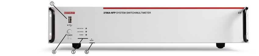
Figure 4: Models 3706A-NFP (with DMM) and 3706A-SNFP (no DMM) front panel
2-2 3700AS-900-01 Rev. B / July 2016Series 3700A System Switch/Multimeter User's Manual Section 2: Using the front-panel interface
(1) The USB port
Use the front-panel USB port to connect a USB flash drive. The USB flash drive can be used to
store reading buffer data, scripts, and user setup options.
(USB port)
(2) The display
During setup, the display shows menu choices that you can use to configure the instrument. See
"Menu overview" in the Series 3700A Reference Manual for more information about Series 3700A
menus.
During operation, the display provides information about the selected channel, channel pattern,
channel state, and errors. It also shows the control status (local or remote). If REM is displayed, the
instrument is presently controlled through a remote interface (GPIB, LAN, or USB). If REM is not
displayed, control is through the front panel. The following figure shows an example of the Series
3700A during operation.
Figure 5: Series 3700A display during operation
Series 3700A display during operation
1 Active channel (slot 1, channel 004)
2 Channel state (open, 2-pole operation)
3 Present state of the DMM attributes for displayed channel:
• The 4-WΩ and autorange are enabled
• Dry-circuit ohms is disabled (DRY-)
• Offset compensation is off (OC-)
For detailed descriptions of the DMM attribute symbols, see the table labeled "DMM
attribute symbols" in the "Front-panel operation" topic in the Series 3700A Reference
Manual
4 Arrow indicating that more menu items exist; turn the navigation wheel to the left or
right to see the additional items.
5 The 4-WΩ and autorange is enabled
6 Indicates the instrument is in remote operation rather than local operation
3700AS-900-01 Rev. B / July 2016 2-3Section 2: Using the front-panel interface Series 3700A System Switch/Multimeter User's Manual
The table below lists the display indicators and what they mean.
Indicator Meaning
AUTO: Measure autorange is selected
EDIT: Instrument is in the editing mode
ERR: Questionable reading or invalid calibration step
FILT: Digital filter is enabled
LSTN: Instrument is addressed to listen
MATH: Enabled for mX+b, percent, or reciprocal (1/X) calculation
REL: Relative mode is enabled
REM: Instrument is in remote mode
SRQ: Service request is asserted
TALK: Instrument is addressed to talk
TRIG: Instrument is processing a front-panel reading request
4W: Four-wire resistance or RTD temperature reading
* (asterisk): Readings are being stored in the buffer
The bottom left line of the display contains the DMM attribute symbols. The symbols that appear are
dependent on whether the attribute exists for the selected function. The following table indicates the
DMM attribute symbols that may appear on the front panel. If the symbol has a value associated with
it, the third column in the table indicates the value definition.
DMM attribute symbols
Front-panel DMM attribute Symbol Values
range R= AUTO or n, where n equals the range
nplc N= n, where n equals the NPLC
auto delay AD + for ON, 1 for ONCE, or 0 for OFF
auto zero AZ + for ON or – for OFF
line sync LS + for ON or – for OFF
limit LIM + for a limit enabled or – for limits disabled
detector bandwidth DBW 3, 30, or 300
threshold THR= n, where n indicates the threshold
aperture A= n, where n indicates the aperture setting
dry circuit DRY + for ON or – for OFF
offset compensation OC + for ON or – for OFF
thermocouple sensor K K_T/C N/A
thermocouple sensor T T_T/C N/A
thermocouple sensor E E_T/C N/A
thermocouple sensor R R_T/C N/A
thermocouple sensor S S_T/C N/A
thermocouple sensor B B_T/C N/A
thermocouple sensor N N_T/C N/A
thermistor THRM N/A
three-wire RTD 3RTD N/A
4-wire RTD 4RTD N/A
simulated reference junction RJ_SIM N/A
internal reference junction RJ_INT N/A
external reference junction RJ_EXT N/A
2-4 3700AS-900-01 Rev. B / July 2016Series 3700A System Switch/Multimeter User's Manual Section 2: Using the front-panel interface
(3) The navigation wheel
Turn the navigation wheel to scroll to the desired menu option or to change the value of
the selected numeric parameter. Pressing the navigation wheel has the same
functionality as pressing the ENTER key.
When changing a multiple character value, such as an IP address or channel pattern
name, press the navigation wheel to enter edit mode, rotate the navigation wheel to
change the characters value as desired, but do not leave edit mode. Use the CURSOR
keys to scroll to the other characters and use the navigation wheel to change their value
as needed. Press the ENTER key when finished changing all the characters.
(4) The POWER key
POWER Power switch. The in position turns the Series 3700A on (I); the out position turns it off (O).
(5) The status lights
The Series 3700A has three status lights on the front panel.
The 1588 status light indicates 1588 operation. If this light is off, the 1588 feature is
disabled or improperly configured. If the light blinks at a one-second rate, the
instrument is the 1588 master. If the instrument is a slave, the light will not blink.
The LAN status light is lit when the instrument is connected through the local area
network (LAN) with no errors. If this is not lit, the instrument is not connected through
the LAN or there is a connection problem.
If you are using the web interface, the LAN Status light blinks when you click ID.
The POWER light is lit when power is applied to the instrument.
(6) The setup and control keys
The setup and control keys provide front panel control and configuration. The following figure
illustrates each key's location. The table following the figure contains a definition of each key. For
detailed information about front-panel keys, refer to the "Menu overview" topic in the Series 3700A
Reference Manual.
Figure 6: Model 3706A with DMM setup and control keys
3700AS-900-01 Rev. B / July 2016 2-5Section 2: Using the front-panel interface Series 3700A System Switch/Multimeter User's Manual
Key descriptions
Key Description
DISPLAY Toggles between the channel measure display, closed channels list, and the user
message mode
CONFIG Configures a function or operation
RESET Restores factory default LAN settings
OPEN ALL Opens all closed channels
STEP Steps through each step in a predefined scan list
OPEN Opens the selected channel or channel pattern
CLOSE Closes the selected channel or channel pattern
STORE Selects, clears, and saves reading buffer data and creates and deletes reading
buffers
REC Displays stored readings for selected reading buffer
RATE Sets measurement speed (fast, medium, or slow) for the active or selected
function
FUNC Changes to the next function in a factory-defined list of available DMM functions
CHAN If a channel is displayed, opens and closes channels; if a pattern is displayed,
switches to channel view
PATT If a pattern is displayed, manages, opens and closes, and resets patterns; if a
channel is displayed, changes to display a pattern
SLOT Displays information about the installed cards and the instrument, including
firmware revision, model name, and model number
SCAN Allows you to run, manage, view, and reset scan lists
DMM Opens the DMM ACTION menu
LIMIT Puts cursor in the compliance limit field for editing and selects the limit value to
edit
REL Controls relative measurements; allows baseline value to be subtracted from
reading
FILTER Enables or disables the digital filter; you can use this filter to reduce reading noise
LOAD Loads test for execution
RUN Runs the last selected user-defined test code
INSERT Appends the present channels to the scan list
DELETE Deletes channels or channel patterns from the scan list
TRIG Triggers readings
MENU Accesses the main menu, which can be used to configure instrument operation
EXIT (LOCAL) Cancels selection and backs out of the menu structure; also used as a LOCAL
key to take the instrument out of remote operation
ENTER Accepts the current selection or brings up the next menu option; pressing this key
is often the same as pressing the navigation wheel
AUTO Enables or disables autorange for the selected function
RANGE (up and Selects the next higher or lower measurement range on the measurement display
down arrows) for the selected function.
CURSOR Moves the cursor left or right for editing and scrolls through menu options
2-6 3700AS-900-01 Rev. B / July 2016Series 3700A System Switch/Multimeter User's Manual Section 2: Using the front-panel interface
Channel identification
Matrix card channel specifiers
The channels on the matrix cards are referred to by their slot, bank, row, and column numbers:
• Slot number: The number of the slot in which the card is installed.
• Bank number: The bank number, if used by your card. See your card documentation.
• Row number: The row number is either 1 to 8 or A to Z. See your card documentation.
Column number: Always two digits. For columns greater than 99, use A, B, C and so on to represent
10, 11, 12, …; the resulting sequence is: 98, 99, A0, A1, …, A8, A9, B0, B1, …
Matrix channel examples
Specifier Slot Bank Row Column
number number number number
1104 1 N/A 1 04
11104 1 1 1 04
1203 1 N/A 2 03
213A4 2 1 3 104
3112 3 N/A 1 12
62101 6 2 1 01
Analog backplane relay channel specifiers
The channels for slots with analog backplane relays are referred to by their slot, backplane, bank, and
relay numbers:
• Slot number: The number of the slot.
• Backplane number: Always 9.
• Bank number: The bank number, if used by your card. See your card documentation for detail.
• Analog backplane relay number: The number of the backplane relay. Typically 1 to 6. See your
card documentation for detail.
Backplane relay examples
Specifier Slot Backplane Bank Backplane relay
number number number number
1914 1 9 1 4
1922 1 9 2 2
2924 2 9 2 4
3916 3 9 1 6
3700AS-900-01 Rev. B / July 2016 2-7Section 2: Using the front-panel interface Series 3700A System Switch/Multimeter User's Manual
Multiplexer, digital I/O, totalizer, and DAC channel specifiers
The channels for multiplexer (MUX), digital I/O, totalizer, and digital to analog converter channels are
referred to by their slot and channel numbers:
• Slot number: The number of the slot in which the card is installed.
• Channel number: The number of the channel (always three digits).
Specifier Slot Channel
number number
1004 1 004
2050 2 050
3012 3 012
3003 3 003
2007 2 007
1020 1 020
Operating a channel from the front panel
Hot switching can dry-weld reed relays, causing them to always be on. Hot switching is
recommended only when external protection is provided.
You can perform operations on a single channel from the front panel.
To select a channel:
1. If the instrument is being controlled remotely, press EXIT to allow control from the front panel.
2. Press the navigation wheel to select the first digit of the channel specifier, which is the slot
number . The digit flashes, which indicates that it can be edited.
Figure 7: Select a channel from the Model 3706A front panel
2-8 3700AS-900-01 Rev. B / July 2016Series 3700A System Switch/Multimeter User's Manual Section 2: Using the front-panel interface
3. To change to a different slot number, turn the navigation wheel until the slot number you want is
displayed.
4. Press navigation wheel .
5. If your card supports banks, the next number you can select is the bank number. Set this as
needed using the navigation wheel .
6. Set the channel number (or rows and columns for installed matrix cards) as needed using the
navigation wheel .
7. The display shows the current state of the selected channel in the bottom row . In this example,
the channel is open and 2-pole (if you see : followed by a channel specifier, you selected a range;
press EXIT to return to the main display and reselect your channel).
Figure 8: Series 3700A selected channel state
To:
Close a channel without affecting any other channels: Select CLOSE.
Open the channel: Press OPEN.
Close a channel and open any other closed channels on the instrument: Select CHAN and
select EXCLOSE. Press ENTER to close the selected channels.
Close a channel and open any other closed channels on the slot that contains the selected
channel: Select CHAN, and then select EXSLOTCLOSE. Press ENTER to close the selected
channels.
Once a channel is selected, it is the selected channel for any subsequent front-panel operations.
Viewing the close or open status of a channel
Closed channels are shown separated by commas after the CLS: characters on the display of the
instrument. If no channels are closed, is displayed here. If the list of closed channels extends
past one screen, ... is displayed at the end of the line. Press DISPLAY to display the full list of
closed channels. Use the navigation wheel to scroll through the list. After viewing the list, press
DISPLAY twice to return to the main display.
Figure 9: Multiple closed channels
3700AS-900-01 Rev. B / July 2016 2-9Section 2: Using the front-panel interface Series 3700A System Switch/Multimeter User's Manual
Emulate a Model 3706
If you replace a Model 3706 with a Model 3706A in a system where computer drivers may be
querying the model, you may need to emulate a Model 3706. This can occur if you replace a Model
3706 with a Model 3706A in an existing system, or if you duplicate a system but use a Model 3706A
instead of a Model 3706.
When this is set to emulate a Model 3706, the model number is reported as a 3706 when you send a
request with a command such as localnode.model or *idn?. This allows drivers that query the
model number to continue to operate normally.
This setting is maintained through an instrument reset and through power cycles.
To emulate a Model 3706 using the front panel menus:
1. If the instrument is being controlled remotely, press EXIT to allow control from the front panel.
2. Press MENU.
3. Use navigation wheel to display and select EMULATION.
4. Select 3706.
5. Press ENTER.
You can also use the remote command localnode.emulation to set emulation.
All other Model 3706A behavior is the same. Emulation mode does not affect the changes to the
IEEE-1588 features or the response times that occurred with the update from the Model 3706 to the
Model 3706A.
Channel patterns
You can use channel patterns as a convenient way to refer to a group of switching channels and
backplane relays with a single alphanumeric name. When you perform close or open operations on a
channel pattern, only the channels and analog backplane relays that are in the channel pattern are
affected.
There is no speed difference when performing close and open operations on channel patterns
compared to performing the same operations on individual channels or a list of channels.
Create a channel pattern
When you create a channel pattern, make sure to:
• Include all the channels and backplane relays that are needed for that channel pattern.
• Check that channels contained in the pattern are correct.
• Check that channels contained in the pattern create the desired path connection.
• Make sure that channels that you want to include in the pattern are not set to forbidden to close.
2-10 3700AS-900-01 Rev. B / July 2016Series 3700A System Switch/Multimeter User's Manual Section 2: Using the front-panel interface
When naming the channel pattern, be aware:
• The first character of the name must be alphabetic (upper or lower case)
• Names are case sensitive
• Pattern names must be different than channel labels
Exercise: Create channel pattern "TEST01" from closed channels
To create channel pattern "TEST01" from channels currently closed:
1. Close the channels you want to include in the channel pattern. For this example, close channels
1001, 1015, and 1031. Refer to Operating a channel from the front panel (on page 2-8) for
instructions on how to close individual channels.
2. Press the PATT key.
3. From this menu, select the CREATE menu item.
4. From this menu, select the SNAPSHOT menu item.
5. At the prompt, enter a pattern name using the navigation wheel . For this example, enter the
name TEST01. Use the navigation wheel to select each character of the name.
6. Press the ENTER key to apply the selection.
7. Press the EXIT key to leave the menu.
Refer to "Channel patterns" in the Series 3700A Reference Manual for more details.
Performing close and open operations on channel patterns
Careless channel pattern operation could create an electric shock hazard that could result
in severe injury or death. Improper operation can also cause damage to the switching cards
and external circuitry. The control of multiple channels using channel patterns should be
restricted to experienced test engineers who recognize the dangers associated with
multiple channel closures.
You can close and open channel patterns the same way you do for individual channels.
When you request a close or open operation, the Series 3700A verifies that the channels exist for a
pattern, but does not verify that the switch path connection is correct. You must ensure the requested
operation is safe for a channel pattern and that a good connection will result for your application with
the channel pattern.
3700AS-900-01 Rev. B / July 2016 2-11Section 2: Using the front-panel interface Series 3700A System Switch/Multimeter User's Manual
Exercise: Close channel pattern "TEST01" from the front panel
To close channel pattern "TEST01" from the front panel:
1. Press the PATT key to display a channel pattern.
2. Use the navigation wheel to select TEST01, the channel pattern you want to close.
3. Perform any of the following actions:
• Open the channels in the channel pattern: Press OPEN.
• Close the channels in the channel pattern without affecting any other channels: Press CLOSE.
• Close the channels in the channel pattern and open any other closed channels on the instrument:
Select PATT and select EXCLOSE. Press ENTER to open or close the channels.
• Close the channels in the channel pattern and open any other closed channels on the slot: Press PATT
and select EXSLOTCLOSE. Press ENTER to open or close the channels.
Set up row, column, and channel labels
You can define labels for channels. Using labels is a more descriptive way to refer to switching paths
than the default channel identifiers.
Labels must be unique; they cannot have the same as the name of another channel or channel
pattern. Labels cannot contain spaces, and they do not persist through a power cycle.
Channel labels can be up to 19 characters. You can set labels only for channels that are installed in
the instrument.
Exercise: Create a channel label using the front panel
To create a channel label using the front panel:
1. Press the CONFIG key, and then press the CHAN key. The CHANNEL ATTR MENU opens.
2. Select LABEL, and the press the navigation wheel .
3. Press the navigation wheel again to enter EDIT mode.
4. At the blinking cursor, turn the navigation wheel to the right to select an alphanumeric
character, or turn it to the left to select a numeral.
The cursor blinks for several seconds when you enter the EDIT mode; if the cursor stops blinking
before you are done, press the navigation wheel again to resume EDIT mode.
5. Press the right cursor key to move to the next character to set.
6. Repeat steps 4 and 5 until you have added all the desired characters for the label.
7. Press the navigation wheel to save the label, and then press the EXIT key to return to the
default display.
Front-panel scanning
A scan is a series of steps that opens and closes switches sequentially for a selected group of
channels. During each step, actions occur, such as waiting for a trigger, taking a measurement, and
completing a step count. Scans automate actions that you want to perform consistently and
repeatedly on a set of channels.
2-12 3700AS-900-01 Rev. B / July 2016Series 3700A System Switch/Multimeter User's Manual Section 2: Using the front-panel interface
Exercise: Perform a scan and save to a USB flash drive
This exercise creates a ten-channel scan operation to measure voltage on ten sequential channels. A
buffer is created to store the scan data to save to a standard USB flash drive. For this exercise,
assume a known voltage (or short) is connected across channels 1-5 and 17-21 on a multiplexing
switch card installed in slot 1.
To perform a scan operation and save data to a USB flash drive:
1. Create a scan list.
a. Use the navigation wheel to select and modify the start channel to 001.
b. Use the navigation wheel to select and modify the end channel to 005.
c. Press the INSERT key to add more channels to the scan list.
2. Assign the default voltage DC DMM configuration to the scan list:
a. Use the navigation wheel to select dcvolts as the measurement configuration.
b. Use the navigation wheel to select and modify the start channel to 1017.
c. Use the navigation wheel to select and modify the end channel to 1021.
In addition to the default DMM configurations, the scan list will also show the names of any
user-created DMM configurations. For more information about user-created DMM configurations, see
"Save DMM configurations" in the Series 3700A Reference Manual.
3. Create a buffer (required to save readings on the USB flash drive):
a. Press the STORE key on the front panel.
b. Use the navigation wheel to select CREATE > fpbuf.
The default buffer name is fpbuf, but can be modified using the navigation wheel in edit mode.
This example assumes the buffer name is fpbuf.
c. Press Enter until CAPACITY 000010 is displayed.
d. Press Enter. The fpbuf MENU is displayed.
e. Use the navigation wheel to choose SELECT > fpbuf, and then press Enter.
f. Press the EXIT key to return to the active channel display.
4. Run the scan:
a. Press the SCAN key.
b. Use the navigation wheel to select BACKGROUND.
c. Press Enter.
5. Store the buffer data on a USB flash drive:
a. Insert the USB flash drive (not included) into the front-panel USB connector.
b. Press the STORE key to access the buffer menu.
c. Use the navigation wheel to select SAVE > USB.
d. Use the navigation wheel to select the default buffer name fpbuf and change it to a more meaningful
name for storage on the USB flash drive.
e. Push the navigation wheel until the Buffer menu is displayed. The data file is now stored in the root
directory on the USB flash drive.
3700AS-900-01 Rev. B / July 2016 2-13Section 2: Using the front-panel interface Series 3700A System Switch/Multimeter User's Manual
Taking measurements without a switch card
Pseudocards
You can perform open, close, and scan operations and configure your system without having an
actual switching card installed in your instrument. Using the remote interface, you can assign a
pseudocard to an empty switching card slot, allowing the instrument to operate as if a switching card
were installed.
A pseudocard cannot be configured from the front panel. However, once the remote configuration is
complete, you can take the instrument out of remote mode and use the front panel. Press the EXIT
key to take the instrument out of remote mode.
When the instrument is turned off, the pseudocard is no longer assigned to the slot.
A saved setup or created configuration script retains the model number of the card installed in each
slot. The model number of a pseudocard is the same as the model number of an actual card (except
for Model 3732 cards; see the "Pseudocard support for the Model 3732" topic in the Series 3700
Switch and Control Cards Reference Manual for details). This allows a saved setup or created
configuration script to be recalled if the installed card (or pseudocard) matches the model number for
the slot in the saved setup or created configuration script.
Using the analog backplane connector to take measurements
You can perform measurements without an installed switch card by using the rear-panel analog
backplane connection, which is always connected to the digital multimeter (DMM) input. To connect
to the analog backplane as shown below, use a standard DB-15 mating connector (not supplied).
The switch card and analog backplane connector cannot be used at the same time, because
they are connected in parallel.
There is no relay that connects to the DB-15 connector.
2-14 3700AS-900-01 Rev. B / July 2016Series 3700A System Switch/Multimeter User's Manual Section 2: Using the front-panel interface
Figure 10: Analog backplane connector
To take a measurement using the analog backplane connector:
1. Connect the resistor to the input terminals.
2. Configure the measurement by pressing the FUNC key until 2WΩ is displayed.
3. Press the AUTO key to enable the autorange feature. AUTO is displayed in upper right corner.
4. Press the TRIG key to trigger a reading.
3700AS-900-01 Rev. B / July 2016 2-15You can also read