Shadow Manager 1.4.0.0 - Manual Software for the Configuration of Shadow Impact Modules - Schafflund
←
→
Page content transcription
If your browser does not render page correctly, please read the page content below
Shadow Manager 1.4.0.0
   Software for the Configuration of Shadow Impact Modules

                                                Manual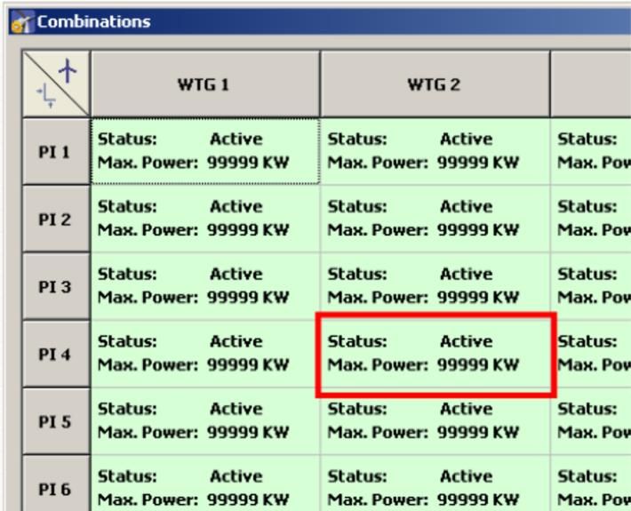
Revision history

Revision      Date         Change                                Author

1.0           01/03/2021   Translation of first German edition   IH
CONTENTS

1      ABOUT THIS MANUAL                                               4

2      INTRODUCTION                                                    6
2.1    Requirements for using Shadow Manager                            6
2.2    Preparing the communication with the SIM                         7
2.3    Preparing the shadow impact module                               8
2.4    Overview of menus and features                                   9
2.5    Overview of the configuration procedure                         12

3      THE CONFIGURATION WINDOWS                                       14
3.1    Project data window                                             14
3.2    Places of immission (IO) window                                 17
3.3    Wind turbine generators (WTG) window                            21
3.4    Combinations window                                             25
3.5    Overview map window                                             28
3.6    Data interface configuration window                             30
3.7    Switching conditions window                                     31
3.8    Time slice shutdown window                                      37
3.9    Shutdown calendar window                                        43
3.10   Module State window                                             46

4      THE COMMUNICATIONS WINDOWS                                      50
4.1    SIM connection window                                           50
4.2    IP address list window                                          51
4.3    Communication window                                            53
4.4    Light sensor window                                             55
4.5    Walls and areas window                                          57
4.6    Module State window                                             58

5      TYPICAL CONFIGURATION EXAMPLES                                  59
5.1    Set up a new WTG with a new PI                                  59
5.2    Checking whether PIs and WTGs have been defined correctly       61
5.3    Configure changed allowable shadow impact periods for the PIs   63
5.4    New bat protection requirements                                 64
5.5    Editing the combination of PIs and WTGs                         67

6      TROUBLESHOOTING                                                 69
Shadow Manager 1 – Manual

1      About this manual
In this manual, you will find information on how to install Shadow Manager as well as detailed
instructions on how to configure your shadow impact module using this software.

Manual structure
This manual can be used in various ways:
Chapter 1
Here you will find notes on how to use this manual, and you can look up abbreviations
used throughout the manual.
Chapter 2
This chapter explains how to prepare a configuration session and outlines the menus and
features as well as the basic procedure of a configuration session.
Chapter 3
This chapter provides a detailed description of the configuration windows including all
parameters and buttons available: use this chapter to look up individual parameters or
features.
Chapter 4
This chapter provides a detailed description of the communication windows including all
parameters and buttons available: use this chapter to look up individual parameters or
features.
Chapter 5
This chapter illustrates typical configuration tasks and provides step-by-step instructions.
Chapter 6
Here you will find trouble shooting information for the rare cases when the software and/or
the shadow impact module show unexpected behaviour.

Abbreviations and terms
This manual uses the following abbreviations and terms:

Abbreviation             Meaning

PI                       place of immission

LS                       light sensor

SIM                      shadow impact module

WTG                      wind turbine generator

SIIU                     shadow impact interface unit

Rev. 03/2021, Modifications and errors excepted                                                  4
Shadow Manager 1 – Manual

Abbreviation             Meaning

CU                       central unit
                         The central unit comes installed in a switch cabinet. The CU is installed in
                         the tower base of a WTG. Depending on the tower type, the switch cabinet
                         can either be installed to the ground using a support foot or fastened
                         directly to the tower wall.
                         Functions of the CU:
                              • calculates shadow impact periods at buildings to be protected
                              • retrieves light sensor data
                              • communicates with wind turbine generators (WTG)
                              • stops the relevant WTG when the shadow impact limit has been
                                exceeded
                              • automatically shuts down WTGs according to specified time periods
                                and meteorological conditions (protection of bats)
                              • records all shadow impact and WTG shutdown events

Navigational aids
If you read this manual on-screen, numerous cross references (hyperlinks) are available to
quickly navigate to a related paragraph providing further information. Hyperlinks are indicated
with a red arrow .

Trademark notice
Windows, Microsoft and Excel are either trademarks or registered trademarks of the
Microsoft Corporation in the United States or other countries.

Copyright and warranty
Copyright © 2021 NorthTec GmbH & Co. KG
All rights reserved.
We have prepared this manual with due care and checked it carefully. However, we cannot
guarantee that it is free of errors.
Furthermore, NorthTec GmbH & Co. KG reserve the right to make changes to this manual or
the products described herein at any time without notice. Furthermore, NorthTec GmbH &
Co. KG will not be liable for any loss, damage or consequential damage resulting from the
use of this manual or from the improper use of the products described in it.

Rev. 03/2021, Modifications and errors excepted                                                         5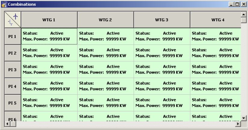
Shadow Manager 1 – Manual

2     Introduction
Thank you for purchasing our Shadow Manager software.

Purpose of the software
Software for the configuration of shadow impact modules according to project-specific
requirements.
Apart from the project data of the WTGs, you also have to define walls and areas of affected
places of immission (PI) and often additional parameters.

                  Please be very careful when entering values in Shadow Manager.
                  Incorrect parameter values may result in unnecessary wear and tear,
                  loss of earnings, problems with authorities/residents and in the worst
                  case force operators to decommission wind turbine generators. If in
                  doubt, call us in order to avoid making mistakes.

2.1 Requirements for using Shadow Manager
In order to use Shadow Manager for the configuration of your shadow impact module (SIM)
on a computer, the following technical requirements must be met:
SIM                         SWM V 3.5

Computer                    OS Microsoft© Windows XP© or later
                            64 MB RAM minimum
                            30 MB free hard disk memory minimum

Connection                  The data must be read out using a network connection (TCP/IP), see
                                2.3 Preparing the shadow impact module on page 8.

Shadow Manager              You can download the latest version of Shadow Manager from our
                            homepage (www.northtec.de). Each time you start Shadow Manager,
                            the software automatically checks if a new software version is available.
                            If there is, it downloads and installs the latest version. In the Help menu
                            you can search for updates manually at any time.

Product key                 In order to configure an SIM using Shadow Manager, you have to
                            purchase a product key from us. If you want to use Shadow Manager to
                            configure several SIMs, you need a separate product key for each SIM
                            (or for each project in Shadow Manager). We usually send the product
                            key via email, and you save it to your computer.

Rev. 03/2021, Modifications and errors excepted                                                       6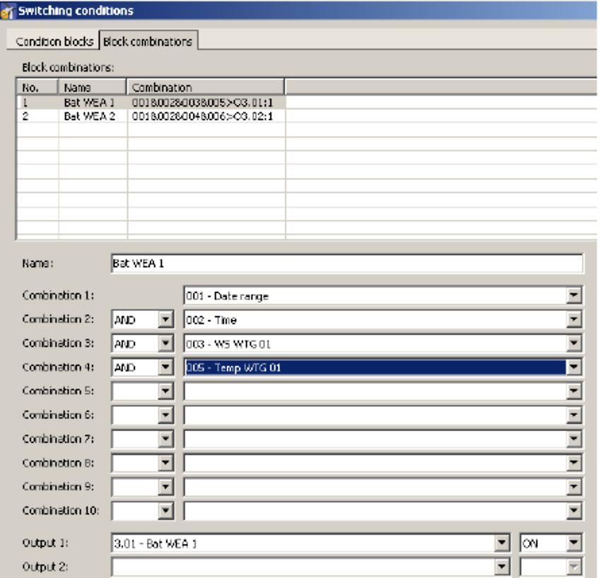
Shadow Manager 1 – Manual

2.2 Preparing the communication with the SIM

Before you can use Shadow Manager to configure shadow impact modules, you have to
carry out the following steps:

         Install Shadow Manager

Double-click on the installation file Setup Shadow Manager you have received via email or
downloaded from our server and follow the instructions on the screen.
After a few seconds, the installation procedure will be completed and Shadow Manager is
ready for use.

         Set up Ethernet/LAN communication in Windows

You will find the IP settings of the shadow impact module on the label attached to the
inside of the cabinet door. If there is no label, the SIM uses the default settings (IP address
192.168.002.060, subnet mask 255.255.255.000).
If you want to connect your computer directly to the shadow impact module using a network
cable, check the TCP/IP settings (Windows Vista© or later versions: TCP/IPv4) of your
computer: the first three sets of digits of the IP address have to be the same as the first three
sets of digits of the SIM IP address whereas the last set of digits (060 in the example above)
must not be identical.
For information on changing the settings, please refer to the Windows© help (search for
TCP/IP settings or respectively TCP/IPv4 settings).

Note: If you are not sure whether the IP information on the inside of SIM cabinet door is still
up-to-date, you can also check this information directly on the SIM. To do this, open menu
2.8.2 on the SIM display.

         Set up Shadow Manager

Double-click the Shadow Manager icon on your desktop to start the software.
Select Configuration > Language to change the display language to English.
   1. To load a product key, open the Licenses window from the Help menu and click on
      Add license.
   2. Now select the valid product key from the folder to which you saved the license key
      received from us via email. Then click on Open, and the selected product key will be
      added to the list shown in the Licenses window. Close the Licenses window.
   3. Select Configuration > SIM connection.
   4. Enter the data for communication with the SIM. Click on OK.
For more information on the SIM connection window, see          4.1 SIM connection window.
The software is now ready to communicate with the SIM.

Rev. 03/2021, Modifications and errors excepted                                                     7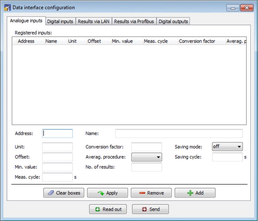
Shadow Manager 1 – Manual

2.3 Preparing the shadow impact module

In order to transmit the configuration data from the software to the SIM and vice versa, you
must set up a network connection between the computer and the SIM. There are two ways to
do this:
   • direct connection between computer and SIM via crossed Ethernet cable
   • connection via router and VPN connection

Note: If the SIM is connected to the network of a wind park, you have to adjust the TCP/IP
settings of the SIM to the range of IP addresses of the wind park network. The SIM cannot
obtain IP addresses from a router automatically.

         Set up the connection using an Ethernet cable

Use a crossed Ethernet cable to connect the Ethernet port of the SIM to the Ethernet port
of your computer.

                        Only qualified personnel is allowed to open the cabinet of the Shadow
                        Impact Module (SIM).
                        The high voltage present inside the SIM cabinet may cause serious
                        injury or even death!

         You can test the LAN connection using the PING command in
         Windows.

Rev. 03/2021, Modifications and errors excepted                                                 8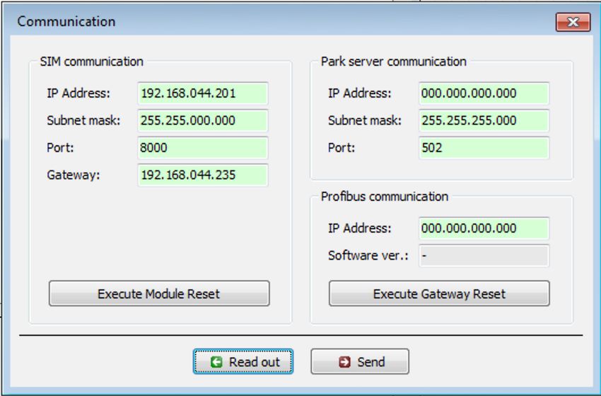
Shadow Manager 1 – Manual

2.4 Overview of menus and features

The menus File, View, Configuration and Help are available in the upper left of the Shadow
Manager main window.
The following tables provide an overview of the individual configuration and information
windows available in the menus.
Many windows can be opened directly by clicking on the respective icon in the main window.
The menus can be opened using shortcuts. Just press Alt + first letter of the menu name
(e. g. Alt + F to open the File menu).

File menu
When using the functions of the File menu, please follow the instructions on the screen.

 Icon       Window                    Description
            New project               Create a new project.

            Open project              Open an existing project.

            Save project              Save a project.

            Print                     Print a project – you can export the project data as PDF or
                                      print it on paper. Before printing, you can select the language
                                      from German or English and then decide whether you want to
                                      print all data or only selected parts by checking or unchecking
                                      the respective boxes.

            Export                    Export the project to Google Earth – so far, this feature is
                                      available only if the Gauss-Krüger coordinate system is used.
                                      For further information, please contact NorthTec GmbH
                                      directly.

            Send configuration        Send the configuration data of a project to an SIM: after you
                                      have created or edited a project, you must send the project
                                      data to the SIM. Otherwise the data will not be applied.

            Read out                  Read out a project’s configuration data: if you want to edit or
            configuration             complement data already in use by the SIM, you first have to
                                      read out the data from the SIM.

            End                       Exit Shadow Manager.

Rev. 03/2021, Modifications and errors excepted                                                         9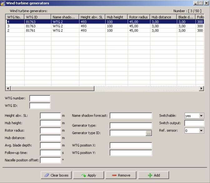
Shadow Manager 1 – Manual

View menu
The following table provides an overview of the View menu.
For a detailed description of the individual configuration windows, please refer to
   3 The configuration windows.

Icon       Window                    Description

           Project data              Edit and view project-specific information on site,
                                     commissioning, customer etc., see section       3.1.

           Places of immission       Edit and view the areas/wall possibly affected by shadow
                                     impact, see section    3.2.

           Wind turbine              Edit and view the data of a WTG whose shadow impact is to be
           generators                determined, see section     3.3.

           Combinations              This is where WTGs can be combined with places of immission
                                     (PI), see section 3.4.

           Overview map              Verify the position of WTGs and PIs, see section       3.5.

           Data interface            Define various analogue and digital input signals, see section
           configuration               3.6.

           Switching conditions      Define shutdown conditions – used for example to meet official
                                     requirements regarding bat protection, see section 3.7.

           Time slice shutdown       Used for bat protection: devide the night into time periods and
                                     define individual shutdown conditions for each period, see
                                     section     3.8.

           Shutdown calendar         Calendar for scheduling fixed shutdown times, see section
                                       3.9.

           Module state              Read out real-time data from the SIM and test stop and start
                                     commands for WTGs, see section       3.10.

Rev. 03/2021, Modifications and errors excepted                                                        10
Shadow Manager 1 – Manual
Configuration menu
Icon Window Description
SIM connection Used to set up a connection to the SIM. For further information
on this window, please refer to 2.2 Preparing the
communication with the SIM.
Communication This window is used only if the wind turbine generators to be
monitored are part of a wind park and if there is a park server.
For further information on this window, please refer to
4.3 Communication window.
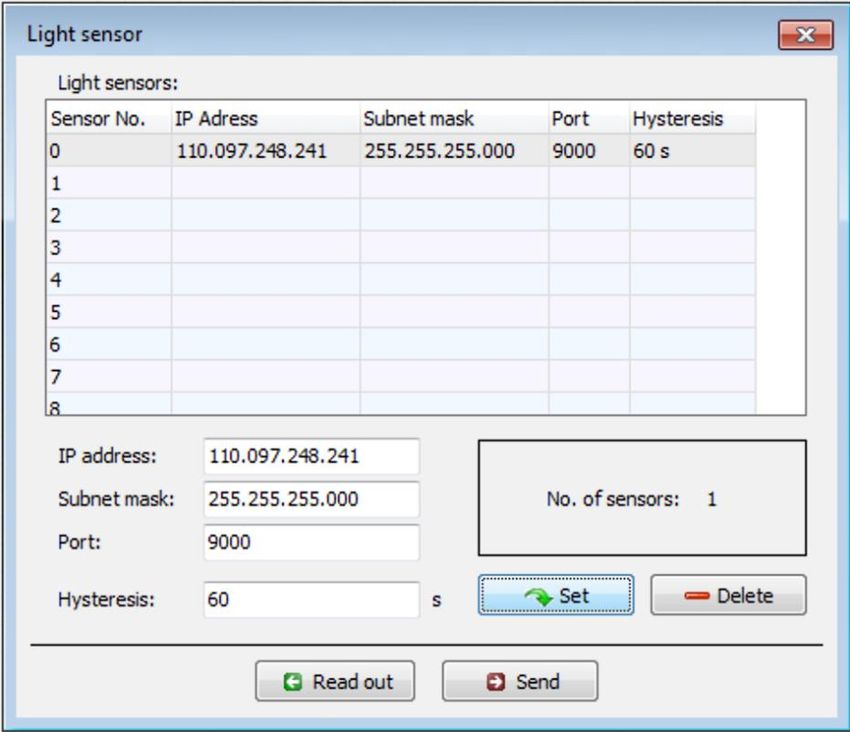
Light sensor This window can be used to configure, read in or read out the
data for setting up a connection to a light sensor. Up to 20 light
sensors can be configured. For further information on this
window, please refer to 4.4 Light sensor window.
Walls and areas In this window, you may limit the length of walls and area sides.
By configuring this parameter you can avoid defining a wall or
areas that are much larger than the actual wall/area. Defining
walls/areas that are too large can result in unnecessary
shutdowns of WTGs.
For further information on this window, please refer to
4.5 Walls and areas window.
Module state Set the cycle at which the data in the two tabs of the
Module State window are queried.
For further information on this window, please refer to
4.6 Module State window.
Language Here you can select a language: either German or English.
Help menu
Icon Window Description
NorthTec homepage Open the NorthTec homepage.
Licenses Add und remove von licenses.
Check for updates If you select this menu item, the software will carry out an
online check for updates of Shadow Manager.
About Shadow Displays information on the software version, information on
Manager NorthTec (phone number, address etc.) as well as information
on the operating system used.
Rev. 03/2021, Modifications and errors excepted 11Shadow Manager 1 – Manual
2.5 Overview of the configuration procedure
After you have carried out all preliminary steps on the computer, in the software and on the
SIM, you can start the actual configuration procedure.
Create or open a project
• To create a new project, click on (in the File menu or in the icon bar).
OR
• To open an existing project, click on (Open project in the File menu or in the
icon bar) and select a configuration file (format: .swk).
Load a product key
In both cases, you may have to select a product key belonging to the project from a drop-
down list.
If you want to use Shadow Manager to configure several SIMs, you need a separate product
key for each SIM (or for each project in Shadow Manager). For information on how to load a
product key, please refer to 2.4
Rev. 03/2021, Modifications and errors excepted 12Shadow Manager 1 – Manual
Overview of menus and features.
Read out the data from the SIM
If you are not sure whether the data contained in an existing project file (.swk) match the data
saved in the SIM, read out the data from the SIM (choose File > Read out configuration) to
be on the safe side.
Even if you have created a new project and you have not yet configured any data in the SIM,
we recommend you read out the data from the SIM. This saves you from having to configure
the data in the windows Communication and Light sensor from scratch.
Edit the configuration windows
After you have created or opened a project you can edit, check or change the configuration
data in the individual configuration windows as desired.
For detailed information on the configuration options in the individual windows, please refer
to the respective sections in Chapter 3 The configuration windows.
Please note that due to technical reasons, Shadow Manager uses
decimal commas instead of decimal points.
Preparing the communication with the light sensor
To enable the SIM to communicate with the light sensor, you have to configure the
parameters under Configuration > Light sensor.
For further information, please refer to 4.4
Rev. 03/2021, Modifications and errors excepted 13Shadow Manager 1 – Manual
Light sensor window.
Preparing the communication with the park server
If the SIM is connected to the network of a wind park, you have to enter the TCP/IP settings
of the wind park server under Configuration > Communication. Ask the WTG manufacturer
for the required data (IP address, subnet mask, standard gateway).
For further information, please refer to 4.3 Communication window.
Send configuration to the SIM
To apply the settings configured within Shadow Manager, you have to send the data to the
SIM.
To send a configuration to the SIM, click on or choose File > Send configuration. Then
enter the 4-digit SIM password in the Password prompt window. If a password has not been
set, enter the default password 0000.
Now Shadow Manager will send your configuration data to the SIM. You will receive a
transmission protocol showing the data transmitted to the SIM.
Please be very careful when entering values in Shadow Manager.
Incorrect parameter values may result in unnecessary wear and tear,
loss of earnings, problems with authorities/residents and in the worst
case force operators to decommission wind turbine generators. If in
doubt, call us in order to avoid making mistakes.
Rev. 03/2021, Modifications and errors excepted 14Shadow Manager 1 – Manual
3 The configuration windows
To configure the SIM using Shadow Manager you edit parameters within configuration
windows. The configuration windows can be opened either from the View menu or by clicking
the respective button in the icon bar. On the following pages, you will find a detailed
description of the individual configuration windows.
Please note that due to technical reasons, Shadow Manager uses
decimal commas instead of decimal points.
3.1 Project data window
To open this window, click on or choose View > Project data.
This window is used to edit and display project-specific information, such as site,
commissioning, customer etc.
general information
details on site,
scope, etc.
contact information
Fig.: Project data window
Rev. 03/2021, Modifications and errors excepted 15Shadow Manager 1 – Manual
The Project data window offers the following information and setting options.
Project data window
Project name Enter any characters.
Site Enter any characters.
AC Area code, enter any characters.
Country, state: Enter any characters.
Module number This number is read out from the SIM and cannot be
changed manually.
Module location The function of the Module location item is relevant
only for generator type 108. For all other generator
types, this parameter is only for information.
The shadow impact interface units (SIIU) used for
generator type 108 have a digital output which is
connected to the respective control of the WTG in order
to transmit alarm messages. This way, the SIIUs can
actively signal an alarm. In addition, the WTG control is
enabled to detect a failed SIIU since under normal
conditions, the operating status of the SIIU is "active".
In addition, the central unit (CU) can also output an
alarm message via the SIIU, e. g. when a light sensor
has failed. This only works, if the SIIU used is installed
in the same WTG as the central unit itself. To enable
the central unit to identify this SIIU, you must configure
the module location according to the ID number of the
WTG in which the central unit is installed. ID number
refers to the number indicated on the outside of the
tower. The central unit will find this ID number in the
settings of the WTG and can allocate the associated
SIIU.
Longitude It is possible to enter this information in Shadow
Manager. However, in order to ensure accuracy, you
should read out the data from the light sensor.
Inaccurate data may result in major calculation
inaccuracies.
Latitude as above
Coordinates format Read only: The coordinate’s format refers to the PI and
WTG.
No. of plcs. of immission Number of places of immission configured within this
project.
Number of monitored WTGs Number of WTGs monitored by the SIM.
Number of pre-loaded WTGs Here you can enter the number of pre-loaded WTGs.
Number of WTGs with special This field indicates the number of WTGs for which it is
shutdowns possible to set up a "special shut down".
Rev. 03/2021, Modifications and errors excepted 16Shadow Manager 1 – Manual
Project data window
Commissioning Here you can enter the date on which the SIM was
commissioned.
Data sources Here you can enter a range of different information for
individual purposes or for the authorities.
Name of client Enter any text.
Client address Enter any text.
Contact Enter any text.
Phone Enter any number.
Mobile Enter any number.
Email johndoe@dummy.xx
Operator Enter any text.
Service tel. No. Here you can enter e.g. the phone number of the
operator or the hotline number of the manufacturer.
Click this button if instead of reading out the entire
project from the SIM you want to read out only the
Project data.
Click this button if instead of sending the entire project
to the SIM you want to send only the Project data.
Please be very careful when entering values in Shadow Manager.
Incorrect parameter values may result in unnecessary wear and tear,
loss of earnings, problems with authorities/residents and in the worst
case force operators to decommission wind turbine generators. If in
doubt, call us in order to avoid making mistakes.
Rev. 03/2021, Modifications and errors excepted 17Shadow Manager 1 – Manual
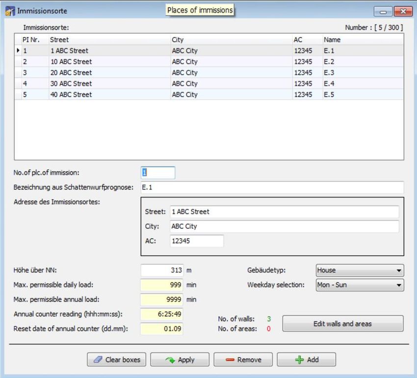
3.2 Places of immission (IO) window
To open this window, click on or choose View > Places of immission.
This window is used to edit and display project-specific information, such as site,
commissioning, customer etc.
list of PIs
(display area)
data of the PI
selected above
(input area)
buttons
Fig.: Places of immission (IO) window
The upper part of the screen lists the PIs already created. The information "14/300" in the
upper-right corner of the screen means that 14 of 300 possible PIs have been created so far.
The lower part of the screen is used to create or edit PIs. In addition, there are 6 buttons
available.
The Places of immission window offers the following information and setting options.
Places of immission window
No.of plc.of immission Serial number of the PI. Up to 300 PIs can be configured.
Name from shadow impact Name of the PI as used in a shadow impact forecast which
forecast may have been created.
Address of pl. of immission Exact address of the PI (street name, city, area code)
Height abv. SL Height above sea level in meters
Rev. 03/2021, Modifications and errors excepted 18Shadow Manager 1 – Manual
Places of immission window
Max. permissible daily load Maximum daily load in minutes as specified by the
authorities.
Max. permissible annual load Maximum annual load in minutes as specified by the
authorities.
Annual counter reading This is the total period over which the selected PI has been
(hh:mm:ss) loaded with shadow impact over the present year under
consideration.
IMPORTANT: We strongly recommend you read out the
annual counter before you make changes. Otherwise the
preload used after sending the project file to the SIM may be
incorrect.
Reset date of annual counter As the "shadow impact year" is not necessarily the same as
(dd:mm) the calendar year, you can set a different date here.
Note: When exchanging the hardware (SIM), proceed as
follows: first read out this value from the SIM to Shadow
Manager; after the new SIM has been installed, read out the
value from Shadow Manager to the SIM.
Building type Drop-down list offering the following selection: House,
Commercial, Stable, Church or Open area.
Weekday selection Drop-down list offering the following selection: Mon-Sun,
Mon-Sat, Mon-Fri, Sat+Sun
Example: For a commercially used building for example, you
may choose Mon-Fri, for a house used as a weekend
cottage, you may choose Sat+Sun.
No. of walls This field indicates only the number of walls. For creating or
editing a wall you use the Edit walls and areas window.
No. of areas as above
Please refer to "Edit walls and areas" below.
Deletes the data you entered in the free text field of the
selected PI.
Applies the entered data.
Attention: If you close this window before you have clicked
this button, all entries/changes you may have made will be
discarded.
Deletes the PI selected in the list. Attention: If you click this
button, the PI will be deleted immediately. There is no
confirmation prompt.
Used to add a new PI number. Up to 300 PIs can be
configured.
Rev. 03/2021, Modifications and errors excepted 19Shadow Manager 1 – Manual
Edit walls and areas window
To open this window, select a PI from the list of PIs in the Places of immission window and
then click on Edit walls and areas.
In the Edit walls and areas window, you can edit or create walls and areas for an existing
PI.
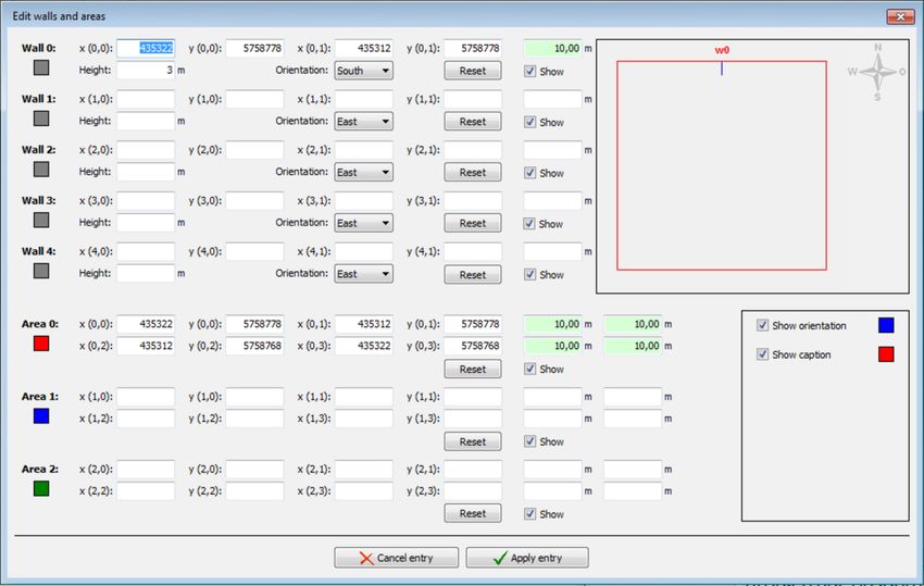
Fig.: Edit walls and areas window (section)
Example of a defined wall
• Wall 0 in the example above is defined by Gauss-Krüger coordinates [(x 0.0)/(y 0.0)
and (x 0.1)/(y 0.1)] and by Height in meters (3 m in this case).
• The value shaded in green is the result of the defined coordinates and indicates that
the length of the wall is 10 m.
• Since the Show box for this wall and the Show orientation box (right edge of screen)
are checked, wall 0 (w0) is indicated in the upper right corner by a blue line.
• Since the orientation of the wall was set to South, the blue line is below the wall
(southern orientation).
Example of a defined area
• Area 0 in the example above is defined by Gauss-Krüger coordinates [(x 0.0)/(y 0.0),
(x 0.1)/(y 0.1)], (x 0.2)/(y 0.2) and (x 0.3)/(y 0.3)].
• The values shaded in green on the right are the result of the defined coordinates. They
indicate that each of the four sides of the area is 10 m long.
• Because the Show box is selected, the area shows in the upper right as a red square.
Rev. 03/2021, Modifications and errors excepted 20Shadow Manager 1 – Manual
Important notes for defining walls and areas
• The points defining area must be entered clockwise: by no means should they be
entered in a criss-cross manner.
• The blue line in the field displaying walls and areas in the upper-right of the screen
indicates the outside of a wall.
• If the parameter defining a wall or an area in meters (the field to the right of the
coordinates fields) is shaded in red (instead of green), then the entered values are
not plausible or the maximum length of a wall or side of an area has been
exceeded. Check whether you entered the coordinates correctly. The maximum
length of a wall or of the sides of an area is set in the Configuration menu under
Walls and areas. For further information, please refer to section 4.5.
• Walls and areas you have edited or created will only be saved and applied if you
click the Apply entry button.
• The coordinates of all WTGs and PIs must be defined using the same metric
coordinate system.
• The Reset button can be used to delete an entire area or wall with one click.
Please be very careful when entering values in Shadow Manager.
Incorrect parameter values may result in unnecessary wear and tear,
loss of earnings, problems with authorities/residents and in the worst
case force operators to decommission wind turbine generators. If in
doubt, call us in order to avoid making mistakes.
Rev. 03/2021, Modifications and errors excepted 21Shadow Manager 1 – Manual
3.3 Wind turbine generators (WTG) window
To open this window, click on or choose View > Wind turbine generators.
This window is used to edit and display each WTG.
list of WTGs
(display
area)
data of the
WTG
selected
above
(input area)
buttons
Fig.: Wind turbine generators window
The upper part of the screen lists the WTGs already created. The information "3/50" in the
upper-right corner of the screen means that 3 of 50 possible WTGs have been created so far.
The lower part of the screen is used to create or edit WTGs. In addition, there are
4 buttons available.
The Wind turbine generators window offers the following information and setting options.
Wind turbine generators window
WTG number Freely definable number of the wind turbine generator
WTG ID Unique ID number of the WTG as indicated on the outside of the tower.
This is a mandatory field. The number entered in this field is used as the
WTG name in the Shadow Impact Log.
Height abv. SL WTG’s height above sea level in meters
Hub height WTG’s hub height in meters
Rotor radius Rotor radius in meters
Rev. 03/2021, Modifications and errors excepted 22Shadow Manager 1 – Manual
Wind turbine generators window
Hub distance Distance between the hub and the centre of the tower in meters
Avg. blade depth This parameter will be used in the future.
Follow-up time The period of time in seconds during which a WTG after having been shut
down by the SIM will not be started up even if the sky is clouding over.
Nacelle position Difference between the nacelle position used by the park server and the
offset actual position (orientation) in degrees.
Name shadow Name of the WTG as used in a shadow impact forecast which may have
forecast been created (reference only).
Generator type If shadow impact interface units (SIIU) are deployed, this parameter is
used to obtain the right gear ratio for calculating the rotor speed. For this
reason, it is important to adhere to the following notation:
3.2M
3.4M
GE 2.5-100
MM82
MM92
If no SIIU is used, this is only for information.
Generator type ID This parameter defines the way in which the shadow impact system can
communicate with the WTG. The following is defined: method for
transmitting start and stop commands to the WTG and the types of WTG
operating data available for the shadow impact system.
Some generator types do not transmit any operating data to the WTG. In
this case the periods of shadow impact are calculated based on two
assumptions: the rotor is always in a rectangular position to the direction
of the sun’s rays and the WTG is in permanent operation. The shadow
impact periods determined by this method exceed the actual periods of
shadow impact by 20-30 %.
It is not possible to enter an ID that has not been pre-defined in the
selection menu.
The IDs 100, 101, 104, 106, 107, 109, 110, 111 as well as 113 through
118 are manufacturer-specific and serve special interfaces.
The manufacturer-independent IDs have the following meaning:
102
The stop and start commands for the WTG are transmitted from the
central unit (CU) to a light sensor. The light sensor (0-19) is selected
under Switch output, see below.
For this procedure, the light sensor’s digital output must be connected to
the control unit of the WTG using a coupling relay. Once the light sensor
receives a stop command from the central unit, the digital output is
activated. As soon as the stop command is cancelled, the digital output is
reset. For this type of generator it is not possible to transmit WTG
operating data to the shadow impact system.
Rev. 03/2021, Modifications and errors excepted 23Shadow Manager 1 – Manual
Wind turbine generators window
103
This generator type is selected if the preload caused by a WTG must be
taken into account for the calculation. The shadow impact system can
neither stop this WTG nor retrieve its operating data.
105
For this generator type, the central unit provides a floating relay contact
(normally closed contact/normally open contact) for transmitting the stop
and start commands to the WTG. If the shadow impact system monitors
several WTGs of this type of, the digital signals have to be distributed via
an park-internal optical waveguide (fibre optic cable) network.
For this type of generator it is not possible to transmit WTG operating data
to the shadow impact system.
108
This generator type is selected if a shadow impact interface unit (SIIU) is
used to transmit the stop and start commands to the WTGs as well as to
transmit the WTG operating data to the shadow impact system. The SIIU
has 0-20 mA inputs for receiving data on nacelle position, current output,
WTG gear or rotor speed as well as wind speed. This information is
transmitted to the central unit using a network connection (TCP/IP) and
taken into account for the calculation of the shadow impact periods. The
start and stop commands are also transmitted using the network
connection.
112
This generator type is selected if a shadow impact interface unit (SIIU) is
used to transmit the stop and start commands to the WTGs. The start and
stop commands are transmitted using the network connection (TCP/IP).
For this type of generator it is not possible to transmit WTG operating data
to the shadow impact system.
WTG position X Coordinates of the WTG position.
WTG position Y NOTE: The coordinates of all WTGs and PIs must be defined using the
same metric coordinate system.
Switchable Drop-down list for selecting from: no, yes
NOTE: This parameter specifies whether it is possible for the SIM to
switch (yes) the WTG or not (no).
Switch output This parameter is relevant only for WTG types 102, 105 and 106.
For WTG type 102 it specifies the light sensor to be used to switch the
WTG. For WTG types 105 and 106 it specifies the digital output of the SIM
to be used to switch the WTG.
Ref. sensor Number of the light sensor whose measuring data are used by the SIM to
determine whether a given WTG caused shadow impact or not. Reference
sensors 0-19 can be defined. If this parameter is set to 99, then all light
sensors will be taken into account as reference sensors.
Deletes the data you entered in the free text field of the selected WTG.
Applies the entered data.
Attention: If you close this window before you have clicked this button, all
entries/changes you may have made will be discarded.
Rev. 03/2021, Modifications and errors excepted 24Shadow Manager 1 – Manual
Wind turbine generators window
Deletes the WTG selected in the list. Attention: If you click this button,
the WTG will be deleted immediately. There is no confirmation prompt.
Used to add a new WTG No. Up to 50 WTGs can be configured.
Important note on defining WTGs
• The coordinates used to define WTGs and PIs must be based on the same metric
coordinate system.
Please be very careful when entering values in Shadow Manager.
Incorrect parameter values may result in unnecessary wear and tear,
loss of earnings, problems with authorities/residents and in the worst
case force operators to decommission wind turbine generators. If in
doubt, call us in order to avoid making mistakes.
Rev. 03/2021, Modifications and errors excepted 25Shadow Manager 1 – Manual 3.4 Combinations window To open this window, click on or choose View > Combinations. To ensure that the shadow impact caused by a WTG will be related to a PI, the WTG and the PI must be combined with each other. In the Combinations window, you can enable or disable any combination of any configured PI with any configured WTG. You can also specify a maximum power in KW for the respective combination. Upon configuration of WTGs and PIs, all combinations are set to Active by default. As a result, the SIM will assume that each WTG is able to cause shadow impact in each PI. However, if there is an obstacle between a WTG and a PI, the occurrence of real shadow impact is not possible in this place of immission. Nevertheless, the SIM will detect theoretical shadow impact. In order to avoid this, the corresponding combination should be deactivated. Fig.: Combinations window Rev. 03/2021, Modifications and errors excepted 26
Shadow Manager 1 – Manual

The Combinations window offers the following information and setting options.

 Combinations window
                  Edit all combinations at the same time
                  If you click into the upper-left corner, the following window will be displayed:

                  The two checkboxes on the left are used to define whether the parameter on the
                  right should be changed or not.
                  The checkbox to the right of Active is used to enable or disable combinations.
                  The input field to the right of Power is used to define a power output limit in KW. If
                  the power output of a WTG falls below this limit, the WTG will be shut down when it
                  causes shadow impact even though the time limit at the PI may not have been
                  exceeded yet. This way, you can avoid that a WTG currently producing low power
                  output "eats up" the daily or yearly budget unnecessarily. If you don’t want the
                  power output to be monitored, enter 99999 (default).
                  In order to activate all combinations at once for example, make sure the checkbox
                  to the left of Active is selected, and then select the checkbox to the right of Active.
                  In order to specify a power output limit for all combinations in one step, make sure
                  the checkbox to the left of Power is selected and then enter the desired KW value
                  on the right.

                  Edit all combinations with one PI at the same time
                  Click into a PI field (PI 1 to N) in the far-left column to open the following window:

                  The parameters in this window are configured in the same ways as the ones in the
                  Set all combinations window above, except they apply only to the selected PI.

Rev. 03/2021, Modifications and errors excepted                                                             27
Shadow Manager 1 – Manual
Combinations window
Edit all combinations with one WTG at the same time
Click into a WTG field (WTG 1 to N) in the uppermost line to open the following
window:
The parameters in this window are configured in the same way as the ones in the
Set all combinations window above, except they apply only to the selected WTG.
Edit a single combination (combination of one PI with one WTG)
If you click on one of the fields shaded in green (or red), the following window will be
displayed:
Enable or disable the combination using the Active checkbox, and specify a power
output limit (KW) in the Power field if so desired.
Rev. 03/2021, Modifications and errors excepted 28Shadow Manager 1 – Manual
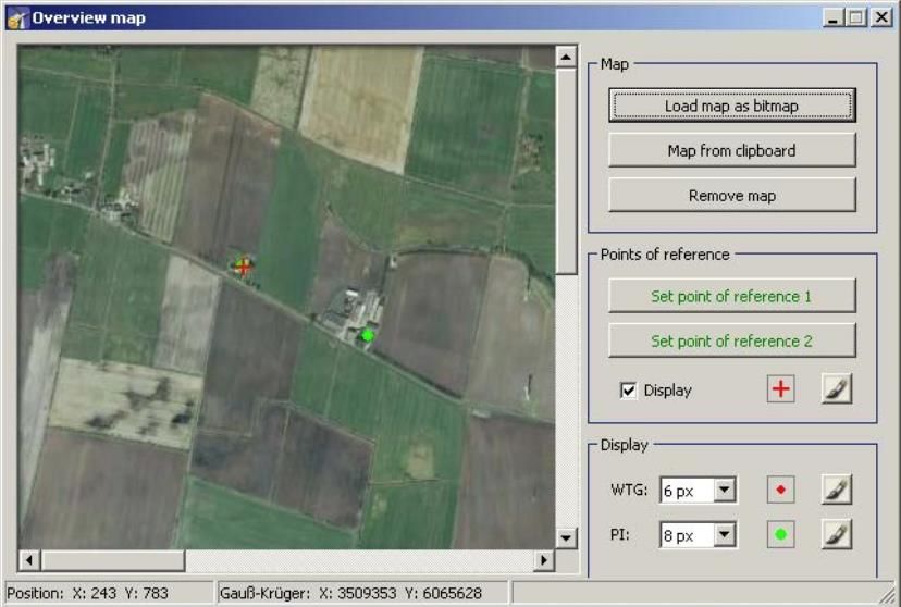
3.5 Overview map window
To open this window, click on or choose View > Overview map.
In the Overview map window, you can import a map in order to visually check that you have
defined the WTGs and PIs correctly.
The left part of the window displays the WTGs and PIs you have defined in the respective
configuration windows as well as the map (if you have imported one). In the right part of the
window, you can load and remove a map (bitmap), define reference points and change the
display settings for the WTGs and PIs.
Loading a background map and setting reference points works only if the
Gauss-Krüger coordinate system is used.
The Overview map window offers the following options.
Overview map window
Click this button to load a map to be displayed in the left part of the
window.
The format of the map must be bitmap.
Click this button to paste a map from the clipboard.
The format of the map must be bitmap.
Rev. 03/2021, Modifications and errors excepted 29Shadow Manager 1 – Manual
Overview map window
Click this button to remove the map.
After a background map has been loaded, you must define points of
reference within the map. Otherwise the WTGs and PIs may not be
displayed in the correct place.
To optimise the accuracy, the reference points should be as far apart
from each other as possible.
The reference points must be defined according to the Gauss-Krüger
format.
Click on Set point of reference 1 to set the first reference point. The
button will flash. Move the mouse pointer to the desired place in the map
and click.
For more information, see next line.
A window will open in which you have to enter the Gauss-Krüger
coordinates of the reference point. After you have entered the
coordinates, click on Set. The entered coordinates are applied and the
button name colour of Set point of reference 1 switches from red to
green. Repeat the above steps for second reference point.
In the Display area on the right you can change the pixel size of the
WTGs and PIs by clicking on the respective drop-down list to select a
different value.
To change the colours, click on the brush buttons on the right.
Position The current position of the mouse pointer is displayed at the lower edge
of the window.
Gauss-Krüger The current position of the mouse pointer is displayed at the lower edge
of the window in Gauss-Krüger coordinates.
Rev. 03/2021, Modifications and errors excepted 30Shadow Manager 1 – Manual
3.6 Data interface configuration window
To open this window, click on or choose View > Data interface configuration.
The Data interface configuration window is used to define various analogue and digital
signals.
list of
inputs/signals
(display area)
data of the
inputs/signals
selected above
(input area)
buttons
This section of the manual is in progress. For details on configuring data interface, please
contact NorthTec for now.
Rev. 03/2021, Modifications and errors excepted 31Shadow Manager 1 – Manual 3.7 Switching conditions window To open this window, click on or choose View > Switching conditions. The Switching conditions window is used to define conditions other than shadow impact as criteria for shutting down a WTG. Here you can for instance define the criterion of “wind speed” in order to comply with bat protection requirements. The creation of switching conditions involves two steps: • Creating condition blocks, e.g. date range, time, wind speed • Combining created condition blocks with each other using AND or OR Accordingly, the Switching conditions window comprises two tabs: Condition blocks and Block combinations. On the next page, the Condition blocks tab is described first, followed by the Block combinations tab. Rev. 03/2021, Modifications and errors excepted 32
Shadow Manager 1 – Manual

“Switching conditions” window, “Conditions blocks” tab

Fig.: Switching conditions window, Condition blocks tab

Notes on the above tab
  •   In the upper half of the screen of the Condition blocks tab, blocks that have already
      been created are displayed in list form; editing is not possible here.
  •   In the lower half of the screen you can edit the block selected above or add a new
      block.

A more detailed explanation of the input fields and buttons can be found in the table on the
next page.

Rev. 03/2021, Modifications and errors excepted                                                33
Shadow Manager 1 – Manual
The following input fields and buttons are available in the lower half of the Condition blocks
tab of the Switching conditions window.
Switching conditions window, Condition blocks tab
Name Use the left-hand white field to enter a name (free text) for the condition
block. Special characters cannot be entered. The right-hand white field
displays a serial number that is generated automatically.
Condition # This line offers the following input and selection options (from left to right):
Select one of the following interfaces from the first drop-down list: module
internal, digital input, analogue input, result LAN , result via Profibus.
If you have selected module internal, the next drop-down list will offer the
following criteria: Date, Time, Sunrise, Sunset, Elevation angle,
Azimuth.
If you have selected module internal, choose an operator to be applied to
the condition from drop-down list at the far right: = equal to, > greater than,
< less than, unequal to, >= greater than or equal to,Shadow Manager 1 – Manual
Response delay To ensure that the WTGs are not switched too frequently (high wear and
tear) when conditions relating to wind speed or temperature are involved,
you can specify here that the shutdown conditions need to be met
continuously over a specific period of time before a WTG will actually be
shut down.
Example: If 1800 seconds is entered here, then the respective WTG is
shut down only after the wind speed measured has been below the
defined limit value of, for example, 6 m/s continuously for half an hour.
Input: 0 to 3600 seconds
Release delay To ensure that the WTGs are not switched too frequently (high wear and
tear) when conditions relating to wind speed, precipitation or temperature
are involved, you can specify here that the shutdown conditions must
NOT be present for a specific period of time before a WTG is actually
started up again after having been shut down due to a special shutdown.
Example: If 1800 seconds is entered here, then the respective WTG, after
having been shut down due to a special shutdown, is started up again only
after a wind speed of, for example, 6 m/s or more has been measured
continuously for half an hour.
Input: 0 to 3600 seconds
Deletes the values selected/entered in the lower part of the screen.
Applies the entered/selected values. Attention: If you close this window
before you have clicked this button, all entries/changes you may have
made will be discarded.
Deletes the condition block selected in the list. Attention: If you click this
button, the condition block will be deleted immediately. There is no
confirmation prompt.
Adds a new condition block. Up to 100 condition blocks can be configured.
Reads out the switching condition from an SIM.
Sends the switching conditions to an SIM.
Rev. 03/2021, Modifications and errors excepted 35Shadow Manager 1 – Manual
list of block
combinations
(display area)
data of the block
combination
selected above
(input area)
buttons
Fig.: Switching conditions window, Block combinations tab
The upper part of the Block combinations tab lists the block combinations already created.
The lower part of the screen is used to create or edit block combinations. In addition, there
are 6 buttons available.
The Block combinations tab of the Switching conditions window offers the following
information and setting options.
Switching conditions window, Block combinations tab
Name Here you can enter a name (free text) for the block
combination; special characters are allowed.
Combination 1 Here you select one of the condition blocks you have
configured in the Condition blocks tab from the drop-down
list.
Combination 2 to N Select And or Or from the drop-down list on the left-hand
side.
Select one of the condition block configured before from the
drop-down list on the right-hand side.
Rev. 03/2021, Modifications and errors excepted 36Shadow Manager 1 – Manual
Switching conditions window, Block combinations tab
Output 1 to 3: The shadow impact module recognises three types of digital
outputs:
X=1
Actuates the digital outputs 1–12 of the display relay board.
The display relay board is an integral part of the central unit.
X=2
Actuates the digital outputs 1–30 of an optional output board.
X=3
This is selected to activate virtual outputs. Virtual outputs are
used if the wind turbine generator is to be actuated by way of
an interface (e. g. MODBUS/TCP). The second digit
designates the number of the WTG.
Deletes the values selected/entered in the lower part of the
screen.
Applies the entered/selected values. Attention: If you close
this window before you have clicked this button, all
entries/changes you may have made will be discarded.
Deletes the block combination selected in the list. Attention:
If you click this button, the block combination will be deleted
immediately. There is no confirmation prompt.
Adds a new block combination. Up to 50 block combinations
can be configured.
Reads out the switching condition from an SIM.
Sends the switching conditions to an SIM.
Please be very careful when entering values in Shadow Manager.
Incorrect parameter values may result in unnecessary wear and tear,
loss of earnings, problems with authorities/residents and in the worst
case force operators to decommission wind turbine generators. If in
doubt, call us in order to avoid making mistakes.
Rev. 03/2021, Modifications and errors excepted 37Shadow Manager 1 – Manual
3.8 Time slice shutdown window
Bat protection requirements can be so complex that different conditions apply in different
time periods of the night. To meet such requirements, SM1 offers the possibility of dividing
the night into time slices so that different shutdown conditions can be defined for each of
these time slices.
The time slices and their respective shutdowns are defined in the Time slice shutdown
window. To open this window, click on or choose View > Time slice shutdown.
The Time slice shutdown window includes the following two tabs:
• Time slices
This is where individual time slices and their respective limit values are configured.
• Assignments
This is where time slices defined in the Time slices tab are assigned to the project’s
WTGs.
On the next page, the Time slices tab is described first, followed by the Assignments tab.
Rev. 03/2021, Modifications and errors excepted 38Shadow Manager 1 – Manual
Time slice shutdown window, Time slices tab
Individual time slices and their respective limit values are configured in this tab.
Fig.: Time slice shutdown window, Time slices tab
Notes on the above tab
• In the upper area, the list of already defined date ranges is displayed on the left and
the list of time slices on the right – editing is not possible in the lists.
• Below the list of date ranges, you can change, remove or add ranges and also specify
the limit values that should be activated for the respective range.
• Below the list of time slices you can define the previously activated limit values.
A more detailed explanation of the input fields can be found in the table on the next page.
Rev. 03/2021, Modifications and errors excepted 39Shadow Manager 1 – Manual
The following input fields and buttons are available in the Time slices tab.
Time slice shutdown window, Time slices tab
Description Here you give a name to the date range you want to define.
Input: Enter any characters.
Start date Start date of the date ranges
Input: DD/MM (there is no period after the month)
(if Windows region setting = English)
End date End date of the date range
Input: DD/MM (there is no period after the month)
(if Windows region setting = English)
Start delay If you enter a value of e.g. 30 here, the time slice shutdowns will not
take effect until half an hour after sunset.
Input: 0 to 59 minutes
Early abort If you enter a value of, for example, 30 here, the time slice shutdowns
stop to take effect half an hour before sunrise.
Input: 0 to 59 minutes
Number of time slices Input: integer 1 to 20
Length of time slices The input defines the percentage of the total duration of the night (time
before sunset between sunset and sunrise). If you do not make an entry here, this time
slice will not be used.
Input: 0.00 to 50.00 percent
Length of time slices The input defines the percentage of the total duration of the night (time
after sunrise between sunset and sunrise). If you do not make an entry here, this time
slice will not be used.
Input: 0.00 to 50.00 percent
Activate limit values Here you can activate up to 4 limit values and in thus enable
• a "less than" condition for Wind speed
• a "less than" condition for Precipitation
• a "greater than" condition for Ambient temperature
• a "less than" condition for Humidity
The actual values are entered in the right half of the screen under
Limits.
Input: set/remove checkmark
Rev. 03/2021, Modifications and errors excepted 40Shadow Manager 1 – Manual
Time slice shutdown window, Time slices tab
Hysteresis You can also define a hysteresis for each limit value.
The hysteresis defines the desired permissible difference between the
switching points for start-up or respectively shutdown.
Example: Wind speed
To ensure that the WTG will not be switched too frequently during times
when the readings are unstable (e.g. gusty winds), you can delay the
response by specifying a hysteresis.
Only positive values can be entered. The direction in which the
hysteresis value works depends on whether the value refers to a "less
than" or "greater than" condition.
If a value of 6 m/s with a hysteresis of 1 m/s is set for wind speed, this
has the following effect:
The respective WTG is shut down if the wind speed falls below 6 m/s,
but is started up again only if a wind speed of more than 7 m/s is
measured.
Input: 0.00 to 10.00
Delayed condition To ensure that the WTGs are not switched too frequently (high wear and
complied with tear) when conditions relating to wind speed, precipitation or
temperature are involved, you can specify here that the shutdown
conditions need to be met continuously over a specific period of time
before a WTG will actually be shut down.
Example: Wind speed
If 30 seconds is entered here, then the respective WTG is shut down
only after the measured wind speed has been below the defined limit
value of, for example, 6 m/s continuously for half an hour.
Input: 0 to 60 minutes
Delayed condition not To ensure that the WTGs are not switched too frequently (high wear and
complied with tear) when conditions relating to wind speed, precipitation or
temperature are involved, you can specify here that the shutdown
conditions must NOT be present for a specific period of time before a
WTG is actually started up again after having been shut down due to a
special shutdown.
Example: Wind speed
If 30 minutes is entered here, then the respective WTG, after having
been shut down due to a special shutdown, is started up again only after
a wind speed of, for example, 6 m/s or more has been measured
continuously for half an hour.
Input: 0 to 60 minutes
Used to delete the entries made below the list of date ranges.
Used to confirm the entries made below the list of date ranges.
Attention: If you close this window before you have clicked this button,
all entries/changes you may have made will be discarded.
Deletes the date range selected in the list.
Attention: If you click this button, the date range will be deleted
immediately, there is no confirmation dialog.
Rev. 03/2021, Modifications and errors excepted 41Shadow Manager 1 – Manual
Time slice shutdown window, Time slices tab
Adds a new block combination. Up to 50 block combinations can be
configured.
Limits Here you define the limit values that were previously activated for the
respective period (left half of the screen). Limits that are not activated
are greyed out.
If you click this button for a limit value entered, the entry is applied to all
time slices.
Used to delete the entries made in the Limits area.
Used to confirm the entries made in the Limits area.
Attention: If you close this window before you have clicked this button,
all entries/changes you may have made will be discarded.
Rev. 03/2021, Modifications and errors excepted 42Shadow Manager 1 – Manual
Time slice shutdown window, Assignments tab
This is where time slices defined in the Time slices tab are assigned to the project’s WTGs.
Fig.: Time slice shutdown window, Assignments tab
Notes on the above tab
• The left half of the screen displays a list of the date ranges defined in the Time Slice
tab including all parameters.
• In the right half of the screen, you can activate or deactivate a currently selected date
range for each WTG of the project individually by checking or unchecking the
Assigned box.
• To easily manage large projects with many WTGs, the buttons Select all and Select
none are available at the bottom right.
Please be very careful when entering values in Shadow Manager.
Incorrect parameter values may result in unnecessary wear and tear,
loss of earnings, problems with authorities/residents and in the worst
case force operators to decommission wind turbine generators. If in
doubt, call us in order to avoid making mistakes.
Rev. 03/2021, Modifications and errors excepted 43Shadow Manager 1 – Manual
3.9 Shutdown calendar window
To open this window, click on or choose View > Shutdown calendar.
The Shutdown calendar window is used to define fixed shutdown times to be applied
without taking into account other conditions, such as position of the rotor with respect to the
direction of the sun’s rays. The only condition that can be configured in addition to time is
"sun is shining".
list of shutdown
periods
(display area)
data of the
shutdown period
selected above
(input area)
buttons
Fig.: Shutdown calendar window
The upper part of the screen lists the shutdown periods already created. The information
"2634/3500" in the upper-right corner of the screen means that 2634 of 3500 possible
shutdown periods have been created so far. However, the standard version of the SIM can
process no more than 2,500 shutdown periods.
The lower part of the screen is used to create or edit shutdown periods. In addition, there are
8 buttons available.
Rev. 03/2021, Modifications and errors excepted 44You can also read