Simulating an ultra broadband concept for Exawatt class lasers - Nature
←
→
Page content transcription
If your browser does not render page correctly, please read the page content below
www.nature.com/scientificreports
OPEN Simulating an ultra‑broadband
concept for Exawatt‑class lasers
Zhaoyang Li *
, Yoshiaki Kato & Junji Kawanaka
The rapid development of the optical-cycle-level ultra-fast laser technologies may break through the
bottleneck of the traditional ultra-intense laser [i.e., Petawatt (PW, 1015 W) laser currently] and enable
the generation of even higher peak-power/intensity lasers. Herein, we simulate an ultra-broadband
concept for the realization of an Exawatt-class (EW, 1018 W) high peak-power laser, where the wide-
angle non-collinear optical parametric chirped-pulse amplification (WNOPCPA) is combined with the
thin-plate post-compression. A frequency-chirped carrier-envelope-phase stable super-continuum
laser is amplified to high-energy in WNOPCPA by pumping with two pump-beamlets and injected
into the thin-plate post-compression to generate a sub-optical-cycle high-energy laser pulse. The
numerical simulation shows this hybrid concept significantly enhances the gain bandwidth in the high-
energy amplifier and the spectral broadening in the post-compression. By using this concept, a study
of a prototype design of a 0.5 EW system is presented, and several key challenges are also examined.
Since the invention of the chirped-pulse amplification (CPA), where optical nonlinearity and damage in ampli-
fiers are efficiently avoided, the peak-power of laser pulses has increased from Gigawatt (GW, 1 06 W) to PW
dramatically1. In the current PW lasers, the major laser amplification materials include Nd:glass, Ti:sapphire, and
nonlinear optical crystal. The Nd:glass has a very large physical size (> 1 m) but a very narrow gain bandwidth
(~ 20 nm FWHM), which has generated sub-picosecond, kilo-joule laser pulses with the current maximum
peak-power of 2 PW2. The Ti:sapphire crystal has a limited physical size (< 200 mm) but a broad gain bandwidth
(> 200 nm), which has generated 20–50 fs (limited by gain narrowing and gain saturation), < 400 J laser pulses
with the current maximum peak-power of 10 PW3,4. In the optical parametric chirped-pulse amplification
(OPCPA), for example the frequently used type-I Lithium triborate (LBO) crystal (pumped by 527 nm) also
has a > 200 nm gain bandwidth but a limited physical size (< 150 mm). However, since the optical parametric
amplification is free from the temporal-dependent gain saturation and gain narrowing, which can support < 20 fs
high-energy ultra-short laser pulses with the current maximum peak-power of 5 P W5, and the construction of
a 100 PW OPCPA laser facility has been started recently in S hanghai6,7.
As the next step to the EW-class laser, Fig. 1a shows two approaches that can be considered; one is to increase
the pulse energy, and the other is to reduce the pulse duration. The former approach is strongly dependent on
developing large-sized laser amplification materials (especially Ti:sapphire and nonlinear optical crystals) or
increasing the beamline number (facility scale). This approach has to face with technical, engineering, and eco-
nomic issues, for example parasitic lasing in a large-sized Ti:sapphire amplifier. Currently, the rapid development
of the optical-cycle-level ultra-fast laser technology makes the latter approach more and more attractive, and
may break through this bottleneck.
Coherent pulse synthesis, mainly demonstrated by F. Kärtner et al., enables the generation of an optical-cycle-
level, carrier-envelope-phase (CEP)-controlled light pulse by combining different-colored pulses from separate
sources/amplifiers8. Figure 1b schematically shows, by modulating phase, two light pulses from the sequential
(upper) or parallel (lower) scheme with different gain spectra are combined into a single ultra-broadband (ultra-
short) light pulse. Table 1 lists various experimental results9–17, where CEP-stable sub-optical-cycle (1.9 fs) light
pulses have been produced.
Post-compression (or named as re-compression, nonlinear compression, super-continuum generation, and so
on), demonstrated by M. Nisoli and F. Krausz et al., is a very important technology to generate optical-cycle-level
light pulses18–21. Figure 1c schematically shows that an ultra-short pulse is generated by broadening the spectrum
in a nonlinear device (e.g., gas-filled hollow-core fibers, crystal-photonics fibers, gas-filled cells, thin-plate bulk
materials, etc.) and compensating the induced temporal chirp with chirped mirrors. Table 1 also gives several
experimental results22–29, where CEP-stable sub-optical-cycle (1.2 fs) light pulses have been obtained25. Recently
the concept of post-compression, previously demonstrated with low-energy ultra-fast lasers, has been extended
to high-energy lasers by A. Zheltikov and G. Mourou et al. in order to generate few-cycle, PW and even EW
Institute of Laser Engineering, Osaka University, 2‑6 Yamadaoka, Suita, Osaka 565‑0871, Japan. *
email:
zhaoyang‑li@ile.osaka‑u.ac.jp
Scientific Reports | (2021) 11:151 | https://doi.org/10.1038/s41598-020-80435-6 1
Vol.:(0123456789)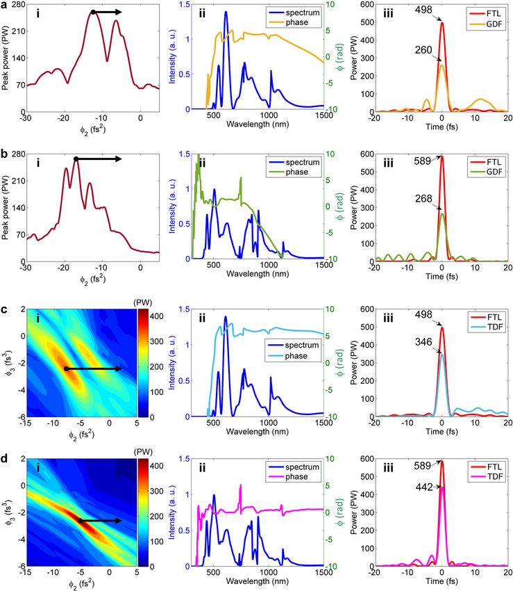
www.nature.com/scientificreports/
Figure 1. Approaches for peak-power/intensity scaling. (a) Two approaches of to increase pulse energy or to
reduce pulse duration for peak-power/intensity scaling. P, peak-power; I, peak intensity; E, pulse energy; t, pulse
duration; S, beam/focal-spot area. Ultra-fast optics methods to reduce pulse duration by broadening spectrum
of (b) coherent pulse synthesis with sequential (upper) or parallel (lower) scheme, (c) post-compression in
nonlinear medium [mainly by self-phase modulation (SPM)], (d) induced-phase modulation (IPM) with two
different input spectra, and (e) concept in this paper of combination of WNOPCPA and post-compression. The
inset in (d) schematically illustrates broader-band spectrum by IPM than that by SPM only.
Coherent pulse synthesis
Laser source (scheme) Spectrum Duration Peak-power References
9
EDFA (parallel) 0.9–1.4 & 1.6–2 μm 4.3 fs (1-cycle) 100 kW
10
EDFA + Ti:sapphire (parallel) 0.7–1 & 1–1.4 μm 3.7 fs (1.1-cycle) -
11
GF-HCF (parallel) 0.35–0.5 & 0.5–0.7 & 0.7–1.1 μm 2.1 fs (0.88-cycle) 0.15 TW
12
OPCPA (parallel) 0.75–1.05 & 1.9–2.5 μm 3.4 fs (0.8-cycle) 4.5 GW
13
OPA (parallel) 0.52–0.7 & 0.65–1 μm 3.8 fs (1.6-cycle) -
14
OPA (parallel) 0.5–0.75 & 0.65–1 & 1.2–2.3 μm 1.9 fs (0.4-cycle) -
15
TCP-OPA (sequential) 0.5–1 μm 4.6 fs (1.6-cycle) 0.2 GW
16
TCP-OPA (sequential) 0.6–0.7 & 0.7–1 μm 4.4 fs (1.6-cycle) 16 TW
17
TCP-OPA (sequential) 0.7–1.5 & 1.6–2.5 μm 3 fs (0.6-cycle) 8 GW
Post-compression
Nonlinear medium Spectrum Duration Peak-power References
22
GF-HCF 0.55–1 μm 4.3 fs (1.7-cycle) 0.2 TW
23
Ionizing gas 0.5–0.9 μm 3.8 fs (1.5-cycle) 0.3 TW
24
GF-HCF 0.5–1 μm 4 fs (1.6-cycle) 0.7 TW
25
GF-HCF 0.3–1 μm 1.2 fs (0.5-cycle) 0.2 TW
26
GF-HCF 0.5–1 μm 3.4 fs (1.5-cycle) 1 TW
27
Fused silica 0.5–1.05 μm 3.7 fs (1.5-cycle) 25 GW
28
Fused silica 0.45–1 μm 2.5 fs (1.15-cycle) 20 GW
29
Fused silica 0.4–1 μm 2.6 fs (1.1-cycle) 90 GW
Induced phase-modulation
Nonlinear medium Spectrum Duration Peak-power References
40
GF-HCF 0.35–1 μm 2.6 fs (1.3-cycle) 1.4 GW
41
GF-HCF 0.27–1 μm 1.5 fs (0.65-cycle) 0.3 TW
Table 1. Selected results of coherent pulse synthesis, post-compression and induced phase-modulation. EDFA
erbium-doped fiber amplifier, GF-HCF gas-filled hollow-core fibers, TCP-OPA two-color-pumped OPA.
aterials30,31. This
laser pulses, where spectral broadening is achieved with very large and very thin solid-state m
approach of post-compression, for example with large-aperture thin films or thin plates, in ultra-intense lasers
are called as thin-film compression (TFC) or compression-after-compressor approach (CafCA), which has been
successfully demonstrated and studied in several ultra-intense l asers32–37.
In the post-compression, the spectral broadening is dominated by self-phase modulation (SPM), which
can be further increased by stimulated Raman scattering (SRS) and cross-phase modulation (XPM). Another
Scientific Reports | (2021) 11:151 | https://doi.org/10.1038/s41598-020-80435-6 2
Vol:.(1234567890)
www.nature.com/scientificreports/
Figure 2. Schematic of the hybrid WNOPCPA and thin-plate post-compression concept. The front-end
consists of a carrier-envelope-phase (CEP)-stable super-continuum light source, a nanosecond (ns)-stretcher
and a spectral-phase control device. The amplification chain consists of five-stage of WNOPCPA for ultra-
broadband amplification. The nanosecond (ns)-compressor compresses amplified chirped-pulses. The post-
compression consists of a fused silica wafer for nonlinear spectral broadening, chirped mirrors (CM) for pulse
compression, and a parabola for beam focusing. PBS, polarization beam splitter; and ¼, quarter wave plate. The
inset shows the top view of a WNOPCPA amplifier.
important spectral broadening mechanism is induced-phase modulation (IPM), as illustrated in Fig. 1d, where
the interaction between copropagating two (or more) different-colored light pulses in a nonlinear device can
generate a much broader-band spectrum than that by SPM only (i.e., injecting different-colored pulses into the
same nonlinear device, separately)38,39. Table 1 gives two experimental results of IPM in gas-filled hollow-core
fibers40,41, where a CEP-stable sub-optical-cycle (1.5 fs) light pulse has been demonstrated. In addition, IPM
recently is also demonstrated in thin plates, and around 5.5 times spectral broadening is a chieved42.
Comparing the above three approaches, coherent pulse synthesis can combine amplified light pulses with
different colors, which usually is not continuous in spectrum due to amplifiers; post-compression can generate
a continuous ultra-broadband spectrum; and IPM can further enhance the spectral broadening in post-com-
pression. Combining the three approaches together, Fig. 1e shows the concept in this paper: WNOPCPA firstly
amplifies two different spectral components from an ultra-broadband seed to high-energy, and post-compression
secondly broadens the high-energy spectrum to ultra-broadband. This method can support high-energy, spec-
tral-continuous, ultra-broadband, and sub-optical-cycle laser pulses, eventually enabling peak-power/intensity
scaling.
WNOPCPA is an improved multiple-beam pumped O PCPA43,44, where the pump is shaped into several
beamlets and imaged onto the nonlinear crystal with different propagating directions. In this case, since several
phase-matching conditions are satisfied in a single-stage amplifier, different spectral components of the signal
are amplified simultaneously45. From the spectral point of view, WNOPCPA can be considered as a natural
sequential-scheme coherent pulse synthesis, where different-colored pulses from the same ultra-broadband signal
are amplified in the same amplifier, and consequently the phase control here becomes much convenient, i.e., only
the spectral phase and CEP controls are required and the relative delay is satisfied naturally (see requirements
for coherent pulse synthesis in Ref.8).
Here, in the WNOPCPA, the total number of the pump-beamlets is reduced to only two, and a time delay is
introduced between them to completely eliminate the interference of the multiple pump-beamlets in the non-
linear crystal45. In the post-compression, the nonlinear spectral broadening is enhanced by IPM, resulting in
a high-energy, ultra-broadband continuous spectrum suitable for generating a high-energy, sub-optical-cycle
laser pulse. In the following sections, we present detailed numerical results of the proposed concept composed
of the state-of-the-art optical components, including amplification in the WNOPCPA, nonlinear propagation
in a fused silica thin wafer, and dispersion compensation by the chirped mirrors. We also discuss the nonlinear
effect in the chirped mirror and the intensity modulation in the post-compression. From these analyses, it is
shown that a laser pulse of 589 PW peak-power and ~ 1.65 fs pulse duration with total energy of 971 J is gener-
ated with a square beam of 980 mm × 980 mm aperture. Several issues to achieve over 1 EW by extending the
proposed concept are also examined.
Results
Conceptual design. Figure 2 shows the overall layout of the conceptual design of a 0.5 EW laser based on
the hybrid system of WNOPCPA and post-compression. This system consists of the four parts; a front-end, an
amplification chain, a nano-second compressor and a post-compressor. The front-end mainly includes a CEP-
stable super-continuum light source, and almost all of the previous setups introduced in Table 1 can meet the
requirement. The super-continuum pulse is stretched to a nano-second width with a grating stretcher, and sent
to a spectral phase controlling device, e.g. an active controlling element of acousto-optic programmable disper-
sive filter (AOPDF)46–48 or a passive controlling element of grism p air49 or both, to accurately adjust the spectral
Scientific Reports | (2021) 11:151 | https://doi.org/10.1038/s41598-020-80435-6 3
Vol.:(0123456789)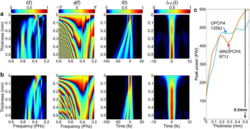
www.nature.com/scientificreports/
Amp 1 Amp 2 Amp 3 Amp 4 Amp 5
Crystal type Type I LBO
Crystal aperture (mm2) 5×5 20 × 20 130 × 130 130 × 130 130 × 130
Crystal length (mm) 22.4 12.5 12 4.2 2.6
Pump spectrum (nm) 527
Pump beamlet 1 angle (°) θ = 90, ϕ = 13.12a
Pump beamlet 2 angle (°) θ = 90, ϕ = 12.90a
Pump beamlet duration (ns) 1
Pump duration (ns) 2
Pump total energy (J) 0.3 10 500 1000 2000
Pump intensity (GW/cm2) 0.6 1.25 1.48 2.96 5.92
Signal spectrum range (nm) 670–1130
Signal angle (°) θ = 90, ϕ = 12.00a
Signal duration (ns) 2
Input signal energy (J) 0.0001 0.09 3.52 182 573
Output signal energy (J) 0.09 3.52 182 573 1,387
Table 2. Parameters in each amplifier from Amp 1 to Amp 5. a For the phase-matching optimization, see
Supplementary material.
phase of the whole laser system to generate a Fourier transform-limited (FTL) pulse after the nano-second
compressor. A temporal contrast improvement device, e.g. a cross-polarized wave (XPW) device, could be also
installed for generating an ultra-clean seed pulse50,51. This broad-band nanosecond pulse is sent to the WNOP-
CPA amplification chain as the signal beam for optical parametric amplification.
The WNOPCPA amplification chain includes five-stage amplifiers of Amp 1-Amp 5. As shown in the inset
of Fig. 2 for one of the amplifiers (top view), the pump beam is divided into two beamlets and imaged onto the
nonlinear crystal by a pair of cylindrical lens-arrays and a cylindrical Fourier lens. Because WNOPCPA has two
pumping directions in this configuration, two phase-matching conditions are satisfied simultaneously, broaden-
ing the gain spectrum of the signal. A time delay is introduced between the two pump-beamlets to completely
avoid the pump interference, which may otherwise modulate the signal beam and even damage the nonlinear
crystal. Since the two-beamlet pump is required only in the phase-matching plane, a cylindrical (not spherical)
lens-array pair and a cylindrical (not spherical) Fourier lens are utilized. For the image relay in the orthogonal
propagation plane, another cylindrical lens pair can also be inserted into the setup, like the slit spatial filter
developed for high-energy laser systems52. After five-stage WNOPCPA, the duration of the amplified high-energy
ultra-broadband nano-second chirped-pulse is restored by a nano-second compressor formed by four large-
aperture gold or hybrid gold-dielectric reflection gratings. The residual high-order dispersion is pre-compensated
by the spectral phase controlling device at the front-end. The output of the near-FTL high-energy pulse is then
delivered to the post-compression, where the spectrum is further broadened by the nonlinear propagation in
a large-aperture thin glass wafer, and the generated chirped pulse is compressed by the large-aperture chirped
mirrors. The compressed EW-class laser beam is sent to an experimental platform for exploration of ultra-high
field, ultra-fast sciences.
Broadband amplification with WNOPCPA. The five-wave (one signal, two pumps and two idlers) opti-
cal parametric coupling is simulated using the following parameters. In the spectral domain, the pump wave-
length is 527 nm and the spectrum of the signal at least covers the range of 670–1130 nm. In the temporal
domain, the pulse duration of each pump-beamlet is 1 ns with a 1 ns time delay between them resulting in
the total duration of 2 ns for the two-beamlet pump, and accordingly the pulse duration of the chirped signal
(670–1130 nm) is 2 ns. In the spatial domain, the signal and pump beams in Amp 1-Amp 5 have flattop square
apertures with a side length of 5, 20, 130, 130 and 130 mm, respectively. The total energies of the pumps for Amp
1-Amp 5 are 0.3, 10, 500, 1000 and 2000 J, respectively, which in each amplifier are equally distributed to two
pump-beamlets. In Amp 1-Amp 5, type-I LBO crystals are used, because the LBO crystal can be grown in larger-
x–y plane is chosen as the phase-matching plane (θ = 90°), and the propagation angles ϕ (angles from the optical
sizes and has higher damage-threshold compared with the BBO crystal53. In the type-I LBO (biaxial) crystal, the
x-axis) of the two pump and one signal beams are 13.12°, 12.90° and 12.00° respectively. The optimization of
the phase-matching is given in Supplementary material. Here, we choose the phase-matching direction with
a smaller signal propagation angle (compared with those of two pumps), because the angle-gap between two
pump-beamlets is enlarged54,55. These parameters together with other parameters are summarized in Table 2.
Figure 3 shows the simulation results of the evolutions of the spectral intensity and the nonlinear spectral
phase of the signal beam, and the energies of the pump, signal and idler beams along propagation in the nonlin-
ear crystals. Figure 3a shows the signal spectrum is composed of two separated components due to two discrete
pumping directions, and Fig. 3b shows the corresponding nonlinear spectral phase (or called optical parametric
phase). The linear phases due to dispersion in the stretcher and the crystal material have been removed in Fig. 3b,
in order to directly observe the evolution of the nonlinear spectral phase of the signal. As shown in Fig. 3d, the
Scientific Reports | (2021) 11:151 | https://doi.org/10.1038/s41598-020-80435-6 4
Vol:.(1234567890)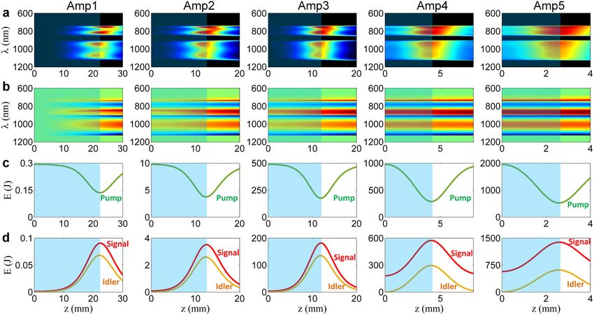
www.nature.com/scientificreports/
Figure 3. Evolution of the WNOPCPA amplification chain. Evolutions of (a) spectrum and (b) nonlinear
spectral phase of signal, and energies of (c) pump and (d) signal and idler in nonlinear crystals along
propagation z from Amp 1 to Amp 5. Blue areas show the optimized crystal lengths.
energy of the signal beam becomes maximum of 0.09, 3.52, 182, 573 and 1,387 J in Amp 1-Amp 5 at the crystal
length of z = 22.4, 12.5, 12, 4.2 and 2.6 mm, respectively. The highest efficiency of parametric amplification is
obtained by optimizing the crystal thicknesses at these values. The energy of the signal beam at the output of
Amp 5 reaches 1,387 J, which is 39.5% of the total pump energy of 3,510 J. The signal beam is expanded from
130 mm × 130 mm to 980 mm × 980 mm before the nano-second compressor to reduce the energy fluence
to ~ 0.15 J/cm2 (on the beam cross-section) at the first grating and ~ 0.1 J/cm2 (on the beam cross-section) at the
fourth grating, in order to avoid the possible damage of the fourth compressor gratings which have the measured
damage threshold of around 0.15–0.8 J/cm2 (on the grating surface) for femtosecond p ulses56.
Figure 4 shows the spectra and the nonlinear spectral phases of the signal beam at the input to Amp 1 (i.e.,
output of the front-end) and at the outputs of Amp 1-Amp 5. The amplified signal has two separated spec-
tral components of 730–860 nm and 900–1130 nm, corresponding to the two different pumping directions in
WNOPCPA. Although the spectrum of the amplified signal is not continuous, these separated components
are still coherent since they are amplified from the same coherent seed. The nonlinear spectral phase increases
gradually from Amp 1 to Amp 5 and becomes approximately 4π rad (in peak-to-valley) at the output, and this
spectral phase distortion is still within the control range of the available device for spectral phase control46–49.
In the pulse compression, most of the temporal dispersion is removed by the nano-second grating compressor,
and the residual high-order dispersion is pre-compensated by the spectral phase controlling device at the front-
end. Referring to the available meter-sized gold or hybrid gold-dielectric reflection gratings, the throughput
efficiency of the nano-second grating compressor is chosen as 70%. A FTL pulsed beam with a pulse energy of
971 J, a pulse duration (FWHM) of ~ 8.0 fs, a beam aperture of 980 mm × 980 mm, and a broadband spectrum
as shown in Fig. 4f is injected to the post-compression.
The upper label of Fig. 4 also shows the pulse overlap between the pump (green dash line) and the signal
(black solid line) in time. The pump 2 and the corresponding signal spectral component of 900–1130 nm perfectly
overlaps in time. While due to a narrow gain bandwidth, the temporal overlap between the pump 1 and its cor-
responding signal spectral component of 730–860 nm is not high, which wastes part pump energy and accord-
ingly reduces the conversion efficiency of the WNOPCPA. In order to compare this (low-energy) WNOPCPA
with the (high-energy) OPCPA, in Supplementary material we have optimized type-I LBO-based and single
beam pumped OPCPA with the broadest gain spectrum. Supplementary material also gives the re-simulation
of a five-stage OPCPA amplification chain with the perfect pump-signal temporal overlap and the same pump
energy of 0.3, 10, 500, 1000 and 2000 J in each amplifier. In this case, the amplified energy reaches 1940 J with the
FTL pulse energy of 1358 J after the nano-second grating compressor (70% efficiency) which is higher than the
amplified energy of 971 J obtained with WNOPCPA. These two different configurations of WNOPCPA (971 J)
and OPCPA (1,358 J) are compared in the following post-compression.
Spectral broadening with thin‑plate post‑compression. High-quality, large-aperture substrate
wafers are available due to mass production in industry. Their thickness generally varies from 0.2 to 10 mm with
the aperture sizes from 10 mm to 1 m and the surface roughness of less than 1 nm. The materials include fused
Scientific Reports | (2021) 11:151 | https://doi.org/10.1038/s41598-020-80435-6 5
Vol.:(0123456789)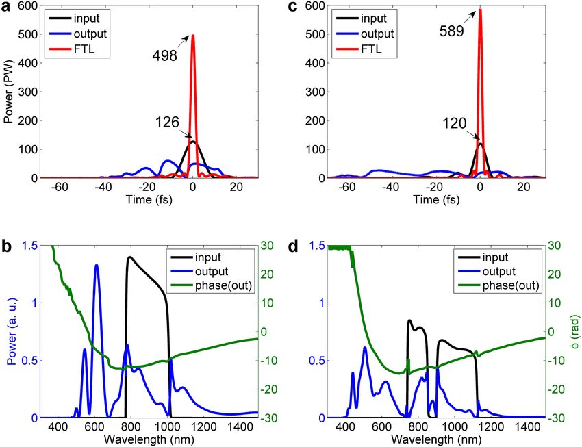
www.nature.com/scientificreports/
Figure 4. Spectrum and nonlinear spectral phase at each stage. Spectrum (black solid line) and nonlinear
spectral phase (green solid line) of signal at (a) input and (b–f) outputs of Amp 1–5, respectively. Chirped signal
pulses (black solid line) and two pump pulses (green dash line) in time are illustrated by upper labels. Pump 1
and pump 2 are two beamlets of the pump.
silica, quartz, sapphire, and other glasses. Among these materials, a meter-sized fused silica wafer is very suitable
for the post-compression of an ultra-intense laser due to its high damage-threshold, moderate nonlinear refrac-
tive index and dispersion coefficients.
The evolution of the high intensity FTL pulse in a fused silica thin wafer is analyzed for two inputs from 971 J
output of WNOPCPA and 1358 J output of OPCPA, respectively. For comparison, we assume that the 971 J input
have a square aperture of 980 mm × 980 mm and the 1,358 J input has a linearly increased square aperture of
1160 mm × 1160 mm (for the same energy fluence), all with flat-top beams but different spectra. The input inten-
sity at the fused silica thin wafer cannot be too high (lead to conical emission and even dielectric breakdown)
or too low (weaken spectral broadening), and here it is kept at around 10 TW/cm2, because at this intensity the
multiphoton-induced plasma density in fused silica is safely below the documented avalanche plasma density57.
The spectrum of WNOPCPA is shown in Fig. 4f, which possesses two spectral components of 730–860 mm and
900–1130 nm, while that of OPCPA has only one broadband spectral component of 765–1020 mm due to a single
pump beam (see Supplementary material). The simulations are made with the following parameters: the center
wavelength λ0 = 950 nm, the refractive index n = 1.4511, the GVD β2 = 24.759 fs2/mm, the TOD β3 = 34.840 fs3/
mm, the nonlinear refractive index n2 = 3.67 × 10⁻¹⁶ cm2/W, and the Raman response time TR = 4.2 fs58. Because
the fused silica wafer is very thin (less than 1 mm), the attenuation α is chosen as 0. We use a constant Raman
response time TR of 4.2 fs for linear approximation in this paper, since the sensitivity of the spectral profile to
Figure 5a,b show the evolutions of the spectrum I(f), the spectral phase ϕ(f), the pulse I(t) and the calculated
slight variation of the Raman response time TR is very low31,58.
FTL pulse IFTL(t) [calculated from the spectrum I(f)] during propagation in a thin fused silica wafer, for the
FTL input pulses from WNOPCPA and OPCPA, respectively. Comparison of Fig. 5a,b shows that the spectral
broadening is enhanced (due to the separated two spectral components of the input pulse), the pulse is more
stretched (due to a broader spectrum) and the FTL pulse width is shorter (also due to a broader spectrum)
for WNOPCPA, whereas the spectral phase evolutions for two cases are not significantly different. Figure 5(c)
illustrates the dependence of the peak-power of the FTL pulse IFTL(t) on the thickness of the fused silica, which
is expected after the perfect dispersion compensation. Although the peak-powers of the input pulses from
WNOPCPA (971 J) and OPCPA (1358 J) are close to each other, the difference among the expected FTL peak-
powers increases sharply with the thickness of the fused silica, especially after ~ 0.35 mm.
Figure 6 shows the pulses, the spectra, and the spectral phases after a 0.5 mm-thick fused silica for the input
pulses from OPCPA (1358 J) and WNOPCPA (971 J), respectively. The FTL pulses which we can expect after the
perfect dispersion compensation are also illustrated by red curves. In the OPCPA(1358 J)—post-compression, the
expected peak-power of the FTL pulse will increase from 126 to 498 PW, because the pulse duration (FWHM)
is reduced from around 11.0 fs to 2.7 fs (see Fig. 6a). And, in the WNOPCPA(971 J)—post-compression, the
expected peak-power of the FTL pulse will increase from 120 to 589 PW, because the pulse duration (FWHM)
is reduced from around 8.0 fs to ~ 1.65 fs (see Fig. 6c). This peak-power attained with the WNOPCPA—post-
compression is higher than that of the OPCPA—post-compressions.
Scientific Reports | (2021) 11:151 | https://doi.org/10.1038/s41598-020-80435-6 6
Vol:.(1234567890)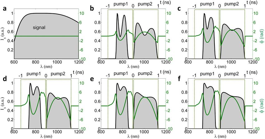
www.nature.com/scientificreports/
spectral phase ϕ(f), pulse I(t), and the FTL pulse IFTL(t) during propagation in fused silica wafer for input pulses
Figure 5. Nonlinear spectral broadening, pulse compression, and comparison. Evolution of spectrum I(f),
from (a) WNOPCPA and (b) OPCPA, respectively. (c) shows peak-power of the FTL pulse as a function of fused
silica thickness for OPCPA (1,358 J) (blue) and WNOPCPA (971 J) (orange). FTL, Fourier-transform-limit.
Comparison of Fig. 6b,d shows that the spectral broadening in the post-compression is significantly enhanced
with WNOPCPA, resulting in a shorter pulse duration and then a higher peak-power of the compressed pulse,
although the pulse energy of WNOPCPA is lower than that of OPCPA. The output spectral phases of the post-
compression for two cases are illustrated, which have quite similar profiles.
Dispersion compensation with chirped mirrors. The spectral phase (or dispersion) compensation by
the chirped mirrors is a key process for this concept, since which directly determines the performance of the
pulse compression and the peak-power. The spectral phase of a chirped pulse can be written as the Taylor expan-
sion about the center angular frequency ω0 in the frequency domain,
φ(ω) = φ0 + φ1 (ω − ω0 ) + φ2 (ω − ω0 )2 + φ3 (ω − ω0 )3 + · · · , (1)
where, ϕ0, ϕ1, ϕ2 and ϕ3 are the derivatives of the phase with respect to the angular frequency ω, corresponding
to the initial phase, the group delay, the group velocity dispersion (GVD) and the third order dispersion (TOD),
respectively. The first two terms do not influence the pulse profile, whereas the second two of GVD and TOD do.
In general, the chirped mirrors are used for broadband GVD control31,59,60. Using the spectra and spectral
phases of the pulses after propagation in a 0.5 mm-thick fused silica shown in Fig. 6b for OPCPA (1358 J) and in
Fig. 6d for WNOPCPA (971 J), we have evaluated the peak-powers of the compressed pulses by varying GVD,
with the results shown in Fig. 7a(i),b(i), respectively. The pulse reaches the highest peak-power of 260 and 268
GVD is ϕ2 = -12.5 fs2 for OPCPA and ϕ2 = -17.0 fs2 for WNOPCPA, respectively. Figures 7(a)(ii) and 7(b)(ii)
PW for the OPCPA(1358 J)—post-compression and WNOPCPA(971 J)—post-compression, respectively, when
show the residual spectral phases as well as the spectra. Figure 7a(iii),b(iii) show the compressed pulses (here
named as GVD-free (GDF) pulses) and the FTL pulses we can expect by the perfect dispersion compensation.
Recently the dispersion compensation up to TOD by chirped mirrors became possible since the TOD chirped
mirrors can introduce net TOD without introducing any additional G VD61. Then, we have re-evaluated the
peak-powers of the compressed pulses by varying both GVD and TOD for OPCPA (1,358 J) and for WNOPCPA
(971 J), with the results shown in Fig. 7c(i),d(i), respectively. With the optimized highest peak-powers, Fig. 7c(ii),
(iii), d(ii), (iii) show the spectra, residual spectral phases, compressed pulses [here named as TOD-free (TDF)
pulses], and the FTL pulses we can expect by the perfect dispersion compensation. The TDF pulses reach their
post-compression at the combinations of (ϕ2 = − 7.7 fs2, ϕ3 = − 2.47 fs3 for OPCPA) and (ϕ2 = − 5.27 fs2, ϕ3 = − 2.64
highest peak-powers of 346 and 442 PW for the OPCPA(1358 J)—post-compression and WNOPCPA(971 J)—
fs3 for WNOPCPA), respectively.
In both cases of the dispersion compensation up to GVD or TOD, the WNOPCPA—post-compression results
in a slightly higher peak-power, although WNOPCPA supplies a lower input pulse energy of 971 J than OPCPA
does (1358 J). The result shows the clear advantage of a broader spectrum. However, the above highest peak-
power of the optimized compressed pulses is still much lower than that of the FTL pulse. The FTL compressed
Scientific Reports | (2021) 11:151 | https://doi.org/10.1038/s41598-020-80435-6 7
Vol.:(0123456789)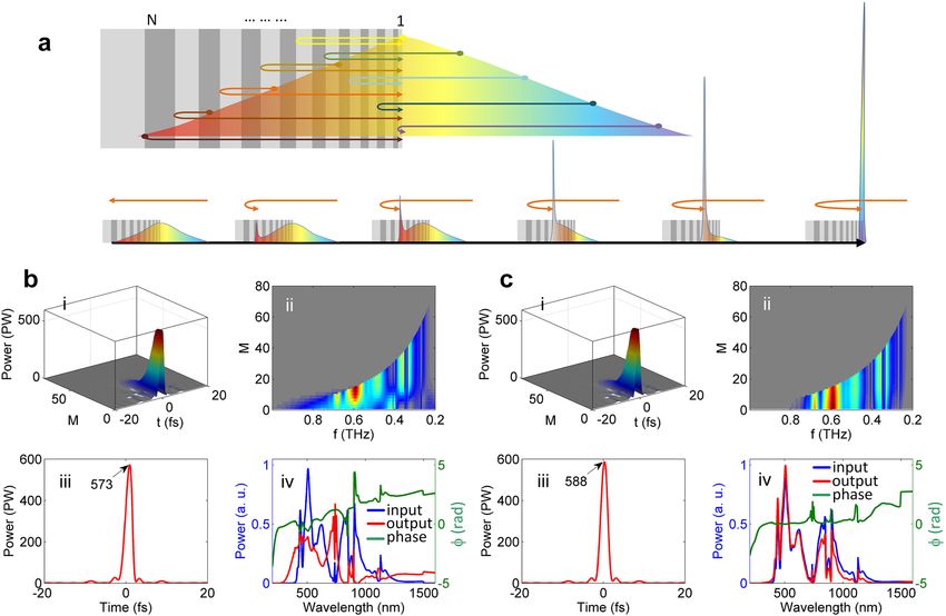
www.nature.com/scientificreports/

                                            Figure 6.  Input and output of thin wafer in time and spectrum. Post compression with a 0.5 mm-thick fused
                                            silica wafer for inputs from (a,b) OPCPA and (c,d) WNOPCPA. (a,c) show input (black), output (blue) and the
                                            FTL-compressed (red) pulses, and the unit of marked peak-powers is PW. b,d) show input (black) and output
                                            (blue) spectra and output spectral phase (green). FTL, Fourier-transform-limit, and PW, petawatt.

                                            pulse in technology right now could be generated by using the double (or more) chirped mirrors which can
                                            introduce well-controlled ultra-broadband dispersion to perfectly match a dispersion-distorted ultra-short pulse
                                            as introduced in Ref.62. In this case, the perfect pulse compressions illustrated by red curves in Fig. 7 are possible
                                            by implementing careful engineering.

                                            Discussion
                                            Limitation at the grating compressor.             The grating compressor is the bottleneck restricting the develop-
                                            ment of the current PW lasers and the future EW lasers, where the low damage threshold of the gratings limits
                                            the energy fluence of laser beams. In this case, high-energy pulse compression requires very large gratings,
                                            affecting both optical engineering and economic cost. The damage mechanism shows the damage thresholds of
                                            current gratings for 8–15 fs ultrafast laser pulses, which center at the same wavelengths, are the same. Thereby,
                                            for the same compressed pulse energy limited by the grating size, a shorter pulse duration means a higher peak-
                                            power. This is the very reason why we choose the LBO crystal instead of the DKDP crystal here, because LBO
                                            can support a broader gain spectrum than DKDP, although DKDP (~ 400 mm) currently is larger than LBO
                                            (~ 150 mm). Here we are not challenging the approach of developing DKDP-based high-energy ultra-intense
                                            lasers, where the coherent beam combination is now tried to break through the limitation of the grating com-
                                            pressor.

                                            Damage and optical nonlinearity in chirped mirrors. For an EW-class laser, the damage and the opti-
                                            cal nonlinearity in the chirped mirrors should be carefully considered. The potential damage of the chirped mir-
                                            rors can be avoided by expanding the beam aperture, thus reducing the energy fluence. Since the beam aperture
                                            in the post-compression is 980 mm × 980 mm and 1160 mm × 1160 mm for the 971 J (WNOPCPA) and 1358 J
                                            (OPCPA) input, respectively, the energy fluence at the chirped mirrors is around 0.1 J/cm2 which is lower than
                                            the measured 1-on-1 damage threshold of 0.13 ± 0.01 to 0.28 ± 0.02 J/cm263.

          Scientific Reports |   (2021) 11:151 |                 https://doi.org/10.1038/s41598-020-80435-6                                                     8

Vol:.(1234567890)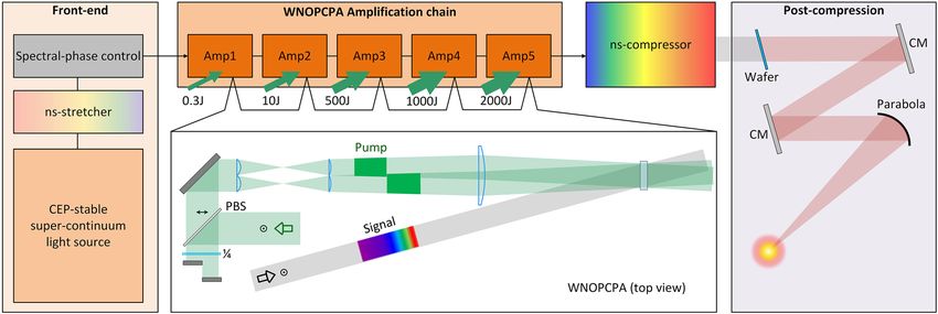
www.nature.com/scientificreports/

                                  Figure 7.  Different dispersion compensations with chirped mirrors. Dispersion compensation up to (a,b)
                                  GVD and (c,d) TOD for (a,c) OPCPA—post-compression and (b,d) WNOPCPA—post-compression,
                                  respectively. (i) shows dependence of peak-power on (a,b) GVD (ϕ2) and (c,d) GVD (ϕ2) and TOD (ϕ3), and the
                                  dispersion value for the highest peak-power is marked. (ii) shows spectrum (blue) and residual spectral phase
                                  of compressed pulse with the highest peak-power. (iii) shows compressed pulse corresponding to the highest
                                  peak-power, the FTL (red) pulse is given for reference, and the unit of marked peak-powers is PW. GVD, group
                                  velocity dispersion; TOD, third-order dispersion; FTL, Fourier-transform-limit; and PW, Petawatt.

Scientific Reports |   (2021) 11:151 |                https://doi.org/10.1038/s41598-020-80435-6                                              9

                                                                                                                                         Vol.:(0123456789)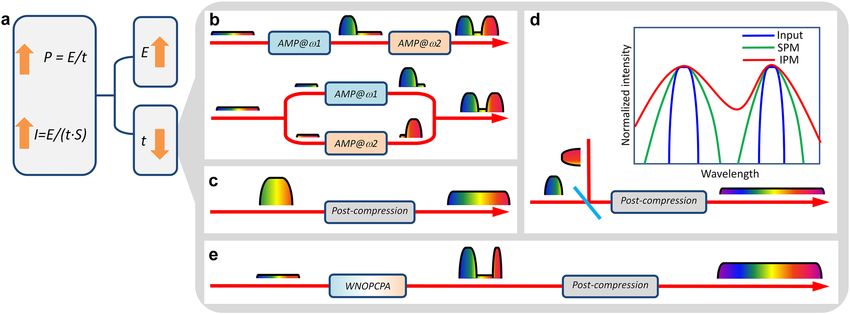
www.nature.com/scientificreports/
Figure 8. Nonlinearity in chirped mirror, and comparison. (a) Schematic diagram of pulse compression with a
chirped mirror, where light with different wavelengths have different propagation paths. (b,c) show simulation
results for WNOPCPA—post-compression with chirped mirrors composed of S iO2/TiO2 and SiO2/HfO2 layer
pairs, respectively. In (b,c), (i) and (ii) illustrate evolutions of temporal and spectrum profiles of backward-
propagating pulse in layers from M = 80 to 1, respectively, (iii) shows output pulse (the unit of marked peak-
powers is PW), and (iv) shows input (blue) and output (red) spectra and output spectral phase (green). The
layers are numbered as M = 1 to M = 80 from the surface to the deepest. PW, petawatt.
The optical nonlinear effect in a chirped mirror under irradiation of an ultra-intense, ultra-broadband laser
pulse has not been well studied so far. Figure 8a schematically shows how a laser pulse composed of different
wavelengths propagates in a chirped mirror, where different wavelength components propagate over different
optical paths, thus experiencing different group delays [i.e., group delay dispersion (GDD)]. In this propagation,
the optical nonlinearity in the chirped mirror structure could induce an extra spectral phase and also distort the
spectral amplitude, thus affecting the pulse compression. The effect of the optical nonlinearity in a chirped mirror
is estimated with the following simplified model. We assume that the chirped-mirror structure introduces the
perfect GDD profile to match the dispersion of the input pulse. Figure 8a shows that the dispersion compensation
begins with the reflection of the red component (the temporal leading edge) at the deepest layer. The reflected
backward-propagating red component temporally and spatially overlaps with the shorter wavelength component
in another layer. During the backward propagation, the bandwidth of the reflected pulse increases gradually and
the dispersion of the input pulse is completely removed at the surface of the chirped mirror, where all wavelengths
of the input pulse are contained in the reflected pulse. In the simulation, the material dispersion in the backward
propagation of the reflected pulse is not included for simplification because the thickness of the chirped mir-
ror is very small (generally 10–20 μm), and only GDD induced by the chirped Bragg structure is considered.
Then we calculate the optical nonlinearity induced only by the reflected backward-propagating pulse, which
has a sharp profile with very high peak-intensity, especially near the surface of the chirped mirror, as shown
in Fig. 8a,b(i),c(i). The simulation result shown in Fig. 8b is based on an ideal chirped mirror of 80 alternating
layers (i.e., 40 layer pairs) of S iO2 and T
iO2, covering the wavelength region of 300–1500 nm. The S iO2 and T
iO2
have the refractive indices of n = 1.4511 and 2.4920, and the nonlinear refractive indices of n2 = 3.67 × 10⁻¹⁶ and
9.4 × 10⁻¹⁵ cm2/W, respectively. The thickness of the layer pair is assumed to increase linearly from the surface
layer pair to the deepest layer pair for simplification. Figure 8b(i) shows that the peak-power of the backward-
propagating pulse increases slowly in the deep layers but increases rapidly as it propagates closer to the surface.
Figure 8b(ii) shows that the bandwidth of the backward-propagating pulse gradually increases from the deepest
layer to the surface layer, finally covering the whole spectrum of the input pulse. There are rapid spectral varia-
tions near surface from the M ~ 20 to M = 1 layers. Figure 8b(iii) shows the output pulse, and Fig. 8b(iv) shows
the spectra of the input and output pulses and the output spectral phase. The peak-power is reduced from 589
Scientific Reports | (2021) 11:151 | https://doi.org/10.1038/s41598-020-80435-6 10
Vol:.(1234567890)www.nature.com/scientificreports/
Figure 9. Pulse energy fluctuation effect. For (a,b) OPCPA—post-compression and (c,d) WNOPCPA—post-
compression, when relative intensity changes induced by input energy fluctuation are η = 0.9, 1 and 1.1, (a,c)
pulse and (b,d) spectrum and phase at different propagation positions, (i) at input, (ii) after thin wafer, (iii)
after chirped mirrors [with TOD dispersion compensation (TDC) at η = 1], and (iv) after chirped mirrors [with
perfect dispersion compensation (PDC) at η = 1]. Peak-power of TDC and PDC compressed pulses as a function
of η for (e) OPCPA—post-compression and (f) WNOPCPA—post-compression, respectively.
PW to around 573 PW due to distortions of both spectral amplitude and phase (arising from SPM mainly in the
TiO2 layers), especially the spectral phase at the longer wavelength region which experiences longer propagation.
This adverse effect can be reduced by replacing T iO2 by HfO2, which has n = 2.0851 and n2 = 5.8 × 10⁻¹⁶ cm2/W,
respectively. Note that n2 of HfO2 is about 16 times smaller than that of T iO2. The simulation results are shown in
Fig. 8c. Comparing Fig. 8c(i), (ii) with Fig. 8b(i), (ii) respectively, the peak-power of the backward-propagating
pulse reaches a higher value, and the spectral variation near the surface (e.g., from M ~ 20 to M = 1 layers) disap-
pears. Figure 8c(iii) shows that the compressed pulse almost has no distortion, reaching the nearly ideal peak-
power of 588 PW. Figure 8c(iv) shows that the difference between the input and the output spectra is negligible
and the spectral phase distortion is small. Based on these comparisons, we conclude that low-nonlinearity-
material (e.g., SiO2/HfO2) chirped mirrors are more suitable for the ultra-intense pulse compression.
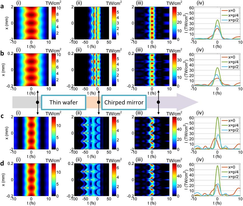
Spatial intensity modulation in post‑compression. In the above, it is assumed that the input laser to
the thin-plate post-compression has a stable pulse energy and a flat-top beam. Here, we consider the effects of
the pulse energy fluctuation and the spatial intensity non-uniformity on the post-compression.
We first consider the pulse energy fluctuation, and show the simulation results for the OPCPA-post-compres-
sion and the WNOPCPA—post-compression in Fig. 9a–d, respectively, for comparison. When the input laser
has ± 10% energy fluctuation, the relative input intensity changes as η = 0.9, 1 and 1.1, where η = 1 corresponds
to the ideal case [i.e., Figs. 6(a), 6(b) and 6(c), 6(d) for two configurations, respectively]. Figure 9a,c show pulses,
Scientific Reports | (2021) 11:151 | https://doi.org/10.1038/s41598-020-80435-6 11
Vol.:(0123456789)www.nature.com/scientificreports/
and Fig. 9b,d show the corresponding spectra and spectral phases. Subfigures (i), (ii), (iii), and (iv) in Fig. 9a–d
respectively show the results at the input, after nonlinear propagation in the 0.5 mm-thick fused silica thin
wafer, after the chirped mirror with up to TOD dispersion compensation at η = 1, and after the chirped mirror
with perfect dispersion compensation at η = 1, where the nonlinear propagation is changed by the change of the
input intensity. Here, we assume chirped mirrors introduce spatially uniform dispersion compensation at η = 1.
Subfigures (iii) and (iv) in Fig. 9a,c show that the peak-power is reduced, no matter when η is increased to 1.1
or reduced to 0.9. This mainly arises from the change of the spectral phase and the spectrum due to the change
of the input intensity [see Fig. 9b(ii),d(ii)], which breaks the dispersion-matching with the chirped mirrors
[see (iii) and (iv) in Fig. 9b,d]. Figure 9e,f show the dependence of the final peak-power (with both TOD and
perfect dispersion compensations at η = 1) on the relative input intensity change η induced by the input energy
fluctuation for two configurations. Comparing with the OPCPA-post-compression, although the sensitivity is
higher for the WNOPCPA—post-compression, the averaged peak-power for different shots linearly varying
from η = 0.9 to 1.1 is still stronger. With TOD dispersion compensation at η = 1, the averaged peak-power is
312 PW for the OPCPA-post-compression and 428 PW for the WNOPCPA-post-compression; and with per-
fect dispersion compensation at η = 1, which is 369 PW for the OPCPA-post-compression and 458 PW for the
WNOPCPA-post-compression. If the energy fluctuation can be well controlled, e.g., ± 5%, the performance of
the WNOPCPA—post-compression can be even better.
We next consider the spatial intensity non-uniformity, and the simulation results for the OPCPA—post-
compression and the WNOPCPA—post-compression are shown in Fig. 10a,b and Fig. 10c,d, respectively, for
comparison. The modulation of the spatial intensity non-uniformity is assumed to have a cosine-function-like
profile of M⋅cos(x/p) + 1, where M is a coefficient, x is the transverse coordinate, and p is the spatial period.
When the coefficient M is 0.1, the relative intensity change η across the beam aperture varies between 0.9 and 1.1
(i.e., ± 10%), where η = 1 corresponds to the ideal case (i.e., Fig. 6a–d for two configurations, respectively). The
spatial period p in Fig. 10a–d is 1 mm (i.e., slow-spatial variation) and 0.1 mm (i.e., fast-spatial variation), respec-
tively, showing small-scaled self-focusing in different spatial scales. Subfigures (i), (ii), and (iii) in Fig. 10a–d
respectively show the 2-D spatiotemporal intensity distributions at the input, after the nonlinear propagation in
the 0.5 mm-thick thin fused silica wafer, and after the chirped mirror with spatially uniform perfect dispersion
compensation at η = 1. Subfigures (iv) in Fig. 10a–d show three compressed pulses at three typical positions
across the beam aperture. Subfigures (i) and (ii) in Fig. 10a–d show the spatial intensity non-uniformity after
the fused silica is increased, which arises from different nonlinear propagations induced by different input
intensities. Subfigures (ii) and (iii) in Fig. 10a–d show the spatial intensity non-uniformity after the chirped
mirror is further increased, which arises from dispersion-mismatching with the chirped mirror. Subfigures (iv)
in Fig. 10a–d show, at the positons of x = 0, p/4, and p/2 (i.e., the relative intensity changes of η = 1.1, 1.0, and
0.9), whether the increasing or the decreasing of the intensity distorts the compressed pulse. Because the change
of the intensity changes nonlinear propagation in the fused silica, which breaks dispersion-matching with the
following chirped mirror. Comparing Fig. 10 (c)(iv) with Fig. 10(a)(iv) or Fig. 10(d)(iv) with Fig. 10(b)(iv), the
distorted pulses for two configurations have almost the same peak-values, although the sensitivity is higher for
the WNOPCPA—post-compression. By integrating the peak-intensity across the beam aperture, for the slow-
spatial variation of p = 1 mm, the average power-power is 403 PW for the OPCPA-post-compression and 420
PW for the WNOPCPA-post-compression; and for the fast-spatial variation of p = 0.1 mm, which is 355 PW
for the OPCPA-post-compression and 389 PW for the WNOPCPA-post-compression. The WNOPCPA-post-
compression still has a slightly better performance. The difference between Fig. 10a,b or Fig. 10c,d, i.e., between
slow-spatial variation (p = 1 mm) and fast-spatial variation (p = 0.1 mm), is due to small-scaled self-focusing,
which further distorts the compressed pulses [comparing Fig. 10b with Fig. 10a or Fig. 10d with Fig. 10c. The
spatial frequency of small-scaled self-focusing that can generate obvious degradation is very high (e.g., p = 0.1 mm
here), which can be reduced by adding a spatial filter before the post-compression (see details in Ref.31).
Finally, it is noted that the spectral phase of nonlinear propagation in the thin fused silica wafer is dynamical
(influenced by the input intensity), while that of the chirped mirrors is constant, and the result is the disper-
sion-matching between nonlinear propagation and chirped mirror is broken. This shows that the pulse energy
fluctuation and the spatial intensity non-uniformity of the input laser beam have to be highly controlled. Here,
the pulse compression is much more sensitive to the change in the spectral phase than the spectral amplitude,
although the intensity change also influences the output spectrum.
Other engineering considerations. In the WNOPCPA presented in this paper, we have reduced the
number of pump-beamlets from four in our previous w ork45 to only two. This leads to two advantages: the pump
interference is avoided completely and the conversion efficiency from the pump to the signal is improved. The
amplified pulse with two separated spectra enhances the spectral broadening in the post-compression, eventu-
ally generating a continuous ultra-broadband spectrum. We note that the coherence between the two separated
amplified-spectra is maintained since they directly come from a single coherent pulse and no extra spatial or
temporal separation (e.g., beam or pulse separation and/or combination) is introduced.
As discussed in the above, the precise dispersion compensation by chirped mirrors for generation of the
FTL pulse in the post-compression is essential and feasible. The fabrication of the meter-sized chirped mirrors
is still an engineering challenge, although the combination of double (or more) chirped mirrors could realize
the required perfect dispersion compensation.
Also, as discussed in the above, the pulse energy fluctuation and the spatial intensity non-uniformity of the
laser beam have to be well controlled to reduce the nonlinear phase variation induced in the post-compression.
In order to achieve a flattop signal beam in OPCPA and/or WNOPCPA, the beam smoothing technologies should
be considered in the pump beam in the future64.
Scientific Reports | (2021) 11:151 | https://doi.org/10.1038/s41598-020-80435-6 12
Vol:.(1234567890)www.nature.com/scientificreports/
Figure 10. Spatial intensity non-uniformity effect. For (a,b) OPCPA—post-compression and (c,d)
WNOPCPA—post-compression, when input beam has (a,c) slow- or (b,d) fast-variation spatial intensity
non-uniformity, spatiotemporal intensity distributions at different propagation positions (i) at input, (ii) after
thin wafer, and (iii) after chirped mirror (with perfect dispersion compensation at η = 1). Spatial intensity
non-uniformity has a cosine-function-like profile varies between 0.9 to 1.1 (i.e., ± 10%) in space, p is the spatial
period, which equals (a,c) 1 mm and (b,d) 0.1 mm, respectively. (iv) shows compressed pulses at three positions
of x = 0, p/4, and p/2 across beam, corresponding to relative intensity changes of η = 1.1, 1 and 0.9, respectively.
There are other potential problems to realize a sub-optical-cycle EW-class laser. In additions to the previously
well-studied issues such as dispersion-control, wave-front-control, high-gain/energy-amplification, spectral-
narrowing, temporal-contrast, beam-smoothing, beam-pointing, beam-focusing, etc., more recent issue of
spatiotemporal/spectral coupling distortion induced by deformation of the compressor g ratings65–68 should be
addressed, although it is technically c ontrollable69.
Conclusion and outlook
We have proposed and simulated an ultra-broadband concept for an EW-class peak-power by combining the
(two-beamlet pumped) WNOPCPA with the thin-plate post-compression. Detailed numerical analyses of the
proposed 0.5 EW laser concept, which is composed of the state-of-the-art optical components, have been pre-
sented including optical parametric amplification in the five-stage amplifiers, evolution of the spectral broad-
ening and the spectral phase in a thin fused silica wafer, and dispersion compensation by the chirped mirrors.
Effects of the nonlinearity in the chirped mirror and the spatial intensity modulation in the post-compression
are discussed. Compared with the OPCPA—post-compression configuration, a much broader spectrum and
accordingly an even shorter pulse is generated by the WNOPCPA—post-compression configuration. This concept
will be capable of generating an ultra-short, high-energy, and ultrahigh peak-power laser pulse with the spectral
Scientific Reports | (2021) 11:151 | https://doi.org/10.1038/s41598-020-80435-6 13
Vol.:(0123456789)www.nature.com/scientificreports/
coverage of 0.4–1.3 μm, the pulse duration (FWHM) of only ~ 1.65 fs, the pulse energy of 971 J, and accordingly
the peak-power of 589 PW.
The conceptual design of the 0.5 EW laser proposed in this paper is based on the largest available size of—the
type-I LBO crystal (130 mm × 130 mm) and the surface damage threshold of the LBO crystal (~ 20 GW/cm2)
which limits the pump energy in the final amplifier. In future, a real EW laser could be achieved when larger
LBO crystals, gratings, and other optics become available and/or by coherent addition of the two 0.5 EW beams
described in this paper. An EW-class laser will be a very complex system, and a lot of engineering problems need
to be considered in the future. Fortunately, since the sub-optical-cycle (less than 3 fs) intense laser pulses have
been successfully demonstrated in small-scale laser systems worldwide (see Table 1), the next step of dramatically
scaling the peak-power/intensity to an extremely high level is theoretically feasible.
Methods
Simulation of WNOPCPA. Refer to the theoretical model of the two-beam-pumped non-collinear
PCPA44, the interaction of one signal light, two pump lights and two idler lights satisfy the five-wave coupled-
O
wave equations, and, in the frequency domain, which is given by45
2
χm(2) ωs
∂As
+ iks As = −i Ap,m A∗i,m ,
∂z ns c
m=1
∂Ap,1 χ1(2) ωp 1
+ ikp,1 cos α1 Ap,1 = −i As Ai,1 ,
∂z np,1 c cos α1 cos2 (α1 − ρ)
(2)
∂Ai,1 χ1 ωi,1 (2)
+ iki,1 cos (α1 + β1 )Ai,1 = −i Ap,1 A∗s ,
∂z ni,1 c cos (α1 + β1 )
(2)
∂Ap,2 χ2 ωp 1
+ ikp,2 cos α2 Ap,2 = −i 2
As Ai,2 ,
∂z np,2 c cos α2 cos (α2 − ρ)
∂Ai,2 χ2(2) ωi
+ iki,2 cos (α2 + β2 )Ai,2 = −i Ap,2 A∗s ,
∂z ni c cos (α2 + β2 )
where, ks kp,m and ki,m are the wave vectors of signal, number m pump and number m idler (i.e., full dispersions
of the material are considered), χm is the number m second-order nonlinear coefficient which is direction-
dependent, and n is the refractive index which is wavelength and direction dependent, αm is the number m non-
collinear angle between signal and number m pump (i.e., non-collinear angle is considered), βm is the number m
angle between number m pump and number m idler which is also wavelength dependent, ρ is the pump walk-off
angle (i.e., pump walk-off is considered).
Simulation of post‑compression. In the spatiotemporal domain, the propagation of an ultra-short pulse
in a fused silica thin wafer can be approximately described by70
β2 ∂ 2 β3 ∂ 3 i ∂ |A|2 A ∂|A|2
2
∂2
∂A α i ∂ 2
=− i − + A+ + 2 A+iγ |A| + − TR A,
∂z 2 ∂t 2 6 ∂t 3 2 2n0 k0 ∂x 2 ∂y ω0 A ∂t ∂t
(3)
where z is the propagation coordinate, x and y are the transverse coordinates, A(t, z) is the slowly varying ampli-
tude of the electric field at time t and position z, β2 is GVD, β3 is TOD, α is the attenuation coefficient of the mate-
rial, γ = 2n0ε0ck0n2 is the strength of the material nonlinearity (with n0 refractive index, ε0 vacuum permittivity,
k0 wavenumber, and n2 the nonlinear refractive index), ω0 is the center angular frequency, and TR is the Raman
response time. The effects of dispersion, attenuation, diffraction, self-focusing, SPM, self-steepening and SRS are
considered. When considering the pulse energy fluctuation or the spatial intensity non-uniformity, a coefficient
of η or η(x, y) is added in the initial input intensity of I(x, y, z = 0, t), respectively.
Data availability
The data that support the findings of this study are available from the corresponding author upon reasonable
request.
Received: 21 July 2020; Accepted: 21 December 2020
References
1. Strickland, D. & Mourou, G. A. Compression of amplified chirped optical pulses. Opt. Commun. 56, 219–221 (1985).
2. Danson, C. N. et al. D. Petawatt and Exawatt class lasers worldwide. High Power Laser Sci. Eng. 7, 03000e54 (2019).
3. Li, W. et al. 339 J high-energy Ti:sapphire chirped-pulse amplifier for 10 PW laser facility. Opt. Lett. 43, 5681–5684 (2018).
4. Wills, S. ELI: Open for business. Opt. Photon. News 31(January), 32–37 (2020).
5. Zeng, X. et al. Multi-Petawatt laser facility fully based on optical parametric chirped-pulse amplification. Opt. Lett. 42, 2014–2017
(2017).
6. Wang, P. et al. High-performance seed pulses at 910 nm for 100 PW laser facilities by using single-stage nondegenerate four-wave
mixing. Opt. Lett. 44, 3952–3955 (2019).
Scientific Reports | (2021) 11:151 | https://doi.org/10.1038/s41598-020-80435-6 14
Vol:.(1234567890)www.nature.com/scientificreports/
7. Shao, B. et al. Broad-bandwidth high-temporal-contrast carrier-envelope-phase-stabilized laser seed for 100 PW lasers. Opt. Lett.
45, 2215–2218 (2020).
8. Manzoni, C. et al. Coherent pulse synthesis: Towards sub-cycle optical waveforms. Laser Photon. Rev. 9, 129–171 (2015).
9. Krauss, G. et al. Synthesis of a single cycle of light with compact erbium-doped fibre technology. Nat. Photon. 4, 33–36 (2010).
10. Cox, J. A., Putnam, W. P., Sell, A., Leitenstorfer, A. & Kärtner, F. X. Pulse synthesis in the single-cycle regime from independent
mode-locked lasers using attosecond-precision feedback. Opt. Lett. 37, 3579–3581 (2012).
11. Wirth, A. et al. Synthesized light transients. Science 334, 195–200 (2011).
12. Huang, S. W. et al. High-energy pulse synthesis with sub-cycle waveform control for strong-field physics. Nat. Photon. 5, 475 (2011).
13. Manzoni, C. et al. Coherent synthesis of ultra-broadband optical parametric amplifiers. Opt. Lett. 37, 1880–1882 (2012).
14. Chia, Sh. H. et al. Two-octave-spanning dispersion-controlled precision optics for sub-optical-cycle waveform synthesizers. Optica
1, 315–322 (2014).
15. Harth, A. et al. Two-color pumped OPCPA system emitting spectra spanning 1.5 octaves from VIS to NIR. Opt. Express 20,
3076–3081 (2012).
16. Rivas, D. E. et al. Next generation driver for attosecond and laser-plasma physics. Sci. Rep. 7, 5224 (2017).
17. Alismail, A. et al. Multi-octave, CEP-stable source for high-energy field synthesis. Sci. Adv. 6, eaax3408 (2020).
18. Nisoli, M., DeSilvestri, S. & Svelto, O. Generation of high energy 10 fs pulses by a new pulse compression technique. Appl. Phys.
Lett. 68, 2793 (1996).
19. Nisoli, M. et al. Compression of high-energy laser pulses below 5 fs. Opt. Lett. 22, 522–524 (1997).
20. Brabec, T. & Krausz, F. Intense few-cycle laser fields: Frontiers of nonlinear optics. Rev. Mod. Phys. 72, 545–591 (2000).
21. Dudley, J. M., Genty, G. & Coen, S. Supercontinuum generation in photonic crystal fiber. Rev. Mod. Phys. 78, 1135–1184 (2006).
22. Chen, X. et al. Generation of 4.3 fs, 1 mJ laser pulses via compression of circularly polarized pulses in a gas-filled hollow-core fiber.
Opt. Lett. 34, 1588–1590 (2009).
23. Adachi, S. et al. 1.2 mJ sub-4-fs source at 1 kHz from an ionizing gas. Opt. Lett. 35, 980–982 (2010).
24. Böhle, F. et al. Compression of CEP-stable multi-mJ laser pulses down to 4 fs in long hollow fibers. Laser Phys. Lett. 11, 095401
(2014).
25. Travers, J. C., Grigorova, T. F., Brahms, C. & Belli, F. High-energy pulse self-compression and ultraviolet generation through soliton
dynamics in hollow capillary fibres. Nat. Photon. 3, 547–554 (2019).
26. Ouillé, M. et al. Relativistic-intensity near-single-cycle light waveforms at kHz repetition rate. Light Sci. Appl. 9, 47 (2020).
27. Lu, Ch. H. et al. Sub-4 fs laser pulses at high average power and high repetition rate from an all-solid-state setup. Opt. Express 26,
8941–8956 (2018).
28. Hwang, S. I. et al. Generation of a single-cycle pulse using a two-stage compressor and its temporal characterization using a tun-
nelling ionization method. Sci. Rep. 9, 1613 (2019).
29. Seo, M., Tsendsuren, K., Mitra, S., Kling, M. & Kim, D. High-contrast, intense single-cycle pulses from an all thin-solid-plate setup.
Opt. Lett. 45, 367–370 (2020).
30. Voronin, A. A., Zheltikov, A. M., Ditmire, T., Rus, B. & Korn, G. Subexawatt few-cycle lightwave generation via multipetawatt
pulse compression. Opt. Commun. 291, 299–303 (2013).
31. Mourou, G. A., Mironov, S., Khazanov, E. & Sergeev, A. Single cycle thin film compressor opening the door to zeptosecond-Exawatt
physics. Eur. Phys. J. Spec. Top. 223, 1181–1188 (2014).
32. Ginzburg, V. N. et al. Influence of the cubic spectral phase of high-power laser pulses on their self-phase modulation. Quantum
Electron. 46, 106–108 (2016).
33. Ginzburg, V. N. et al. Compression after compressor: Threefold shortening of 200-TW laser pulses. Quantum Electron. 49, 299–301
(2019).
34. Farinella, D. M. et al. Focusability of laser pulses at petawatt transport intensities in thin-film compression. J. Opt. Soc. Am. B 36,
A28–A32 (2019).
35. Khazanov, E. A., Mironov, S. Y. & Mourou, G. Nonlinear compression of high-power laser pulses: compression after compressor
approach. Phys. Usp. 62, 1096–1124 (2019).
36. Mironov, S. Y. et al. Thin plate compression of a sub-petawatt Ti: Sa laser pulses. Appl. Phys. Lett. 116, 241101 (2020).
37. Ginzburg, V. et al. Fivefold compression of 250-TW laser pulses. Phys. Rev. A 101, 013829 (2020).
38. Alfano, R. R. & Ho, P. P. Self-, cross-, and induced-phase modulations of ultrashort laser pulse propagation. IEEE J. Quantum
Electron. 24, 351–364 (1988).
39. Yamashita, M., Sone, H., Morita, R. & Shigekawa, H. Generation of monocycle-like optical pulses using induced-phase modulation
between two-color femtosecond pulses with carrier phase locking. IEEE J. Quantum Electron. 34, 2145–2149 (1998).
40. Matsubara, E., Yamane, K., Sekikawa, T., & Yamashita, M. Generation of 2.6 fs optical pulses using induced-phase modulation in
a gas-filled hollow fiber. J. Opt. Soc. Am. B 24, 985–989 (2007).
41. Fang, S. B. et al. Generation of sub-900-μJ supercontinuum with a two-octave bandwidth based on induced phase modulation in
argon-filled hollow fiber. IEEE Photon. Technol. Lett. 23, 688–690 (2011).
42. Fang, S., Su, Y., Jiang, J., Liu, H., & Wei. Z. Octave spanning flat-plateau white-light generation in multi-thin plates by utilizing
self-steepening and induced phase modulation. in Paper Presented at 2019 Conference on Lasers and Electro-Optics Europe &
European Quantum Electronics Conference (CLEO/Europe-EQEC), Munich, Germany, 23–27, Jun. 2019. (IEEE Xplore: IEEE, https
://doi.org/10.1109/CLEOE-EQEC.2019.8871570, 2019).
43. Dubietis, A., Danielius, R., Tamošauskas, G. & Pisarskas, A. Combining effect in a multiple-beam-pumped optical parametric
amplifier. J. Opt. Soc. Am. B 15, 1135–1139 (1998).
44. Herrmann, D., Tautz, R., Tavella, F., Krausz, F. & Veisz, L. Investigation of two-beam-pumped noncollinear optical parametric
chirped-pulse amplification for the generation of few-cycle light pulses. Opt. Express 18, 4170–4183 (2010).
45. Li, Z. & Kawanaka, J. Possible method for a single-cycle 100 petawatt laser with wide-angle non-collinear optical parametric
chirped pulse amplification. OSA Continuum 2, 1125–1137 (2019).
46. Tournois, P. Acousto-optic programmable dispersive filter for adaptive compensation of group delay time dispersion in laser
systems. Opt. Commun. 140, 245–249 (1997).
47. Verluise, F., Laude, V., Cheng, Z., Spielmann, Ch. & Tournois, P. Amplitude and phase control of ultrashort pulses by use of an
acousto-optic programmable dispersive filter: Pulse compression and shaping. Opt. Lett. 25, 575–577 (2000).
48. Forget, N., Canova, L., Chen, X., Jullien, A. & Lopez-Martens, R. Closed-loop carrier-envelope phase stabilization with an acousto-
optic programmable dispersive filter. Opt. Lett. 34, 3647–3649 (2009).
49. Li, Z. et al. Fourth-order dispersion compensation for ultra-high power femtosecond lasers. Opt. Commun. 357, 71–77 (2015).
50. Jullien, A. et al. 10–10 temporal contrast for femtosecond ultraintense lasers by cross-polarized wave generation. Opt. Lett. 30,
920–922 (2005).
51. Chvykov, V., Rousseau, P., Reed, S., Kalinchenko, G. & Yanovsky, V. Generation of 1011 contrast 50 TW laser pulses. Opt. Lett. 31,
1456–1458 (2006).
52. Chesnut, K. et al. Entirely reflective slit spatial filter for high-energy laser systems. Opt. Express 27, 27017–27027 (2019).
53. Wagner, F. R., Hildenbrand, A., Natoli, J. & Commandré, M. Multiple pulse nanosecond laser induced damage study in L iB3O5
crystals. Opt. Express 18, 26791–26798 (2010).
Scientific Reports | (2021) 11:151 | https://doi.org/10.1038/s41598-020-80435-6 15
Vol.:(0123456789)You can also read