SMRT SARFinder SARFinder Transportable - Manual - Seasafe Systems
←
→
Page content transcription
If your browser does not render page correctly, please read the page content below
Manual

            sMRT SARFinder
               SARFinder
             Transportable

Providers of the leading Mobilarm and Sea Marshall brands of Man Overboard solutions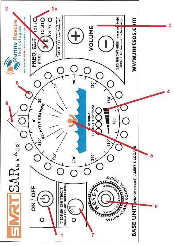
Contents

        PAGE No.             Description
               2             Declaration of Conformity
               3             Technical Data
               4             Overview
               5             Component Parts
               6             Mounting the display
              7-8            Display Key functions
               9             Installing Antenna correctly
             10-11           Electrical connections
              12             How to use the SARFINDER® Step by Step Instruction
              13             Recommended SARFINDER® Sea Trial Procedure
              14             Crewfix® NMEA Box Information
              15             Technical Data SARFINDER® Transportable System
              16             Overview SARFINDER® Transportable System
             17-18           Technical Data SARFINDER Battery Charger
             19-21           Blank Pages for notes
              22             Warranty Information

Issue 028 Dated 27/02/2014
                                                               1
Technical Data - SARFinder MKIII
Control Box Dimensions 165x95x65mm - Aluminium Box (excluding antenna & connectors)
Control Box Weight 1000gms
Mounting Options Surface 210mm x 146mm (Opt 1)
o Bracket 260mm (Opt 2) weight 1000gms
Antenna Base Dimensions 550 mm H x350mm W - PVC Plastic
Antenna Base Weight 950gms
Antenna Pole Mounting Bkt 50mm Internal Dia
Temperature range -20°C + 55°C (Operational)
Bandwidth 25 KHz
Modulation AM
Ports DC12V Power Cable (1m) Antenna Cable (20m)
Waterproofing IPX67
Sensitivity 3 dBuV/m (threshold of target bearing resolution)
Frequencies 121.5 MHz, 121.65 MHz (Test 1), 121.775 (Test 2)
Criteria of ELT/PLB recognition Audible AM down-swept tone (compliant to ITU-R M.690-2)
Audio output max. 8Vss (speaker > 8 Ohm)
Relay contact Floating, carrying capacity max. 0.5 A/10W
Current Consumption Standby = 300mA – Tracking = 850mA – Alarming 1300 mA
If alarm + ext. speaker (8 Ohm) = 400mA
Operating Voltage 12V DC (with transient compliance to ISO 7637-2)
Antenna Gain 1.4 dBi nominal
Bearing detection method Triangular phase delta
Bearing resolution accuracy 15 @ 10 dBuv/m maximum
Antenna Triple Coax Cable Impedence: 75 Ω
o Capacitance 60pF / m
o Attenuation / 10 m: 0.28 dB @ 1.5 MHz, 2 dB @ 100 MHz, 4.7 dB @ 500 MHz
o Attenuation / 100 m: 20 dB @ 100 MHz
o Diameter: 7.2 mm
o Operating temperature: –20 → +70 °C
o Coaxial Type : Triple RG179B/U
Standards Tested to: ETSI EN 301 489-1 V1.5.1 (2004-11)
o ETSI EN 301 489-22 V1.3.1 (2003-11)
3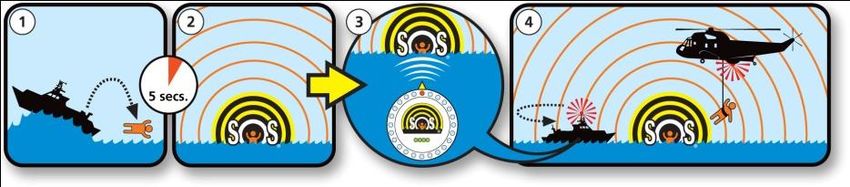
Overview
Marine Rescue Technologies Ltd. is pleased to present this manual covering the Sea Marshall® SARFinder maritime survivor
locating device receiver. The Sea Marshall® products are recognised as the industry standard for self managed safety alert &
locate safety systems for commercial use. In this booklet you will find a product overview and operator instructions for the
following products:

        SARfinder® Self managed alert / locator safety system*
        SARfinder® Transportable systems*
        *AU9 Test Frequency Beacon 121.65 MHz (required for testing and training purpose, included)
        Crewfix® NMEA Box.

So where do we start? ….What is a Maritime Survivor Locating Device?
A Maritime Survivor Locating Device is made up of 2 components which work together to create a Self-Managed Man over
Board Safety System. These 2 components are referred to as Alerting Units (beacons/PLBs) and Base Units (receivers).

NOTE – the approximate tracking ranges listed are taken from tests where the receiver antenna has been correctly installed at
the recommended height with the AU9 correctly fitted to an intelligent lifejacket. Wearing the AU9 around the neck will reduce
the tracking/alerting ranges to below the ranges listed herein.
Alerting Units are personal transmitters, or personal locator beacons worn by each crew member or passenger. There is no
restriction in the number of Alerting Units that can be used as part of a Sea Marshall® MSLD system. Below is an example of one
type of Sea Marshall® Alerting Unit. The following pages describe Base Units (receivers).

SARfinder® 1003 locating system (MKIII)

The Sea Marshall® SARfinder® locating system continuously monitors for an SOS signal from a Sea Marshall® Alerting Unit, the
system automatically alerts of a person in distress, automatically plotting the direction of the incident and allowing you to
rapidly locate the missing person without calling on the Search and Rescue Services. This system is used by professionals on a
daily basis to provide safety cover. Users included amongst others – River Pilots, Fishermen, Wind farm Operators, Geo-Survey
Companies, Offshore Oil & Gas operators,

                                                               4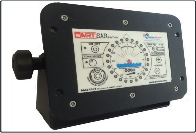
1.0 Sarfinder Component Parts
1.1 MOB Alerting Unit LIVE AU9 (Model as required sold seperately)

 (A 121.65 TEST beacon is included for training and exercise
purposes. The test beacon is identical to a live beacon with      Image shown for
the exception that they are green in colour and transmit       representation only
only on the test frequency.)

1.2 SARfinder® control box display
Dedicated Man overboard alarm / locator Base Unit.
Automatic immediate MOB alerting and tracking. LED MOB
warning indicator. Easy to operate and install with user
friendly controls. Waterproof IP-68 display. Approximate
range indicator (near or far). High quality construction.
Training frequencies 121.65MHz & 121.775MHz (TEST2).
12V Power (240V AC to 12V DC or 24V DC to 12V DC
converters available). An external siren for loud audio MOB
alerting is pre-wired to the power cable.

2.0 Antenna
Robust lightweight antenna with mounting brackets.
Comes with 20m cable, plugs, fittings and 50mm mounting
bracket.

All the above components combine to create a self managed rescue system

                                                               5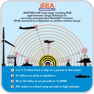
3.0 Mounting of the display unit.
3.1 The Bridge Box can be flush mounted by cutting a hole in the mounting surface. The unit can then be mounted using the
four M4 nuts and bolts provided.
3.2 The Bridge Box unit can be used with the trunnion mount adjustable bracket that it comes fitted to. It can be fixed either
above head height facing down or below head height facing up.
3.3 In either case the display                                                                                     210mm
should be mounted on a                                                                                              width
smooth and stable surface.
The back of this unit has to be
accessible for power supply
and RF antenna connectors.
Ensure that there are no
                                                                                                                             146mm
other vulnerable elements                                                                                                     height
within the mounting surface
(e.g. electric cables, gas pipes                                                                                             height

or water pipes).

        Overall height 175mm

                                                                                Width of bracket base 195mm
                                                                              Total width including hand wheels
                                                                                            260mm
                          Back section depth 55mm

                                                                6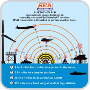
7
4.0 Display Key Functions.
ENSURE EACH CREWMEMBER IS FULLY FAMILIAR WITH ALL OF THE FOLLOWING OPERATING FUNCTIONS.
1. Power: PRESS and HOLD the ON/OFF button to activate the unit. Green LED indicates power ON.
2. Frequency Select: 1 button cycles 3 frequencies:
                   121.500 MHz = (LIVE Frequency, Internationally recognised SAR homing frequency).
2.a                121.650 MHz = Test.
                   121.775 MHz = Normally allocated for the Test 2 frequency.
                                   A GREEN LED indicator will show the user the frequency selection they have made. If after 20
                                   minutes of selecting one of the test frequencies the user has not returned to 121.5 MHz, the
                                   unit will default back to 121.5 MHz automatically.
3. Speaker Volume:                 The user will be able to adjust the speaker volume via two buttons; Volume Up and Volume
                                   Down. Reducing the volume below the audible limit turns off the speaker, increasing the
                                   volume from this point will turn the speaker back on. On power up the volume will be at its
                                   middle setting.
4 RSSI:                            The received signal strength indicator (RSSI) consists of 4 GREEN LED’s arranged horizontally
                                   in the centre of the display and gives an indication of approximate range to target.
5. RSI:                            The received signal indicator (RSI) consists of a single RED LED in the centre of the display
                                   (the little red man symbol inside the SOS logo). THIS LED COMES ON WHEN A PLB SIGNAL IS
                                   RECEIVED. As an Anti-Collision Warning indicator the RSI will FLASH ON & OFF and the four
                                   green LED’s will be lit when the target is within very close range.
6. Reset:                          The reset button when pressed after an alarm activation puts the system into tracking mode,
                                   switches off the alarms, resets the internal relay but does not alter the selected frequency.
7. Tone Detect:                    When the Tone Detect function is enabled the unit will only react to received signals
                                   containing the downward swept tone/modulation of a Sea Marshall® PLB thereby avoiding
                                   false alarms from rogue transmissions. A GREEN LED indicator will show this function is
                                   enabled. Also a ‘no volt’ relay output will be activated for operating external devices. In Tone
                                   Detect the unit is passive until an SOS signal is detected & recognised. Once an ‘SOS’ signal is
                                   detected the internal and external alarms will sound. At this point PRESS THE ‘RESET’
                                   BUTTON and the unit will go into tracking mode showing the bearing of the ‘SOS’ signal
                                   relative to the ship’s bow.
                                   NOTE: THE SARfinder® IS DESIGNED TO BE USED IN NORMAL OPERATION/PLB
                                   MONITORING IN TONE DETECT MODE.
8. Bearing LEDs:                   The Direction Finding (DF) display consists of 24 LED’s giving a bearing resolution of 15°.
                                   All bearing LED’s are RED except for the LED at 0° which is ORANGE.
9. Point to Bow                    This point marks the ship’s bow.

 IMPORTANT - IN THE EVENT OF A MAN OVERBOARD MOVING OUT OF RANGE OF THE SARfinder® SYSTEM, TAKE A BEARING
                                        TO SOS TARGET AT THAT POINT

LED BRIGHTNESS ADJUST              Switch the display on, press the ON/OFF button once quickly - press and let go (if you press
                                   and hold the SARfinder® will turn off), this puts the unit into brightness adjust mode: all LEDs
                                   will light up so you can see the brightness, use the + - VOLUME adjust buttons to select the
                                   required brightness. To exit brightness adjust quickly press and release the ON/OFF button.

                                                                8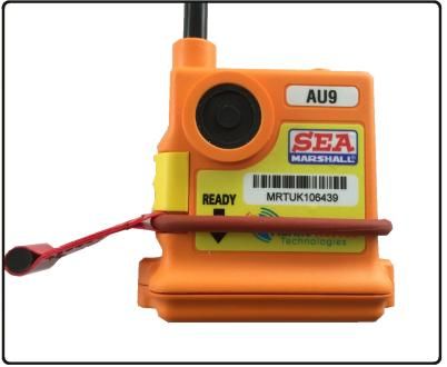
5.0 Installation of
the SARfinder®
Antenna
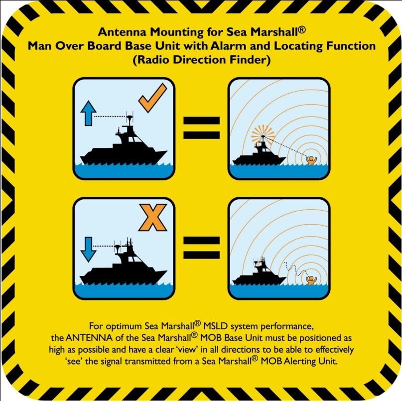
5.1 Correct antenna positioning.
The position of the antenna array is of
critical importance for the direction
finding efficiency and effective range of
the unit. The mounting position for the
antenna should be as obstacle free as
possible to avoid reflections and false
readings. The antenna should be
positioned approx 1.5m above any
other metal or antenna.
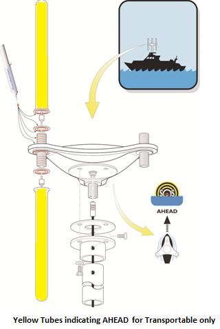
NOTE: The antenna has an ‘AHEAD →’
which must be aligned with ship’s bow
with the yellow tubes fitted also
indicating ‘AHEAD →’
The antenna should be mounted on a
suitable mast tube with an outside
diameter of 50mm, using the supplied
bracket, round silicone anti-vibration
mat, M10 fixing bolts and nylon
washers.
5.2 Assembly of the antenna
WATERPROOFING THE ANTENNA - IMPORTANT
9
Repeat application of silicon adhesive for each dipole
                                                                    Check that each dipole is sealed with no gaps

6.0 Electrical Connections
6.1 The connections between the antenna array and display unit are routed via
a 20m shielded cable. Connection to the display is internal via an IP-67 rated
connector. The power supply and relay are also terminated inside the display
enclosure via an IP-67 rated connector. To attach the power cable match up the
4 pin grey coloured power cable to the 4 pin connector on the back of the
bridge box. To attach the antenna cable align the 7 pin cable connector to the 7
pin connector on the bridge box, the other end matches to the connector on
the underside of the antenna body.

6.2 When installing the system first connect the control box to your power supply and connect all the cables in accordance
with the instructions in this manual. Activate the system to check it is working correctly. This unit will run from a 12V DC power
supply only, if your power supply is 24V DC or 120/240V AC you will need to install a step down transformer or converter
(available from MRT Ltd.).

If the power supply on your vessel is unreliable, install an isolated power supply. The manufacturer cannot be held
responsible for damage caused by wiring the unit into an incorrect power supply. Your warranty does not cover this.

6.3 WIRING FOR POWER PLUG/ UNIT POWER CONSUMPTION
NOTE: each inner cable has the number marked on.
    Pin                             Cable Description                       Cable Function
    1                               Black 1                                           Relay Contacts
    2                               Black 2                                          0V DC Negative
                                                               10
3 Black 3 12V DC Positive
4 Green/Yellow Relay Contacts
Approx POWER CONSUMPTION FOR SARfinder® 1003
ON – 120 mA
ALARMING - 1200 mA
RESET/SEARCH – 300 mA
6.4 EXTERNAL ALARM
Your unit comes supplied with a small, very loud external siren
pre-wired onto the power cable. This siren must be fitted if
you are to rely on the SARfinder®1003 to raise the alarm by
means of an audio alert. When an SOS signal is received the
circuit identifies correct characteristics of a Sea Marshall®
beacon transmission and activates the internal relay to trigger
external circuits. The audio volume is activated and the display
shows the SOS signal bearing. Press the RESET button to cancel
the external alarm and the MOB bearing will be displayed. It is
possible to connect the SARfinder to other external alarms
however this may invalidate the warranty.
117.0 HOW TO USE THE SARFINDER®1003, STEP BY STEP
Switch on - Press and hold the ON/OFF button.
↓
Press TONE DETECT (this will cancel all background noise).
↓
Select FREQUENCY (Your SARfinder®1003 is now monitoring your chosen frequency).
↓
When an SOS Signal is received the alarm will trigger.
↓
Press RESET after alarm has sounded for few seconds. This will cancel the alarms and put the SARfinder®1003 in to tracking
mode. Your unit will now display the direction of the SOS signal.
↓
Bring the vessel around so the SOS direction ORANGE LED is lit on display.
↓
Check the Received Signal Strength Indicator (RSSI) to see if the signal is near or far.
↓
Move towards SOS target checking the RSSI, when the target is very close and all four RSSI lights are illuminated.
↓
Slow the vessel down to a couple of knots.
↓
The central red RSI light will begin to flash on and off when the target is within approx. 100-200m of the vessel.
↓
Steer around the target and prepare your crew to recover the target.
↓
The RED bearing LED on the direction finding display will now move quickly around the display as the vessel moves alongside the
target.
↓
Recover the target, switch OFF the PLB and repeat as required for next target.
10.1 If for any reason you are unable to affect your rescue using the SARfinder® contact the Coast Guard and tell them you
have a man in the water wearing a 121.5MHz PLB.
11.0 BASIC Test/Checking the SARfinder system before use
1. Switch SARfinder® on, Press and hold the ON/OFF button.
2. Press TONE DETECT (to cancel background noise)
3. Select FREQUENCY (Your SARfinder® is now monitoring your chosen frequency)
NOTE: If you intend to perform a full power test you must only use a test frequency beacon of 121.65MHz. All
AU9s/PLBs (both LIVE and TEST beacons) will transmit a low power signal to approx. 30-50mtrs when in the UNARMED
position by pressing and holding the manual activation button on the front of the PLB. This can be used to test your
system. REMEMBER that the frequency on the SARfinder® will automatically revert back to the live 121.5MHz
frequency after 20 minutes.
4. Press and hold the activation button, (you are now transmitting a low power signal to a range of approx 30- 50mtrs
distance), after a few seconds the alarm will sound on the SARfinder®.
5. Leave the alarm to sound for a few seconds.
6. Press the large yellow RESET button (bottom left of display) – this will cancel the alarms and put the SARfinder® into the
tracking mode, your unit will now display the direction of the SOS signal – Keep the button on the PLB pressed down -
You should see all four RSSSI – Received Signal Strength Indicator- LEDs light up indicating the SOS signal is very close,
the RSI- Received signal indicator- will also flash to indicate close proximity to SOS target.
7. Immediately Switch Off your PLB
128.0 RECOMMNENDED SARFINDER® SEA TRIAL TEST
PROCEDURE
Each SARfinder® is taken through a series of tests before it is signed off ready for despatch: system accuracy, signal strength
check, system function check/alarm activation. These tests are performed as follows:
1. In house test on simulator to simulate different ranges and transmitted power.
2. Outside test over 0.25 mile with 100mW PLB fitted to lifejacket worn by a technician.
3. Outside test over 1 mile with 100mW PLB fitted to lifejacket worn by a technician.
4. Outside test over 2 miles with 500mW PLB fitted to lifejacket worn by a technician.
It is recommended that a “set” test and training procedure, at sea is carried out at regular intervals to familiarise crew members
with the parameters of your system.
Sea Trial Recommended Procedure
1. Make sure the PLB (Test frequency, Green case) is fitted to a lifejacket or marker buoy and a weight added so that the
lifejacket/buoy allows the antenna to be positioned at an angle of between 45 degrees to 90 degrees. This will give the
preferred angle for the beacon to transmit at optimum power. Also make sure the batteries are in good working order.
2. Switch on the SARfinder®- Press and hold the ON/OFF button.
3. Press TONE DETECT (this will cancel all background noise).
4. Select FREQUENCY to match the frequency of the test beacon.
5. Arm the PLB and throw the lifejacket overboard (the PLB will auto-activate after 2 to 5 seconds depending on the
model). Providing the PLB is fully submerged enabling the water pins make the circuit.
6. When an SOS Signal is received the MOB alarms will trigger and the LEDs on the display will flash on and off.
7. Press RESET after the alarm has sounded for few seconds, this will cancel the alarms and put the SARfinder® into
tracking mode. Your unit will now begin displaying the direction of the SOS signal, it will take a few seconds to calculate
the bearing correctly. However if you are too close the Sarfinder receiver may be swamped and a little distance may be
required.
8. Bring the vessel around so the SOS direction ORANGE LED is ahead, check the direction bearing in relation to PLB. If the
bearing is unstable press the RESET button to clear any bearing error. To completely reset the system press the TONE
DETECT button so the unit re-arms and reactivates when a SOS signal is received. Then press the RESET button to put
the unit back into tracking mode.
9. Check the Received Signal Strength Indicator (RSSI) this will tell you the approximate range of the PLB, the further away
you move from the PLB the fewer green lights will illuminate.
10. Repeat this process at ranges 0.5 mile, 1 mile, 1.5 miles, 2 miles and continue until you lose the signal. This will allow
you to determine the parameters of your system; this will vary according to placement of the antenna and weather
conditions.
11. When you are ready to affect recovery move towards the target checking the RSSI. When the target is very close all four
GREEN RSSI LEDs will be illuminated.
12. Slow the vessel down to a couple of knots.
13. The ahead bearing LED is ORANGE to indicate you are aiming straight towards the target
14. When the central RED RSI light (the head of the little red man in the middle of the SARfinder logo) begins to flash you
will be within approx. 100-200m of the target.
15. Steer around and past the target by 15° (1 bearing LED) this means you will not collide with the target in the water.
Prepare your crew for recovery of the target.
16. The target LED on the relative bearing display will now move quickly around the display as the vessel moves alongside
and past the target. Turn the vessel back around towards the target at very low speed.
17. Recover the target from the water and switch off the PLB.
13PRODUCT NAME - CREWFIX® NMEA box (Sold separately)
9.0 Overview
The CREWFIX® NMEA output allows the Sea Marshall® Base Units to automatically output the GPS position of the vessel at the
time the alarm signal is received.
9.1 Technical
The CREWFIX® is connected to the relay outputs of the monitoring system. When set in ‘tone detect’ mode and an MOB alarm is
received the internal relay closes. The Crewfix then outputs the recorded position of the vessel to a GPS plotter. 9.2 Crewfix®
NMEA 0183 Interface
Dimensions 65 x 65 x 45mm
Weight ~110g
Temperature Range -20⁰C to 70⁰C
Case rating IP55
Input signal RMC
Output signal GPWPL when MOB RS422
Software Version D1.70.
Current DrainTechnical Data - SARFinder MKIII Transportable
Contained in PVC Holdal 55 x 36 x 29mm, Total weight 12.25kg
Pelicase 29x25x18mm – Orange PVC Box
Pelicase Weight 6.85kg
Battery
Float Service: Every month, recommend inspection every battery voltage. Every three months, recommend equalization charge for one
time. Equalization charge method: Discharge: 100% rate capacity discharge.Charge: Max. current 0.3CA, constant voltage 2.35V/Cell
charge 24h. Effect of temperature on float charge voltage: -3mV/ /Cell. Length of service life will be directly affected by the number
of discharge cycles, depth of discharge, ambient temperature and charging voltage.
Antenna Base Dimensions 550 mm H x350mm W - PVC Plastic
Antenna Base Weight 950gms
Portable Antenna Pole Aluminium 35mm i/d x 45mm Depth
Antenna mounting Bracket 55mm i/d x 60mm Depth
Temperature range -20°C + 55°C (Operational)
Bandwidth 25 KHz
Modulation AM
Ports DC12V Power Cable (1m) Antenna Cable (16m)
Waterproofing IP68
Sensitivity 3 dBuV/m (threshold of target bearing resolution)
Frequencies 121.5 MHz, 121.65 MHz (Test 1), 121.775 (Test 2)
Criteria of ELT/PLB recognition Audible AM down-swept tone (compliant to ITU-R M.690-2)
Audio output max. 8Vss (speaker > 8 Ohm)
Relay contact Floating, carrying capacity max. 0.5 A/10W
Current Consumption Standby = 300mA – Tracking = 850mA – Alarming 1300 mA
If alarm + ext. speaker (8 Ohm) = 400mA
Operating Voltage 12V DC (with transient compliance to ISO 7637-2)
Antenna Gain 1.4 dBi nominal
Bearing detection method Triangular phase delta
Bearing resolution accuracy 15 @ 10 dBuv/m maximum
Antenna Triple Coax Cable Impedence: 75 Ω
o Capacitance 60pF / m
o Attenuation / 10 m: 0.28 dB @ 1.5 MHz, 2 dB @ 100 MHz, 4.7 dB @ 500 MHz
o Attenuation / 100 m: 20 dB @ 100 MHz
o Diameter: 7.2 mm x 10mtrs
o Operating temperature: –20 → +70 °C
o Coaxial Type : Triple RG179B/U
o
Standards Tested to: ETSI EN 301 489-1 V1.5.1 (2004-11)
o ETSI EN 301 489-22 V1.3.1 (2003-11)
15PRODUCT NAME - SARfinder® transportable system
10.0 Overview
The transportable versions of the SARfinder® locator units are designed to provide temporary cover for users wishing to move
from vessel to vessel. The unit has the control box display and two rechargeable batteries mounted into a waterproof peli-case.
Ideal for safety vessels moving from site to site. The operation of this system is the same as the fixed version of the
SARfinder®1003 MKIII.
10.1 Assembly of Transportable SARfinder®
10.2 Assemble the antenna in accordance with Section 2 of this booklet but do not apply any silicone sealent as you may want
to disassemble the antenna afterwards.. There are two YELLOW dipoles included with the transportable system which are to be
fitted to the ahead position of the antenna to provide a quick visual reference.
10.3 Feed the antenna cable through the antenna handle pole and connect to the underside of the antenna.
10.4 Fix the antenna handle pole to the underside of the antenna with the bolts provided.
10.5 Open the Peli-Case and connect the battery terminals (red – red, black – black). Close the Peli-Case and re-seal.
10.6 Switch on to ensure the unit is functioning and perform a quick system test as described on page 11.
The transportable SARfinder® can either be manually carried using the shoulder straps provided as shown in the photo bottom
left. Alternatively the control box (Peli-Case) can be positioned in an accessible / visible position on the boat and the antenna
held by hand or dropped into a temporary bracket as required. Always ensure the YELLOW dipoles are positioned in the AHEAD
direction (bow of boat).
IMPORTANT - If you are relying on the transportable unit for rapid response it is recommended to have the system in an
easily accessable place.
1611.0 Battery Charging SAFETY • The charger is designed for lead-acid batteries from 1,2-120Ah. Do not use the charger for any other purpose. • Use safety glasses and turn your head away when connecting or disconnecting a battery. • Battery acid is corrosive. Rinse immediately with water if acid comes into contact with skin or eyes. Seek medical advice. • Make sure that the cable is not being pinched or in contact with warm surfaces or sharp edges. • While charging, a battery can emit explosive gases, so it is important to avoid sparks in the immediate area. • Always provide for proper ventilation during charging. • Avoid covering the charger. • Make sure that the electrical cable does not come into contact with water. • Never charge a frozen battery. • Never charge a damaged battery. • Do not place the charger on the battery while charging. • The electrical connection must fulfil the national heavy current requirements. • Check the cabling in the charger before use. Make sure there are no cracks in the cabling or in the protective covering. A charger with damaged cables may not be used. • Always check that the charger has gone over to maintenance charging mode before leaving the charger unattended and connected for long periods. If the charger had not gone over to maintenance charging within 3 days, this is an indication of a problem. In this case the charger must be disconnected manually. • All batteries fail sooner or later. A battery that fails during charging is normally taken care of by the chargers advanced control, but certain uncommon errors in the battery can still arise. Don’t leave the battery charger unattended for a longer period of time. • Only mount the charger on a flat surface. • This equipment may not be used by children or by those who cannot read and understand the manual if they are not supervised by a responsible person who can guarantee that the battery charger is being used in a safe manner. Store and use the battery charger out of the reach of children. Make sure that children do not play with the battery charger. BATTERY TYPES AND SETTINGS M45 can easily be configured to charge many different types of 12V lead-acid batteries; wet batteries, MF, AGM och for most GEL-batteries. The following recommendations should, however, only be seen as guidelines. When in doubt, always consult the battery manufacturer for further instructions. The settings is made by pressing the “MODE-button” and stepping forward by pressing the button one step at a time, releasing the button when the required Mode 14.4V/0.8A mode is reached, see below. This mode is normally used for
5. Charging can be stopped at any time by disconnecting the supply cord or by setting the charger on Standby. Always remove
the power cord from the power outlet before disconnecting the battery leads from a battery.
6. If the charger lamp and the maintenance-charger lamp are flashing alternately, the reason for this is due to:
• An interruption during charging, due to a loose connection or because the battery has ceased to work.
• The battery has become sulphated. If the lamps flash for more than 30 minutes, this indicates that the battery is dead and
needs to be replaced.
• If there is an interval of more than 10 seconds between the flashes, this indicates that the battery has a high self-discharge
rate and may need to be replaced.

CHARGING PHASES
M45 operates in a four step fully automatic cycle. It begins charging with an almost constant current (0.8A or 3.6A) until
maximum voltage (14.4V or 14.7V) is reached. The charger changes mode at this point. It locks the voltage at maximum level
and allows the current to drop. The M45 switches automatically to pulse maintenance charging when the current drops to 0.4A.
                                                   The charging cycle restarts if the battery voltage drops to 12.9V.
                                                   Desulphation - Desulphation with pulsing for sulphated batteries.
                                                   Bulk - Charging where 80% of the energy is returned. The charger delivers an
                                                   almost constant current until the battery voltage reaches maximum level.
                                                   Absorption - Charging up to almost 100%. The charge current falls and the
                                                   voltage is kept constant at the maximum level.
                                                   Pulse - Maintenance phase, where the charger delivers a pulse if the battery
                                                   voltage drops. Charging varies between 95% and 100%. The battery receives a
                                                   pulse when the voltage reduces. Keep the battery in good condition when not
                                                   in use. The charger can be connected for months.

TEMPERATURE PROTECTION
M45 is protected from being overheated. The power will be reduced if the ambient temperature is raised.
MAINTENANCE
The charger is maintenance free. Note that disassembly of the charger is not permitted and will void the warranty. If the power
cord is damaged, the charger must be sent to the reseller for maintenance. The case can be cleaned with a soft damp cloth and
mild cleanser. The charger should be disconnected from the power while cleaning.
EQUIPMENT
M45 is delivered with a set of battery leads with battery pole clamps.
TECHNICAL SPECIFICATION
Model MULTI XS 3600
Voltage AC 220-240VAC, 50-60Hz
Back current drain* < 1mA
Voltage Charging Voltage Nominal: 12V
14.4V; 14.7V
Ripple** Max 50mV rms, max 0.13A
Current 0,8A; 3,6A
Ambient Temperature - 20°C to + 50°C, power is reduced automatically at increased ambient temperature.
Cooling Natural convection.
Charging cycle M45 is a multistage fully automatic charger
Type of batteries All types of 12V lead-acid batteries (Wet, MF, VRLA, AGM and GEL).
Battery Capacity 1.2–120Ah
Dimensions 165x61x38mm (L x W x H)
Insulation IP65
Weight 0.5 kg
*) Back Current Drain is what the charger uses to drain the battery if the power cord is disconnected.
**) Quality of the current and voltage are very important. High current ripple heats up the battery and makes the positive
electrode age prematurely. High voltage ripple could harm other equipment connected to the battery. M45 produces a high
quality current and voltage with very low ripple.
BULK CHARGING TIME
The table shows the length of time for bulk charging.

                                                                18
Warranty
Your unit is covered by a standard 1 year parts and labour warranty. Marine Rescue Technologies Ltd (MRT) warrants
to the purchaser that the products conform to manufacturers specifications and that the products are free of defects on
materials and workmanship for a period of one year from the date delivered to the customer/end user. In the event of a
defect, due to faulty material, design or construction, the customer will return to MRT at the business address where we,
or the manufacturer will undertake, at our choice, a repair or replacement. Warranty covers all parts, materials and
labour, provided that the product is returned to our works. Exclusions: damage caused by other than normal use and lack
of general care and attention or incorrect sealing of the unit carried out in accordance with this instruction manual. MRT
Ltd. does not accept any responsibility or any claim for direct or indirect consequences of defects of the equipment, either
during the guarantee period or at a later stage.
Repairs
MRT Ltd. offers a full and comprehensive service and repair facility with return normally within 14 days upon receipt of
customer’s authorisation.
Disclaimer
The Sea Marshall® products are an aid to recovery only, it is the responsibility of the user/operator to ensure they are fully
conversant with the operation of the equipment and the equipment is kept in full working order at all times combined with
functionality and damage checks before and after each use. MRT Ltd. does not accept liability for loss of life or injury caused
during any accident during which the equipment is being used, howsoever it arises. Sea Marshall® Alerting Units/MSLDs are
an ‘Aid to rescue only’, they do not guarantee your safety. The Sea Marshall® MSLDs will dramatically increase the chances of
detection and location of a Man Over Board. Personal safety remains at all times the sole responsibility of the individual. It is
the responsibility of the individual to inform their local Coast Guard, their senior personnel/crew members and or family of
their intended location/destination and estimated duration of journey. It is also the responsibility of the individual to notify
these people of the type of safety equipment they will be carrying. In the case of accidental activation the user should de-
activate the unit and notify the appropriate SAR Authority.
22You can also read