SOLAR PHOTOVOLTAIC DIY KIT - Installation Manual
←
→
Page content transcription
If your browser does not render page correctly, please read the page content below

SOLAR PHOTOVOLTAIC
                       DIY KIT
             Installation Manual

                                                                                   Version 1.1
                                                                   The UK Solar Panel Shop Ltd
                                              2 Pollard Garth, Skidby. East Yorkshire. HU16 5GA
                                 Tel: 01482 210089 e‐mail: technicalsupport@uksolarshop.co.uk

Note: These Instructions Should Be Read Carefully Prior
                    To Installation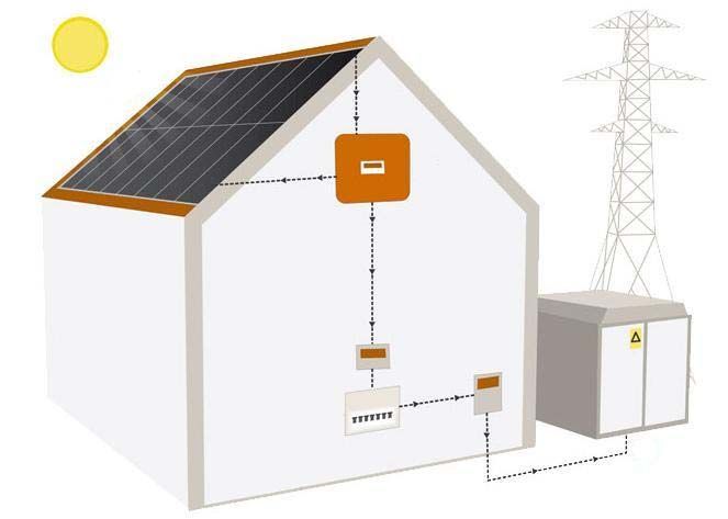
Contents

           Table of Contents:

           Introduction                                                                            ‐ Page 3
           Health & Safety                                                                         ‐ Page 3
           Kit Check sheet                                                                         ‐ Page 3
           MCS Accreditation                                                                       ‐ Page 3

           Installation                                                                            ‐ Page 4
           PV Module Layout                                                                        ‐ Page 4
           Rafter Identification                                                                   ‐ Page 5
           Roof Hook Installation                                                                  ‐ Page 6
           Rail Installation                                                                       ‐ Page 8
           PV Module Installation                                                                  ‐ Page 9
           Inverter – Board 1                                                                      ‐ Page 11
           AC Isolator & OFGEM Meter – Board 2                                                     ‐ Page 11
           Cabling                                                                                 ‐ Page 11

           Appendix                                                                                ‐ Page 12
           Appendix 1                                                                              ‐ Page 12
           Appendix 2                                                                              ‐ Page 13
           Appendix 3                                                                              ‐ Page 14
           Appendix 4                                                                              ‐ Page 15

                                    Note: All instructions and data values within this document are based      Page | 2
                                     on our standard DIY KITS; if your kit has alternative components the
                                                    details in this manual may not be valid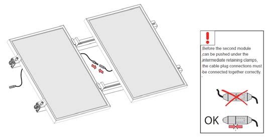
Introduction
Introduction
This installation manual contains essential information for the effective and safe installation of your solar
photovoltaic (PV) kit. It is essential that this kit is fitted by a competent person with relevant experience, if this kit
is installed without the required knowledge base your installation may not be eligible for MCS accreditation and
any guarantees may be void.
This technical documentation should be available with you at all times during the installation, but prior to
installation please read these instructions as in many cases it will prevent problems from occurring during the
installation process.
In all cases any technical advice you require can be obtained by contacting us via;
tel: 01482 210089
e‐mail: technicalsupport@uksolarshop.co.uk
Health & Safety
From the outset, the designer and installer of a PV system must consider the potential hazards carefully, and
systematically devise methods to minimize the risks.
The main safety issues are:
The supply form PV modules cannot be switched off, so special precautions should be made to ensure
that live parts are either not accessible or cannot be touched during installation, use and maintenance.
PV systems include d.c wiring, with which few electricians are familiar so DON’T attempt to alter or
terminate any connections.
The installation of PV systems presents a unique combination of hazards – due to risk of electric shock,
falling and simultaneous manual handling difficulty. All of these hazards are rarely encountered all at
once. While roofers may be accustomed to minimizing risks of falling or injuries due to manual handling,
they are not used to dealing with the risk of electric shock. Similarly, electricians would be familiar with
electric shock hazards but not with handling large objects at heights.
There are other hazards/risks that are specific to the installation location that MUST be considered and minimized
before the installation can commence.
ANY PV system installation MUST comply with Health & Safety Requirements: BS7671 and other relevant
standards and Codes of Practice, before any works can commence.
Kit Check sheet
Please ensure all equipment has been delivered, and no parts are damaged.
Please complete the PV Modules check sheet (APPENDIX 1)
MCS Accreditation
In order for your installation to receive MCS accreditation and therefore the Feed‐in Tariff scheme (FITs) you must
follow this instruction manual closely. The UK Solar Panel Shop Ltd will only apply for/issue the MCS accreditation
once all aspects of the installation are carried out satisfactorily
Page | 3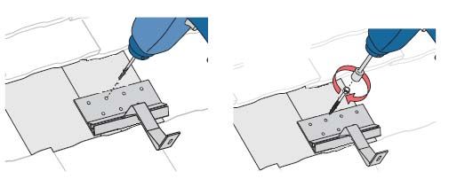
Installation
Installation
There are still a few steps that need to be carried out before any installation works can begin.
Ensure that all required access platforms/scaffolding are erected and certified.
All relevant Personal Protective Equipment (PPE) is on site and is worn at all times. For more details on
required PPE refer to : Personal Protective Equipment at Work Regulations 1992
Wear protective gloves Section off the site and secure
against falling objects
Wear a safety helmet
110V Tools Only
Ensure that you have
access to a first aid kit
Ensure manual handling route/mechanical equipment for lifting the PV modules to the roof is safe and
adequate.
PV Module Layout
At this point you will have a clear idea of the module arrangement you wish to achieve, whether it be a simple
2kWp system in portrait orientation or a far more complicated layout where you are trying to navigate around roof
lights. Before you start trying to lift tiles and fit brackets, it is vital that the roof space is measured once again to
ensure the layout fits. Please refer to PV array dimensions below;
System Size (kWp) Orientation Total Dimensions (wxhxd:mm)
2 Portrait 4028x3296x40*
3 Portrait 6032x3296x40*
4 Portrait 8036x3296x40*
2 Landscape 6612x2024x40*
3 Landscape 6612x3026x40*
4 Landscape 6612x4028x40*
*‐ inclusive of all clamps
Figures based on Canadian Solar CS6P – 250P PV Panel. Alternative panels may alter dimensions.
Page | 4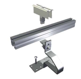
Installation
Rafter Identification
Once you are satisfied the array will fit on your roof, the next step is to determine the rafter locations. To calculate
their position you will need to locate the end most rafter within your array. To do this, first remove the tiles in the
approximate area (fig.1) of this rafter until you can see/feel the rafter (if membrane is present). Once the first
rafter is located you can then find the approximate location of all the others you require by simply measuring
across the tiles to the approximate area (determined by rafter distance measured from within the roof space) and
repeating the previous step.
Guide diagrams:
b
½L
L = PV Module Length
a = min. distance to roof edge (min 300mm)
b = max. spacing between brackets
Fig 1
a
In all cases, values a & b should be calculated in the design stage, factors to determine values;
Roof Structure
Rail gauge & rail cantilever calculation (APPENDIX 2)
Local weather factors (wind/snow) (Appendix x)
Page | 5Installation
Roof Hook Installation
Ensure all roof hook positions are correct. Once you have allocated all positions the roof hooks can be mounted to
the rafters.
Note: Packers may be required (Page 7 – Fig 4) between rafter and roof bracket to achieve (Page 6 – Fig 3)
Follow Diagrams
Fig 3
Drill pilot holes with 4mm drill bit Install 2 x [M8x50mm] screws (provided)
Page | 6Installation
Fig 4
NOTE: It may be necessary to grind away some portions of the tiles to allow bracket to seat correctly (Fig 4)
Page | 7Installation
Rail Installation
Orientation – Portrait
Ensure all brackets are in correct position and fixed securely. The rails can now be attached to the brackets,
ensuring cantilever calculations have been completed (APPENDIX 2)
The rails simply click onto the utilizing the Schletter Rapid+2 Roof Hook System, this allows the rail to simply click
into position and then be tightened into position. NOTE: Ensure the rail is in aligned before clicking in as there is
very little lateral movement once clicked into position.
Schletter Rapid+2 System Click rail onto Klick‐top Tighten screw to fix rail into position
If the rail requires jointing, simply slide the jointer/clamp into position bridging the two rails and tighten the nuts
provided.
Once you have installed the rails it is imperative that you carry out the measurements below to ensure they are
square to each other.
Page | 8Installation
PV Module Installation
Installing the PV modules onto the rail is an area that many find difficult. However it is relatively simple, the MOST
important aspects are as follows and if you follow these simple steps you will find the process straight forward;
Ensure the rails are square (Refer to Page 8)
Ensure you have installed the DC cable to the DC isolator (APPENDIX 4)
Measure your overall array width including Mid & End Clamps
(Array Width = 20mm + [No. Modules x (Module Width + 20mm)])
Measure your rail length
Calculate the spacing before first End Clamp: 131001‐40 (Rail Length – Array Width)
2
st
Place the 1 PV Module on the rail, ensure its square to the rails as if NOT it WILL affect all further
modules (Refer to Appendix 2) for positioning)
Fix the Module to the rails using the Module End‐Clamps.
Push into rail but do NOT screw down Module Mid‐Clamps on the
adjacent side of the module (Fig 2)
Repeat the process using Mid‐Clamps until you install the last module and then install 2x End‐clamp,
connecting the DC cable as shown
Page | 9Installation
Fig 2 – Diagram shows a simple design with clamp locations
Page | 10Installation
Example Purpose ONLY
Inverter – Board 1
The installation of the inverter is straight forward. The UK Solar Panel Shop provides an inverter board (Board 1)
with all ancillaries necessary. This board can be mounted in most locations but we recommend your loft space, as
the inverter does require ventilation and easy access to the array for cabling solutions, certain inverters can also
emit a low level noise during high generation (refer to manufacturers details for dB levels). Dependant on which
inverter you have requested or been supplied, the exact location regulations will differ. However we will always
issue you with the relevant inverter installation guide for your assistance.
The board that you will receive in your kit can be simply mounted to a wall within the loft space (fixings supplied).
AC Isolator & OFGEM Meter – Board 2
The installation of AC Isolator & OFGEM Meter board (Board 2) is again provided by The UK Solar Panel Shop all
that you as the customer have to do is mount it, the kit as standard would require board 2 to be mounted next to
your current distribution board & REC Incoming Supply (fixings supplied).
Cabling
The kit you have received will have all the cabling you require for your installation, as standard the kits come with;
2x 10m DC – 4.0sqmm LSOH Black 0.6/1KV (MC4 pre‐terminated)
and either;
20m External SWA 3‐Core 6943X*
20m Internal PVC/PVC Twin/Earth 6242Y* *‐ Cable Cross Sectional Area dependant on installation
This cabling should be installed as shown in APPENDIX 4
CABLE ROUTING SHOULD BE CARRIED OUT BY A COMPETANT PERSON ADHERING TO ALL REGULATIONS IN BS7671
Page | 11Appendix
Appendix 1
Please complete the table below for your own records as you may need to refer to them in the future.
PV Modules
Make Model Serial Number
Inverter
Make Model Serial Number
OFGEM Generation Meter
Make Model Serial Number
Page | 12Appendix
Appendix 2
Ensure you rail cantilever does not exceed the range stated below:
¼L
½L
L
¼L
L = module length c = maximum cantilever
a = module width c ≤ 40% of X (max 400mm)
Bp = mounting rail length
X = fixing intervals
Example:
X = 900mm
therefore the maximum cantilever can be;
max c = (900x0.4) 360mm
Page | 13Appendix
Appendix 3
There are various factors that determine the distance between roof hooks (value X – Appendix 2);
Rafter location and distance apart
Wind loading for your area
Snow loading for your area
Page | 14Appendix
2x 10m DC – 4.0sqmm LSOH Black 0.6/1KV External 4.0sqmm SWA 3‐Core 6943X
(MC4 pre‐terminated) OR
Internal 4.0sqmm PVC/PVC Twin/Earth
6242Y
Appendix 4
Page | 15You can also read