Spectroscopic Coronal Observations during the Total Solar Eclipse of 11 July 2010
←
→
Page content transcription
If your browser does not render page correctly, please read the page content below
Spectroscopic Coronal Observations during the
Total Solar Eclipse of 11 July 2010
A.G. Voulgaris • P.S. Gaintatzis • J.H. Seiradakis • J.M. Pasachoff • T.E. Economou
A.G. Voulgaris
Evrivias 5c, GR-542 50 Thessaloniki, Greece
P.S. Gaintatzis, J.H. Seiradakis ()
Department of Physics, Section of Astrophysics, Astronomy and Mechanics, Aristotle University
of Thessaloniki, GR-541 24 Thessaloniki, Greece
e-mail: jhs@astro.auth.gr
J.M. Pasachoff ()
Williams College—Hopkins Observatory, Williamstown, Massachusetts 01267, USA
e-mail: eclipse@williams.edu
T.E. Economou
Laboratory for Astrophysics and Space Research, Enrico Fermi Institute, University of Chicago,
Chicago, IL 60637, USA
Abstract The flash spectra of the solar chromosphere and corona were measured with a slitless
spectrograph before, after, and during the totality of the solar eclipse of 11 July 2010, at Easter Island,
Chile. This eclipse took place at the beginning of the Solar Cycle 24, after an extended minimum of solar
activity. The spectra taken during the eclipse show a different intensity ratio of the red and green coronal
lines compared with those taken during the total solar eclipse of 1 August 2008, which took place toward
the end of Solar Cycle 23. The characteristic coronal emission line of forbidden Fe XIV (5303 Å) was
observed on the east and west solar limbs in four areas relatively symmetrically located with respect to
the solar rotation axis. Subtraction of the continuum flash-spectrum background led to the identification
of several extremely weak emission lines, including forbidden Ca XV (5694 Å), which is normally
detected only in regions of very high excitation, e.g., during flares or above large sunspots. The height of
the chromosphere was measured spectrophotometrically, using spectral lines from light elements and
compared with the equivalent height of the lower chromosphere measured using spectral lines from heavy
elements.
Keywords Eclipses • Corona • Chromosphere’s Height • Continuum Background • Ionized Iron • Lower
Chromosphere • Continuum Subtraction
1 Introduction
We continue our joint work on the solar chromosphere and corona, which started with the
total solar eclipse of 29 March 2006 (Voulgaris et al., 2010). On 11 July 2010, we observed the
total solar eclipse at Easter Island in the South Pacific. The flash spectrum of the solar corona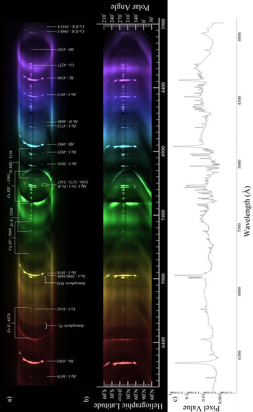
A. G. Voulgaris et al.

was measured with a slitless solar spectrograph made by one of us (AV). Although Solar Cycle
24 had just begun, the emission lines from forbidden both Fe X and Fe XIV were clearly visible in
the coronal spectra, whereas only the cooler of the two lines were detectable during solar
minimum. This change in ratio indicates an increase in the temperature of the corona as solar
activity is on its way to the next solar maximum, perhaps the last solar-activity cycle for some
decades (Pasachoff, 2011; Pasachoff and MacRobert, 2011).
        Throughout the recent solar minimum, the total absence of energetic flares as well as the
general low solar activity resulted in a drop of the corona temperature. During that time,
significant changes were observed in the intensities of the forbidden Fe X and Fe XIV emission
lines, corresponding to ionization temperatures of 1.2×10⁶ K and 1.8×10⁶ Κ, respectively. Other
strong lines are available in the infrared, as discussed by Pasachoff, Sandford, and Keller (1978)
and, with improved techniques, by Habbal et al. (2011). During the solar minimum, many known
multiply ionized coronal emission lines are not detectable, since they require a much higher
temperature. An example of such elements is forbidden Ca XV (5694 Å), with an ionization
temperature of 2.3×10⁶ K, whose emission lines have never been reported during solar minimum.
See also Wagner and House (1968).
        Studies of the total solar eclipses from the ground are part of an effort to understand the
processes that are going on in the solar corona with ever improving ground equipment (Singh et
al., 2011) and supplementing the results obtained from space missions (Pasachoff, 2009a,
2009b).
        From the work of Mazzotta et al. (1998), it can be concluded that the multiply ionized
elements with high ionization potential continue to emit even at lower temperatures, albeit with
extremely low signal, near or at the limits of the continuum. This extremely faint signal from the
above-mentioned elements explains why such lines are not directly observed during the solar
minimum. Faint emission lines are barely detected in the spectra.
        In this article, we concentrate on the analysis of flash spectra that were obtained during
the 2010 total solar eclipse and the possibility of detecting extremely low intensity emission lines
from multiply ionized elements in the solar corona. These extremely faint emission lines are
easily recognized, since they follow the circular solar limb pattern, similar to the stronger
emission lines.

2. Observations and Data Recording

2.1. The Total Solar Eclipse of 11 July 2010, at Easter Island

           We observed the total solar eclipse from Easter Island, Chile, South Pacific (longitude
     ο
–109 25΄ 29.2΄΄ and latitude –27o 08΄ 36.3΄΄) under exceptionally clear weather conditions, in
spite of the general weather variability of the previous days and rain until the very last morning
of the day of the eclipse. The observations took place at the premises of the Vai Moana Hotel, 2

                                                 2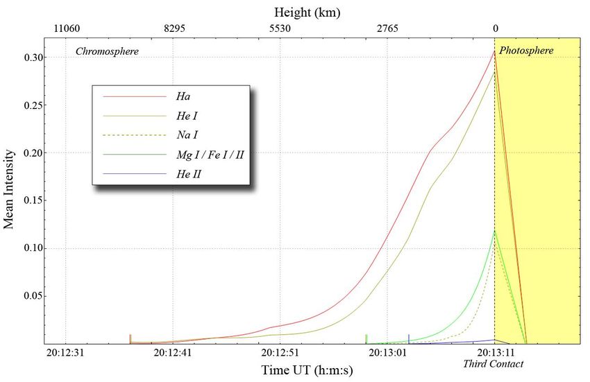
Spectroscopic Coronal Observations during the Total Solar Eclipse

                                                                      Km from Hangaroa, the capital of
                                                                      the island. The observing site was
                                                                      26.6 km away from the central
                                                                      line of the eclipse. The duration of
                                                                      the total eclipse at our site,
                                                                      uncorrected by the limb profile,
                                                                      was 4 minutes and 41.5 seconds;
                                                                      the Kaguya-LRO derived profile
                                                                      gave a duration of 4 minutes and
                                                                      35.4 seconds. The middle of
                                                                      totality occurred at 20:10:49.8 UT
                                                                      (Espenak and Anderson, 2008;
                                                                      Jubier, 2010) with local time = UT
                                                                      –6 h, or 14:10. As is typical near
                                                                      solar minimum, the corona was
                                                                      extended equatorially without
                                                                      high-latitude streamers and with
                                                                      only plumes showing near the
                                                                      poles (Figure 1). The corona’s
Figure 1 The inner and middle corona of the total solar eclipse of 11 structure in Figure 1 was
July 2010. Twenty-five images, of several exposure times, have been   enhanced       using     previously
composed using a phase-correlation method. In the composed image,     published digital techniques of
local adaptive filters have been applied for the enhancement of       Druckmüller       (2006,     2009).
corona's structure. North is up.                                      Pasachoff et al. (2011a) provide
                                                                      extensive coverage of coronal
 imaging of this eclipse from the same site on Easter Island, from Tatakoto in French Polynesia,
 and from several solar spacecraft. The solar-activity cycle had risen considerably since the
 China/Marshall-Islands observations of the 22 July 2009 total solar eclipse, for which the
 sunspot number was essentially zero (Pasachoff et al., 2011b).

2.2. The Slitless Spectrograph and
     Data Recording

        A Canon 40D digital camera
and a slitless spectrograph that have
been described by Voulgaris et al.
(2010) were used to record the flash
spectrum. We used ISO 400 with
exposure time 1/8000 second during
the partial eclipse, between 1/5000
second and 1/1000 second, a few
seconds before the second and after
the third contact and between 1/50
second and 1/25 second during the
total phase. The flash spectrum was          Figure 2 The dispersion of the spectrograph as a function of
captured before, during, and after the       wavelength.

                                                    3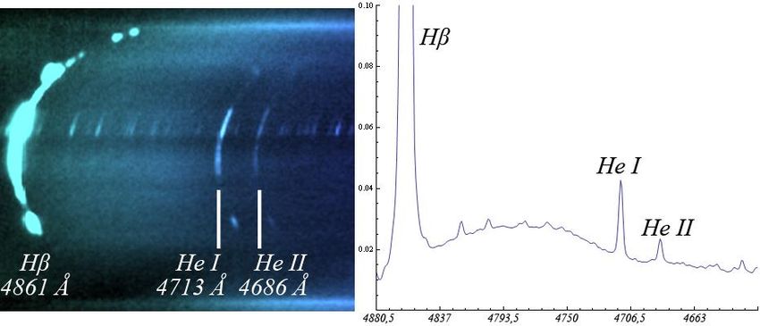
A. G. Voulgaris et al.

total eclipse in 179 images. In each image, the entire solar disk corresponded to 275 pixels or
5065 km pixel–1. We show the dispersion of the spectrograph as a function of wavelength in
Figure 2.

3. Data Analysis and Image Processing

        During totality, the Moon completely covers the photosphere and light comes only from
the chromosphere and the solar corona. Light from the corona derives mainly from three sources:
The continuum (Κ), the emission (Ε), and the Fraunhofer (F) coronas (i.e., Golub and Pasachoff,
2010) and references in Pasachoff (2010). A number of telluric absorption lines are generated in
Earth’s atmosphere (mainly from O2 and H2O), whose intensities depend on the thickness of the
atmosphere and on the terrestrial water vapor content. These lines are detectable in bands at the
yellow (H2O absorption, 5875.6 Å – 5990.9 Å), orange (O2 absorption, 6276.6 Å – 6310.6 Å,
band-a), red (H2O absorption, 6472.4 Å – 6586.6 Å), and near infrared (O2 absorption, 6867.1 Å
– 6924.1 Å, band-B) part of the spectrum (Buil, 2011).
        During totality, the flash spectrum is dominated by light from the K- and the E-corona.
The E-corona in visible light is dominated by strong emission lines of forbidden Fe XIV (green),
forbidden Fe X (red), and several other weak lines, which are difficult to detect as they are
overwhelmed by strong continuum (K). The continuum background (K-corona) originates from
scattered photospheric light and does not give any significant information of the energy content
of the solar corona. So, we applied a set of techniques that resulted in significant reduction of the
background continuum. Firstly, we combined a large number of images in order to increase the
signal-to-noise ratio. Then the continuum was subtracted from this composite image, resulting in
a clear view of the E-corona and the chromospheric emission lines. Finally, the emission lines
were enhanced with a linear transfer function. In Figures 3 and 5 we assume that the flash
spectrum extends along the horizontal axis (x). The range of pixel values in all gray images is
normalized to double precision real numbers (64-bit) between 0 (black) and 1 (white).
        Before proceeding with the analysis, we applied two corrections to the data.

    (i) Because the dispersion of the spectrograph (Å pixel–1) is not a linear function of the
         wavelength (Figure 2), the spectra were linearized with respect to wavelength.
    (ii) Because we used a slitless spectrograph, all spectral lines follow the circular shape of the
         chromosphere. Furthermore, this circular shape is distorted to elliptical shapes of varying
         semimajor x-axes, as we move away from the optical axis of the spectrograph.

The relevant corrections were made using Wolfram’s Mathematica v.8.0 by one of us (P.G.). The
procedure used to make the above corrections is described in Section 3.3.

3.1. Alignment

       In order to produce a final composed spectrum at third contact (Figure 3a) the available
images (15 in total) had to be (i) aligned and (ii) added taking into account the exposure time of
each image (Equation (2)). The alignment was achieved using the phase-correlation method (De
Castro and C. Morandi, 1987; Reddy and Chatterji, 1996; Druckmüller, 2009). In particular, for

                                                  4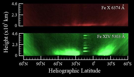
Spectroscopic Coronal Observations during the Total Solar Eclipse
the calculation of the translation (Δx, Δy) of an image A(x,y) to an image B(x,y) the following
expression was used:
1 F Axy F Bxy u v
2 2
x, y arg max F exp 2
, (1)
F Axy F Bxy
x, y
2
uv xy
where F is the Fourier transform, F-1 is the inverse Fourier transform, ε is a sufficiently small
non-zero real number, and σ is the standard deviation of a Gaussian function. The quantities (x,y)
are the spatial coordinates and (u, v) are the corresponding frequency coordinates. For the
parameters ε and σ we used the values ε = 0.0005 and σ = 2. Using the above transformation, the
15 images of the flash spectrum that had been captured in the time interval (t3rd – 45sec, t3rd)
(where t3rd is the instant of third contact) were aligned, with respect to the solar corona. Then, the
aligned images were averaged:
Pi x, y
n
1
I x, y , (2)
n i 1 ti
where ti is the exposure time of image Pi(x,y) and n = 15 is the total number of images to be
combined. The composed image I(x,y) is presented in Figure 3a, while a cut across the y-axis
(white line on either side of Figure 3a) is presented in Figure 4a.
3.2. Continuum Estimation and Subtraction
The continuum background intensity is not smooth along the y-axis; however, it extends
smoothly along the x-axis, a fact that allows us to estimate it. Then, we can subtract it from the
composed image I(x,y). The continuum background can be estimated by applying a sequence of
digital filters as presented below.
Firstly, we calculate the image Ar(x,y):
Ar x, y min I z, y : z x r , x r , (3)
where r is twice the maximum base width (in pixels) of the strongest emission lines in Figure 3a.
This was found to be r = 50 pixels. Then, by using the convolution operator, we smooth the
image Ar(x,y) along the x-axis and we estimate the continuum background Ic(x,y):
xmax
I c x, y Ar x, y G x Ar t , y G x t dt , (4)
0
where G(x) is the Gaussian function with σ = 50 pixels. The image Ic(x,y) is a very good
approximation of the continuum background spectrum (Figure 3b and 4b). Finally, the difference
I E x, y I x, y I c x, y (5)
5A. G. Voulgaris et al.
6
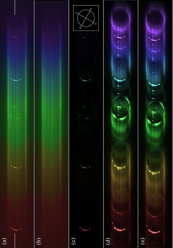
Figure 3 From top to bottom: a) Composed image I(x,y). b) Continuum background Ic(x,y). The North -- South axis in all images is rotated by 29.5o clockwise
with respect to the vertical axis.c) E-corona IE(x,y). d) E-corona IE(x,y) linearly enhanced. e) Linearization of the enhanced image with respect to wavelength T1
Ic(x,y). In this spectrum the resolution (Å pixel–1) along the x-axis is constant.Spectroscopic Coronal Observations during the Total Solar Eclipse
is the spectrum of the E-corona (Figure 3c, Figure 4c). In order to enhance the details of the
displayed spectrum of the E-corona, a suitable linear transfer function was applied to the image
IΕ(x,y) (Figures 3d and 4d).
Figure 4 a) Top left: the cut across the y-axis of Figure 3a. b) Top right: the cut across the y-axis of Figure 3b
at the same y-location as the white line either side of Figure 3a. c) Bottom left: the cut across the y-axis of image
IE(x,y) at the same y-location as the white line either side of Figure 3a. d) Bottom right: the cut across the y-axis
of Figure 3d at the same y-location as the white line either side of Figure 3a.
3.3. Linearization of the Spectrum
It is obvious from Figure 2 that the dispersion (Å pixel–1) of the spectrograph depends on
the wavelength. This means that in order to proceed with the identification of emission lines we
have to linearize our spectra. Let w be the width of IΕ(x,y) and λmin (λmax) the smallest (largest)
recorded wavelength in the right (left) limit of IΕ(x,y). Let us define a cut (x,y0) at an arbitrary
height y0 across the spectrum and let λ(x) be the corresponding wavelength along the cut. Figure
2 shows exactly the absolute derivative of λ(x) as a function of wavelength. The function
λ: [0,w] → [λmin,λmax] of IΕ(x,y) is strictly monotonic and can be estimated by fitting a smooth
curve on the points (xi, λi) of emission lines of the flash spectrum that are easily recognized (e.g.
H, He, Na, Mg, Ca II) of the flash spectrum. For our purpose, we used a fourth-order polynomial.
The linearization of the spectra was achieved via the transformation
x max
T1 x, y w , y, (6)
min max
7A. G. Voulgaris et al.
8
Figure 5 From top to bottom: a) Image T2T1IE(x,y) linearly enhanced. b) Linearization with respect to circumference of the solar disk T3T2T1IE(x,y) linearly enhanced.
c) f(λ) with υ1 = 270ο and υ2 = 280ο .Spectroscopic Coronal Observations during the Total Solar Eclipse
where each pixel at position (x,y) of the spectrum IΕ(x,y) is mapped to the position T1(x,y) of the
new spectral domain T1IE(x,y) (Figure 3e).
We notice that each circumference of the solar disk in the linearized domain (Figure 3e),
as a function of wavelength, in the flash spectrum T1IE(x,y), is approached by an ellipse, with
minor axis [2b] parallel to the y-axis and major axis [2a] passing through the centers (x΄, y0) of
the solar images in the spectra. This means that the linear transformation T2(x,y) = (x, ay/b),
where each pixel at the position (x,y) of the spectrum T1IE(x,y) is mapped to the position T2(x,y)
of the new spectral domain T2T1IE(x,y), transforms the ellipses to circles of radius a (Figure 5a).
Each pixel at position (x,y) of the spectral image T2T1IE(x,y) lies on a western semicircle
of radius a centered at a point (x΄, y0). If θ is the polar angle of this pixel, then x = a cosθ + x΄ and
y = a sinθ + y0. For the linearization of the western semicircumference we used the
transformation
T3 x, y x a a cos , y0 a a (7)
where each pixel at position (x,y) of the image T2T1IE(x,y) is mapped to the position T3(x,y) of the
new image T3T2T1IE(x,y) (Figure 5b). In image T3T2T1IE(x,y) the horizontal x-axis is proportional
to the wavelength and the vertical y-axis is proportional to the polar angle. Finally, the function
2
1
f T3T2T1I E , d (8)
1
is the integrated intensity of the emission lines along the circumference of the solar images in the
interval of polar angles [υ1, υ2]=[270ο, 280ο] (Figure 5d).
4. The Emission Spectrum of the Solar Chromosphere and Corona
4.1. Emission Lines of the Solar Chromosphere
The chromospheric emission lines Ηα, Ηβ, Ηγ, Ηδ, He I (D3), Ca II H and K (Pasachoff
and Suer, 2009; Voulgaris et al., 2010) as well as the emission lines of the heavier elements of
the lower chromosphere of Mg I, Fe I / ΙΙ, Na I (D1, 2) were visible just a few seconds after second
contact and a few seconds before third contact (namely, after the photosphere was completely
covered by the Moon) (Figure 5a). At the same time, on the eastern and western limbs,
prominences in the emission lines from Η Ι (Balmer series), He I, and from Mg I were also
detected.
4.2. Emission Lines of the Solar Corona
Besides the chromospheric emission lines, the two basic coronal forbidden lines Fe X
(6374 Å – ionization potential 235 eV) and Fe XIV (5303 Å – 355 eV) (Jefferies et al., 1970;
Gibson, 1973) were readily seen. In order to investigate the spatial distribution of the above lines
we have magnified and rearranged part of Figure 5b (see Figure 6). It is obvious that Fe XIV
emits at two separate medium heliographic latitudes (6o – 36o N and 24o – 66o S from the solar
9A. G. Voulgaris et al.
Equator) and at extended heights above the chromosphere, where the temperature is higher,
while there is no emission in the equatorial area (24o S – 6o N). On the contrary, Fe X emission is
relatively homogeneous and covers an extended area along the chromosphere and its distribution
occurs at low heights, where the temperature is lower. The regions covered by the two emission
lines do not coincide. At this point, it should be mentioned that during the 29 March 2006
eclipse, which occurred well past the
solar maximum, the distribution of
forbidden Fe XIV was much closer to
the solar Equator (– 20o to +15o)
(Voulgaris et al., 2010).
At the beginning of a new
solar cycle, the butterfly diagram
records the appearance and the
evolution of sunspots in medium
heliographic latitudes (≈15o to ≈40o)
above (or below) the solar Equator.
On the other hand, during the end of
Figure 6 Comparison of the two principal coronal emission lines, the solar cycle sunspots appear close
forbidden Fe X and forbidden Fe XIV, in the western limb area. to the solar Equator [≤ |10 o|]. Thus it
seems that the heliographic
distribution of Fe XIV probably follows a similar butterfly diagram. This correlation is expected
as the region immediately above sunspots exhibits high activity (eruptive prominences, flares,
etc.), associated with higher temperatures.
After a thorough mathematical analysis, the weak forbidden coronal lines Ni XIII (5115.8
Å – 350 eV – Tionization = (1.2 – 2.8)×106 K), Ar X (5539.1 Å – 423 eV – Tionization = (0.35–
3.0)×106 K)) and the extremely weak line Ca XV (5694 Å – 820 eV – Tionization = (2.2 – 7.0)×106
K)) (Jefferies et al., 1970; Gibson 1973; Mazzotta et al., 1998) became visible (Figure 5a).
Forbidden Ca XV emission needs the exceptionally high coronal temperatures that
often occur during solar maximum and, in particular, in energetic regions, such as coronal
regions above solar flares. However, according to the work of Mazzotta et al. (1998), emission
from multiple ionized elements (such as forbidden Ca XV) can happen even at lower
temperatures, albeit with an extremely low intensity, which makes the detection of the emission
line very difficult.
During the analysis and after the subtraction of the continuum background from the
composite flash spectrum, a faint forbidden emission line of Ca XV (5694 Å) was observed
(Figure 5a). Despite the fact that this line is extremely weak (200 times fainter than the Fe XIV
line, Figure 5c), it follows the circular solar limb pattern, similar to the stronger emission lines.
As can be readily seen from the width of the line, the spatial distribution of [Ca XV] (5694 Å) is
extended, signifying that the contribution originates from a wide coronal area covering a large
range of heights on the solar corona.
As mentioned in the previous paragraph, the forbidden Ca XV (5694 Å) emission line
has been detected previously. However, the forbidden Ca XV (5446 Å) line was not detected in
our data. This line is known to be very weak. Its ratio (Ι5694Å /Ι5446Å) is not constant, varying
between 1.67 and 3.13 (Chevalier and Lambert, 1970). During the total solar eclipse of 30 May
10Spectroscopic Coronal Observations during the Total Solar Eclipse
1965, the 5694 Å line was detected, but the 5446 Å line was undetectable (Curtis, Dunn, and
Orrall, 1965). Furthermore, according to BASS2000 (see also Kubát et al., 2010) any telluric
absorption lines that could exist in the spectral band around the forbidden Ca XV emission line
should be extremely weak, well below the sensitivity of our instrument.
4.3. The Height of the Chromosphere Deduced from the Mg I, Fe I / II, Na Ι, Ηα and He I (D3)
Emission Lines
The emission lines of the light
elements H and He were visible many
seconds after the second contact and
before the third contact (see also
Voulgaris et al., 2010). This persistence
reflects the fact that these elements are
distributed over large heights above the
photosphere. This is corroborated by the
visibility of prominences at large heights
during the middle of totality. On the
contrary, the emission lines of the
elements heavier than He, such as Fe,
Mg and Na, became visible very briefly
(a few seconds only) after the second
contact (and before the third contact),
because these elements are distributed
only in lower heights. It should be noted
that during the middle of the eclipse of
11 July 2010, no emission lines of these
elements were observed, because the
region where they are formed was
entirely covered by the lunar disk. The
ratio of the angular diameter of the
Moon to the angular diameter of the Sun
was 1.05646 (Espenak and Anderson,
2008; Jubier, 2010). This relatively large
diameter means that during totality, the Figure 7 a) Top: Second (C2) and third (C3) contacts with
Moon was covering a large portion of respect to the plane of the Moon's orbit. The orientation of the
the Sun’s atmosphere well above the system agrees with Figures 3 and 5. b) Bottom: Calculation of
photosphere. During the middle of height h of the chromosphere as a function of length r. The
totality, the Moon was covering an extra segment r is parallel to the moon's orbit.
39290 km above the eastern and western limbs. This extra coverage during the totality is
sufficient to completely cover the chromosphere.
At our observing location at Easter Island, we were 26.6 km off the center line of the total
solar eclipse, so the eclipse was not central from our observing place. During totality, the
projected movement of the center of the Moon (M1M0M2), with respect to the center of the Sun
(S), was in a straight line at constant speed. According to Jubier (2010), the angle M1SC3 is φ =
13.25ο (Figure 7a) and the point of the third contact took place at the polar angle 275°. (With a
11A. G. Voulgaris et al.
smooth lunar limb profile, C3 would be at 282°, but because of a lunar valley located roughly
between 270° and 280°, the real C3 is shifted).
During totality the integrated intensity [ĨE(λ, t)] of the distinct emission lines of each
chromospheric element, in a suitable region [λ – Δλ/2, λ + Δλ/2] × [υ1, υ2] was measured as a
function of time, t. Δλ was chosen to be twice the width of the Hα line (50 Å). The calculation of
the integrated intensity was performed by the relation
/2
I E , t
/2
ft d (9)
where ft(λ) is the function of the integrated intensity of emission lines along the circumference of
the images of the solar disk, (eq. 8), from polar angle υ1 = 270ο to υ2 = 280ο, as a function of
time t. In this interval of polar angles, no prominences were present. The integrated intensity
[ĨE(λ, t)] is directly proportional (for suitably small Δυ) to the customary integrated intensity
[Ε(λ, t)] that was introduced by Cillié and Menzel (1935) and used by Dunn (1968):
1/2
E , t x, y, z e dx dy dz (10)
h t 1/2
where ελ(x, y, z) is the volume emission coefficient at a point in the chromosphere and τλ is the
optical depth measured along the line of sight from that point to the observer. The rectangular
coordinate system is shown in Figure 7a (the z-axis is normal to the xy-plane toward the
observer) and h(t) is the height of the Moon's limb above the photosphere (transit). When h = 0,
the intensity of the emission lines of all elements reaches its maximum value. This maximum
occurs at second and third contacts (Voulgaris et al., 2010). We define the maximum height that
each element [i] reaches, as the height [hi,max] above the photosphere where the emission falls
below our detection limit (Figure 8). If the eclipse is central, the two contacts points [C2 and C3]
are diametrically opposite and the Moon’s motion is perpendicular to the tangent of the solar
disk at the contact points along the height h of the chromosphere. Since our observing site was
not directly on the central line, the direction of the motion of the Moon [r] was at an angle υ =
13.25ο with respect to the height [h] above the contact points (Figure 7b). We can easily calculate
the length r for any element, through the relation r = vΔt, where Δt is the length of time during
which the emission line of the element was detectable, and v is the velocity of projected cover of
the solar disk by the Moon. In our case, v was 285 km s–1 (Jubier, 2010). The height [h] is
calculated from h ≈ r cosυ = 0.97 r (Figure 7b).
The graphs of the integrated intensity [ĨE(λ, t)] of various elements as a function of time
and height are presented in Figure 8. It is obvious from this figure and from Table 1 that the
height of the chromosphere measured by the integrated intensity of the emission lines of the light
elements H and He is greater than or equal to h1 = 9400 km (equivalent duration 34 seconds). In
addition, the height of the lower chromosphere from the emission lines of the heavier elements
Na, Mg, and Fe is greater than or equal to h2 = 3300 km (equivalent duration 12 seconds), i.e.,
h1/h2 = 2.85. We note that the equivalent duration of the Mg line during the 2008 eclipse was
8.65 seconds, which corresponds to 3290 km (Voulgaris et al., 2010, Section 2.3.2).
For central-line total eclipses and assuming that the height of the chromosphere is 9400
km (Table 1) and if the ratio of the angular diameter of the Moon (θ) to the angular diameter of
12Spectroscopic Coronal Observations during the Total Solar Eclipse
Figure 8 The intensity of the emission lines of Hα (6563 Å), He I (5876 Å), Na I (5896, 5890 Å), Mg I / Fe I /II (5184,
5173, 5167 Å), and He II (4686 Å) as function of time (bottom) and height above the photosphere (top). The maximum
intensity of each emission line occurs at third contact.
the chromosphere is ≥ 1 (i.e. when the ratio θ/θ ≥ 1.0134), then, during the middle of totality,
no chromospheric emission lines of H and He are detected in the flash spectrum (with the
exception of large prominences). For 1.0 ≤ θ/θ ≤ 1.0047 the emission lines of heavier elements
of the lower chromosphere (Table 1) are visible in the middle of totality (this mainly concerns
hybrid eclipses). We note that the ratio θ/θ of the 11 July 2010 eclipse was 1.05646; therefore,
it is not surprising that we have not detected emission lines from Hα and He during the middle of
totality (Figure 8).
Table 1 The duration of emission and the minimum height above the photosphere where the basic
chromospheric elements can be detected
Emission line Duration of emission (s) Minimum height (km)
Hα 34 9400
He I 34 9400
Na I 12 3300
Mg I/ Fe I / II 12 3300
He II 8 2200
13A. G. Voulgaris et al.
4.4. The Emission Line of He II (4686 Å) in the Transition Zone
In our flash spectra, an exceptionally weak forbidden emission line of ionized helium at
4686 Å – 4685.7 Å and 4685.4 Å blended lines (NIST) – was visible during third contact. This
line is exceptionally strong in some variable stars, e.g., in the irregular type-1 variable star V617
Figure 9 (Left) An enlargement of part of Figure 3d. The emission lines of elements Hβ, He I, and He II
are visible in the flash spectrum. (Right) The integrated photometric profile along the white line on either
side of Figure 3a.
Sgr (Cieslinski, Diaz, and Steiner, 1999; Steiner et al., 1999). In these stars, the detected
forbidden He II emission line is two–three times stronger than the Ηβ line. In the data presented
in Figure 9, the intensity of the forbidden He II line is 150 times weaker than the Ηβ line (4861
Å) and four times weaker than the He I 4713 Å line.
The ionization energy of He II is 54 eV, and the ionization temperature is about 50000 K
(Mariska, 1992). The He II layer is distributed in the transition zone (Bazin et al., 2011) between
the chromosphere and the corona, where there is a rapid increase of the temperature. In this zone
several low ionization elements, like C IV, Si IV, O IV, N IV, have been detected in UV, from
space telescopes (Sandlin et al., 1977; Dere et al., 1984). The detection of these lines is difficult
in visible light, since the majority of these elements radiate mainly in the UV part of the
spectrum. From our He II data the transition zone extends up to 2200 ± 280 km, indicating that
this layer is very thin. The FWHM of this line has been measured to be 0.25 Å (Hirayama and
Makoto, 1984).
Non-detections include the forbidden emission line of He II at 5411.5 Å, as well as
forbidden emission lines of several other transition-zone elements, such as C IV (4658.3 Å,
5801.33 Å, 5811.98 Å) and Si IV (4088.85 Å, 4116.1 Å, 4631.24 Å, 4654.32 Å) (NIST). Of
course, the permitted He II Lyman alpha line at 304 Å is well mapped from space.
5. Conclusions
In this work, we have described the analysis of the spectral data obtained during the total
solar eclipse of 11 July 2011, at Easter Island, Chile. This method can be used in the analysis of
14Spectroscopic Coronal Observations during the Total Solar Eclipse
any flash-spectrum data. The Easter Island eclipse coincided with the start of the new cycle,
Solar Cycle 24, which commenced with relatively increased activity. The process of the
subtraction of the continuum background from all spectra
(i) revealed the extended distribution of the basic lines emitted by the solar corona, and
(ii) enhanced the exceptional weak forbidden emission coronal lines Ni XIII, Ar X, and
Ca XV.
In spite of the fact that forbidden Ca XV is usually emitted in regions with very high temperature,
we detected it in regions of relatively low temperature. Besides the background subtraction, we
transformed our spectra to a linear scale of wavelengths and converted the heliographic circular
solar emission lines into linear topographic projections, which helped us recognize several
previously unknown emission lines and integrate their intensity.
By comparing the distribution of the forbidden Fe X and Fe XIV emission lines, it is
obvious that the regions from which they are emitted do not coincide, as has been shown by
Takeda et al. (2000) from eclipse observations, by Singh et al. (2002, 2003) from coronagraph
observations, and by others. Forbidden Fe XIV is detected at large coronal heights whereas
forbidden Fe X is detected closer to the chromosphere. The heliographic distribution of forbidden
Fe XIV probably follows a pattern similar to the well-known butterfly diagram. The height of the
chromosphere was measured using the method of lunar disk transit on the solar disk using the
light elements H and He, whereas the height of the lower chromosphere was measured using
heavier elements such as Na, Mg and Fe. The height of the transition zone was determined by the
same method using the high-temperature ion He II that is so well mapped with the Extreme-
ultraviolet Imaging Telescope on the Solar and Heliospheric Observatory and with the
Atmospheric Imaging Array on the Solar Dynamics Observatory. It will be interesting to
compare our current results from the Easter Island total solar eclipse at the beginning of the solar
maximum with the results we expect to obtain during the next total solar eclipse, in Australia on
14 November 2012 (13 November 2012 UT), which will happen much closer to the solar
maximum.
Acknowledgements
We thank the Research Committee of the Aristotle University of Thessaloniki for financial
support, E. Vanidhis for valuable help with optical laboratory measurements, Dimitrios Tsampouras of
the Planetarium of Thessaloniki and George Pistikoudis and Spyros Kanouras for their assistance. We
thank Robert Lucas, Muzhou Lu, and Craig Malamut for assistance on site. JMP's current eclipse
research is supported in part by the Solar Terrestrial Research program of the Astrophysics and Geospace
Sciences Division of the National Science Foundation through grant AGS-1047726. The 2010 expedition
received support from the Brandi Fund and Science Center funds from Williams College. JMP's solar
research during the period of this eclipse and analysis has also been supported in part by grant
NNX10AK47A from NASA's Marshall Space Flight Center. At the University of Chicago, partial
financial support was provided by the Enrico Fermi Institute’s Research Fund EFI 2-60190 to TEE.
15A. G. Voulgaris et al.
References
BASS2000: http://bass2000.obspm.fr/download/solar_spect.pdf.
Bazin, C., Koutchmy, S., Tavabi, E., 2010, The He I and He II chromospheric shells and the
Transition Region Solar and Stellar Astrophysics, arXiv:1008.0404 (Submitted on 2 Aug
2010).
Buil, C.: 1999, http://astrosurf.com/buil/us/spectro11/specalib.htm.
Chevalier, R., Lambert, D.: 1970, The excitation of the forbidden coronal lines II: [CaXV] λλ
5694 and 5446, Solar Phys. 11, 243-257.
Cieslinski, D., Diaz, M.P., Steiner, J.E.: 1999, A Spectroscopic Study of V617 Sagittarii, Astron.
J. 117, 534-540.
Cillié, G.G., Menzel, D.H.: 1935, Physical State of the Solar Corona, Harvard Circ., No. 410.
Curtis, G.W., Dunn, R.B., Orrall, F.Q.: The Coronal Emission Spectrum during the Solar Eclipse
of May 30 1965. 1965 Solar Eclipse Symposium, Proceedings of the Symposium held at NASA
Ames Research Center, Moffett Field, CA, 137
De Castro, E., Morandi, C.: 1987, Registration of Translated and Rotated Images Using Finite
Fourier Transform. IEEE Trans. Pattern Analysis Machine Intell., 9(5), 700-703.
Dere, K., Bartoe D., Brueckner G.: 1984, High-resolution telescope and spectrograph
observations of the quiet solar chromosphere and transition zone, Astrophys J. 281, 870-883.
Druckmüller, M., 2009, Phase Correlation Method for the Alignment of Total Solar Eclipse
Images, Astrophys. J. 706, 1605-1608.
Druckmüller, M., Rušin, V., Minarovjech, M.: 2006, A new numerical method of total solar
eclipse photography processing, Contrib. Astron. Obs. Skalnaté Pleso 36, 131-148.
Dunn, R.B., Evans, J.W., Jefferies, J.T., Orrall, F.Q., White, O.R., Zirker, J.B.: 1968, The
Chromospheric Spectrum at the 1962 Eclipse, Astrophys. J. Suppl., 15, 275-421.
Espenak F., Anderson, J.: 2008, Annular and Total Solar Eclipses of 2010, NASA/TP-2008-
214171.
Gibson, E.G.: 1973, The Quiet Sun, NASA SP-303, Washington, DC.
Golub, L., Pasachoff, J.M.: 2010, The Solar Corona, 2nd ed., Cambridge University Press, New
York.
Habbal, S.R., Druckmüller, M., Morgan, H., Daw, A., Johnson, J., Ding, A., Arndt, M., Esser,
R., Rušin, V., Scholl, I.: 2010, Mapping the Distribution of Electron Temperature and Fe
Charge States in the Corona with Total Solar Eclipse Observations, Astrophys. J. 708, 1650-
1662.
Hirayama, T., Makoto, I.: 1984, Line width observation of He I 4713 Å and He II 4686 Å in the
chromosphere, Solar Phys. 90, 291-302.
Jefferies J.J., Orrall F.W., Zirker J.B.: 1970, The spectrum of the inner corona during the total
solar eclipse of 30 May 1965, Solar Phys, 16(1), 103-110.
Jubier, X.: 2010: http://xjubier.free.fr/en/site_pages/Solar_Eclipses.html
Kubát, J., Saad, S.M., Kawka, A., Nouh, M.I., Iliev, L., Uytterhoeven, K., Korčáková D.,
Hadrava, P., Škoda, P., Votruba, V., Dovčiak, M., Šlechta, M.: 2010, Spectroscopic analysis of
the B/Be visual binary HR 1847, Astron. Astrophys., 520, A103, 1-17.
Mariska, J.T.: 1992, The Solar Transition Region, Cambridge University Press, Cambridge.
Mazzotta, G., Mazzitelli, G., Colafrancesco, S. and Vittorio N.: 1998, Ionization balance for
optically thin plasmas: rate coefficients for all atoms and ions of the elements H to Ni,
Astron. Astrophys., 133, 403 - 409.
16Spectroscopic Coronal Observations during the Total Solar Eclipse
National Institute of Standards and Technology (NIST):
http://physics.nist.gov/PhysRefData/ASD/levels_form.html
Pasachoff, J.M., Rušin, V., Druckmüllerová, H., Saniga, M., Lu, M., Malamut, C., Seaton, D.B.,
Golub, L., Engell, A.J., Hill, S.W., Lucas, R.: 2011, Structure and Dynamics of the 11 July
2010 Eclipse White-Light Corona, Astrophys. J. 734, 114-123.
Pasachoff, J.M.: 2009a, Solar Eclipses as an Astrophysical Laboratory, Nature 459, 789-795,
DOI 10.1038/nature07987.
Pasachoff, J.M.: 2009b, Scientific Observations at Total Solar Eclipses, Res. in Astron.
Astrophys. 9, 613-634.
Pasachoff, J.M.: 2010, Resource Letter SP-1 on Solar Physics, Am. J. Phys. 78, 890-901.
Pasachoff, J.M.: 2011, Is the Sunspot Cycle About to Stop?,
http://www.skyandtelescope.com/community/skyblog/newsblog/123844859.html
Pasachoff, J.M., MacRobert, A.: 2011a, Is the Sunspot Cycle About to Stop?, Sky Tel. 22(3), 12-
13.
Pasachoff, J.M., Rušin, V., Saniga, M., Druckmüllerová, H., and Babcock, B.A.: 2011b,
Structure and Dynamics of the 22 July 2009 Eclipse White-Light Corona, Astrophys. J. 742,
29-42.
Pasachoff, J.M., Sandford, M.T., II, Keller, C.F., Jr.: 1978, Infrared Observations of the 1977
Total Solar Eclipse, Bull. Am. Astron. Soc. 10, 431 (1978).
Pasachoff, J.M., Suer, T.-A., 2010, The Origin and Diffusion of the H and K Notation, J. Astron.
History Heritage 13(2), 121-127.
Reddy, B.S., Chatterji, B.N.: 1996, An FFT-based technique for translation, rotation, and scale-
invariant image registration, IEEE Trans. Image Proc. 5, 1266–1271.
Sandlin, G., Brueckner, G., Tousey, R.: 1977, Forbidden lines of the solar corona and transition
zone 975-3000 Å, Astrophys. J. 214, 898-904.
Singh, J., Sakurai, T., Ichimoto, K., Suematsu, Y., Takeda, A.: 2002, Spectroscopic Studies of
the Solar Corona. II. Properties of Green and Red Emission Lines in Open and Closed Coronal
Structures, Publ. Ast. Soc. Japan 54, 793-806.
Singh, J., Ichimoto, K., Sakurai, T., Muneer, S.: 2003, Spectroscopic Studies of the Solar
Corona. IV. Physical Properties of Coronal Structure, Astrophys. J. 585, 516-523.
Singh, J., Hasan, S., Gupta G., Nagaraju K., Banerjee D.: 2011, Spectroscopic Observation of
Oscillations in the Corona during the Total Solar Eclipse of 22 July 2009, Solar Phys. 270,
213-233.
Steiner, J. E., Cieslinski, D., Jablonski, F.J., Williams, R.E.: 1999, The photometric and
spectroscopic characterization of the V Sagittae star V617 Sagittarii, Astron. Astrophys. 351,
1021-1027.
Takeda, A., Kurokawa, H., Kitai, R., Ishiura, K.: 2000, Contribution and Properties of the Green-
and Red-Line Coronal Loops in the K-Corona, Publ. Astron. Soc. Japan 52, 375-391 and
Plates 29-39.
Voulgaris, A., Athanasiadis, T., Seiradakis, J.H., Pasachoff, J.M.: 2010, A Comparison of the
Red and Green Coronal Line Intensities at the 29 March 2006 and the 1 August 2008 Total
Solar Eclipses: Considerations of the Temperature of the Solar Corona, Solar Phys. 264(1), 45-
55.
Wagner, W., House, L.: 1968, A survey of current coronal visible line identifications, Solar
Phys. 5, 55-60, D. Reidel Publishing Company, Dordrecht-Holland.
17You can also read