PHYSICAL REVIEW LETTERS 122, 207701 (2019) - Physics (APS)
←
→
Page content transcription
If your browser does not render page correctly, please read the page content below
PHYSICAL REVIEW LETTERS 122, 207701 (2019)
  Editors' Suggestion         Featured in Physics

                 Spectroscopy of Quantum Dot Orbitals with In-Plane Magnetic Fields
            Leon C. Camenzind,1 Liuqi Yu,1 Peter Stano,2,3,4 Jeramy D. Zimmerman,5,† Arthur C. Gossard,5
                                    Daniel Loss,1,2 and Dominik M. Zumbühl1,*
                 1
                 Department of Physics, University of Basel, Klingelbergstrasse 82, CH-4056 Basel, Switzerland
                             2
                               Center for Emergent Matter Science, RIKEN, Saitama 351-0198, Japan
 3
   Department of Applied Physics, School of Engineering, University of Tokyo, 7-3-1 Hongo, Bunkyo-ku, Tokyo 113-8656, Japan
                         4
                           Institute of Physics, Slovak Academy of Sciences, 845 11 Bratislava, Slovakia
                    5
                      Materials Department, University of California, Santa Barbara, California 93106, USA
                     (Received 31 March 2018; revised manuscript received 5 February 2019; published 22 May 2019)

                We show that in-plane magnetic-field-assisted spectroscopy allows extraction of the in-plane orientation
              and full 3D size parameters of the quantum mechanical orbitals of a single electron GaAs lateral quantum
              dot with subnanometer precision. The method is based on measuring the orbital energies in a magnetic field
              with various strengths and orientations in the plane of the 2D electron gas. From such data, we deduce the
              microscopic confinement potential landscape and quantify the degree by which it differs from a harmonic
              oscillator potential. The spectroscopy is used to validate shape manipulation with gate voltages, agreeing
              with expectations from the gate layout. Our measurements demonstrate a versatile tool for quantum dots
              with one dominant axis of strong confinement.

              DOI: 10.1103/PhysRevLett.122.207701

   A spin in a magnetic field is one of the simplest                 experiments probed low-lying excited-state energies [3,6,
canonical quantum two-level systems encoding a qubit                 11,12]. However, there are characteristics of the confinement
[1]. To realize spin-based quantum computing, the capabil-           that are difficult to disentangle from such measurements
ity of addressing individual spin qubits is essential, as            (the potential anharmonicity), which are energetically not
demonstrated in various semiconductor quantum dot devi-              accessible (the subband spacing) and which are not present
ces [2]. Although significant progress has been made on the          in such data at all (the dot orientation).
control of spin states, the challenge lies in the lack of means         Looking for alternative ways to extract these character-
to adjust the confinement potential, particularly for dot            istics is full of obstacles, too: since the dot is imprinted into
systems formed in nanowires or by intrinsic defects. Lateral         the 2DEG beneath the surface of the device, details of the
quantum dots, on the other hand, show excellent flexibility.         dot shape are inaccessible for surface imaging tools, such as
Defined in a 2D electron gas (2DEG) by nanometer-scale               atomic force or scanning tunneling microscopy. Also, the
surface gates, they allow, in principle, arbitrary and tunable       electric fields from the surface gates will in return interfere
dot shapes [3].                                                      with the probe aggravating such measurements [13,14].
   This tunability is important for spin manipulations.              Further, these methods suffer from invasive backaction of
Namely, the dot shape and the related orbital energy                 the probe to the sample disturbing the quantum dot. In
spectrum are directly associated with a variety of spin-             principle, nowadays, software is capable of advanced
electric related processes. These rely on mixing of spin and         simulations [11,15]. However, the reliable input to such
orbital degrees of freedom since the orbital shape deter-            simulations is restricted to the design of the surface gates
mines the dipole moments connected with spin-flip tran-              and the chemical composition used during the wafer
sitions. For instance, such mixing presents the predominant          growth. The details of the interfaces, strain distribution,
channel for spin relaxation in GaAs, through both the spin-          and, most importantly, impurities and donor positions are
orbit [3–5] and hyperfine interactions [6,7]. Both spin              unknown. At the moment, they can be at best guessed and
relaxation [3] and spin manipulation by electric-dipole spin         included into such simulations by hand. Formation of
resonance (EDSR) [8,9] show a strong dependence on the               unintentional dots, and dots with positions and shapes
dot shape and the orientation in the 2DEG plane and with             differing from the one suggested by the gate layout, is more
respect to the magnetic field. The dependence can be                 a rule than an exception. Finally, the fact that the dot details
exploited to control both the spin relaxation time and EDSR          often change upon cooldown is proof that, even though
frequency [10].                                                      simulations can serve as a rough guide, they are unable to
   The bottleneck in taking full advantage of this flexibility is    provide sample-dependent details.
that, so far, there is no direct method to adequately determine         In this Letter, we present a noninvasive technique that
the quantum dot confinement geometry. Many previous                  is able to extract the 3D shape and orientation parameters of

0031-9007=19=122(20)=207701(6)                                207701-1                        © 2019 American Physical Society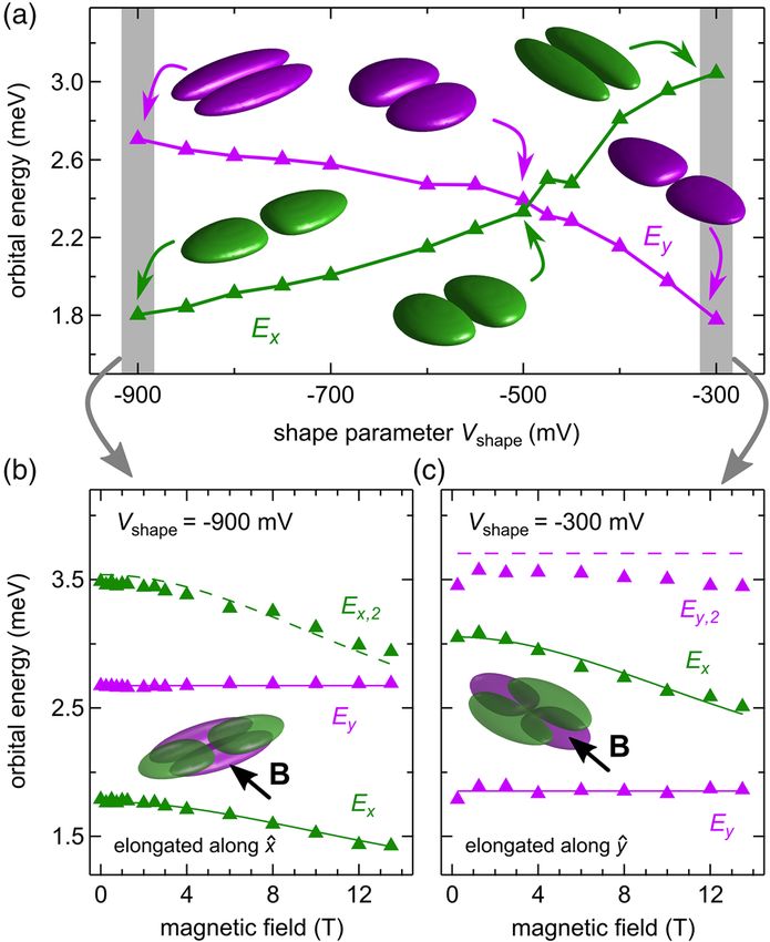
PHYSICAL REVIEW LETTERS 122, 207701 (2019)

the quantum mechanical orbitals of a quantum dot with
subnanometer precision. It is based on a response of the
energy spectrum to an in-plane magnetic field of varying
magnitude and direction. The theoretical principles of the
method are explained in Ref. [16]. Here, we demonstrate it
experimentally. While our quantitative interpretation of
the measurements is based on assuming an asymmetric
(triangular) 2DEG confinement and a harmonic in-plane
confinement, the method is directly applicable to any quasi-
two-dimensional system for which the unperturbed con-
finement can be reasonably guessed.
   The surface gate layout of the measured device, shown in
Fig. 1(a), is based on Ref. [3]. The device is biased into
the single-electron quantum dot regime, as indicated by
the red ellipsoid. The dot is tuned to couple to the left
reservoir only, with a tunnel rate between 1 and 100 Hz. An
additional quantum dot, located directly adjacent to the
main dot, serves as a charge sensor [22,23], giving a change
of sensor conductance of up to 100% per electron in the
main dot. The sample can be oriented with an essentially
arbitrary angle with respect to an in-plane magnetic field up
to 14 T using a piezoelectric rotator. Using standard van der
Pauw measurements, the magnetic field is shown to deviate
less than 1.3° out of the 2DEG plane, thus rendering the
out-of-plane component negligible [6]. Measurements are
done in a dilution refrigerator with an electron temperature
of 60 mK [24–26].
   The orbital energies are measured by pulsed-gate spec-       FIG. 1. (a) Sketch with electron micrograph of the gate layout
troscopy using a three-step pulse sequence. Namely, an          of a cofabricated device shown on top. The gate left wall (LW),
additional voltage ΔV P is applied to the center plunger gate   right wall (RW), left plunger (LP), center plunger (CP), right
(CP), on top of the static gate voltage V P [see Fig. 1(a)]     plunger (RP) and nose (N) form the quantum dot (QD). The
[3,27,28]. As illustrated in Fig. 1(b), the sequence consists   sensor quantum dot (SQD) is adjacent to the left. The
of initialization, charging, and readout steps (see also        GaAs=Al0.3 Ga0.7 As heterostructure contains a 2DEG with den-
Sec. V in the Supplemental Material [17]). The elastic          sity 2.6 × 1011 cm−2 and mobility 4 × 105 cm2 =V s located
                                                                110 nm below the surface. The in-plane field angle ϕ and wave
tunnel rate into the empty dot increases sharply when an
                                                                function orientation δ are defined with respect to [100], while
orbital state becomes resonant with the chemical potential μ
                                                                δ̃ ¼ δ − 225° is the angle between x̂ ¼ ½1̄ 1̄ 0 and x̂d , the dot
of the reservoir. By measuring the dot-reservoir tunnel         confinement x axis. (b) Three-step pulse sequence described in
coupling for varying ΔV P , individual excited orbital states   the text. (c) Measurement of tunneling-in rate Γin as a function of
can be distinguished. An example is shown in Fig. 1(c)          ΔV P exhibiting three excited orbital states at energies Ex , Ey , and
exhibiting three excited orbital states. The ground state,      Ex;2 . (d) Ground-state wave function (left) and the p-type orbitals
which calibrates ΔV P ¼ 0, couples much weaker to the           for an elongated dot with exaggerated anisotropy (details in Sec. I
reservoir (ΓGS ∼ 10 Hz) compared to the excited orbital         of the Supplemental Material [17]).
states, attributed to the increased spatial extent of higher
orbitals [29,30]. The exponential decay in the tunnel rate of
the excited states with increasing ΔV P [dashed curves in       much stronger confinement for the heterostructure growth
Fig. 1(c)] is due to an increasing tunnel barrier [31–33].      direction (ẑ) coordinate,
Finally, we note that our method requires that the probe
voltage does not change the confinement potential. We                               p2   ℏ2 x2d y2d
                                                                              H¼       þ       þ      þ vðzÞ:                     ð1Þ
conclude that this assumption is well met, as the pulse ΔV P                        2m 2m l4x l4y
is much smaller (typically, tens of millivolts, applied only
on one gate) than voltages required to change the dot shape     Here, p is the momentum operator, ℏ is the reduced Planck
substantially (typically hundreds of millivolts, applied on     constant, m is the effective mass, and lx;y are the confine-
all gates), as deduced from Fig. 2(a).                          ment lengths along the main axes x̂d and ŷd of the in-plane
   We assume that the dot confinement separates into a 2D       confinement. These axes are, in general, rotated from the
harmonic oscillator part for the in-plane coordinates and a     crystal axes [100] and [010] by an angle δ [see Figs. 1(a)

                                                          207701-2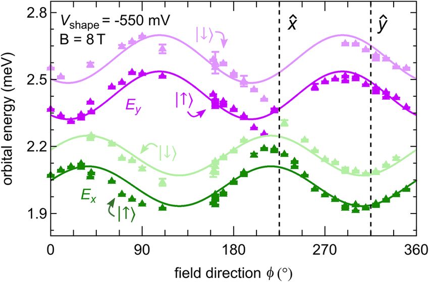
PHYSICAL REVIEW LETTERS 122, 207701 (2019)
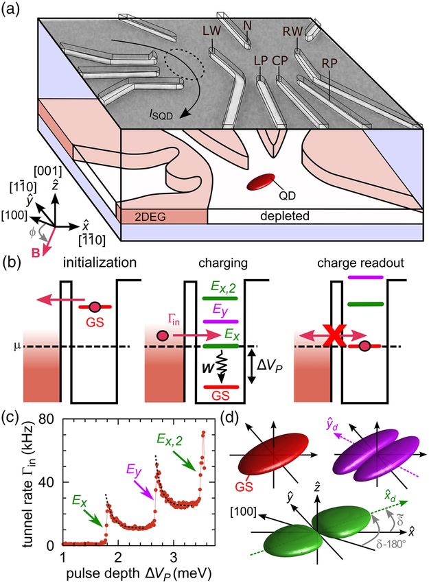
V shape to denote the full set of gate voltages corresponding to
a particular configuration (see Fig. 2), with the numerical
value of V shape taken to be the voltage on gate CP.
The two lowest orbital excitation energies are shown in
Fig. 2(a) as a function of the dot shape V shape . Upon making
V shape more negative, thus squeezing the dot in the ŷ
direction, one of the two energies increases, thus identified
as the ŷ state. The other energy decreases and thus has to
be the x̂ state, as labeled in Fig. 2. Interestingly, at
V shape ∼ −500 mV, we find Ex ≈ Ey , indicating a circular,
isotropic wave function in the 2D plane. Such shape
manipulation by gate voltages is limited, on one hand,
by the minimum voltage needed to deplete the 2DEG
underneath the surface gates and, on the other hand, by
the gate leakage threshold at more negative gate voltages.
We emphasize that, throughout the shape manipulation, the
tunneling rate to the reservoir is held approximately
constant. For each dot shape, the relevant lever arm is
measured, providing the gate voltage to energy conversion
in order to obtain the excited-state energies from pulsed-gate
spectroscopy (see Sec. IV in the Supplemental Material [17]
for details).
From such data, however, there is no estimate of the tilt
angle δ̃ or how it depends on V shape —other than that it is
probably not too big. It is natural to expect that, as the dot is
FIG. 2. (a) Orbital excitation energies Ex (green) and Ey
being squeezed, the wave function is also shifted and
(purple) as a function of V shape . The schematics give a qualitative
possibly somewhat rotated in space, depending on the
picture of the excited orbital wave functions along the x̂ direction
(green) and ŷ direction (purple) for the three shapes indicated by detailed potential and disorder landscape present. In addi-
the arrows. Less exaggerated wave functions are shown in Sec. I tion, we note that the subband excitations Ez ≫ Ex;y are
of the Supplemental Material [17]. Orbital excitation energies for energetically out of reach of this pulsed-gate spectroscopy
a magnetic field applied along the y direction for two extreme dot method, so that little can be said about the size of the dot
shapes elongated (b) along x̂ and (c) along ŷ, for V shape as labeled. orbitals along the growth axis. We are now going to show
The data are fitted to Eq. (4), giving λz ¼ 6.3 0.3 nm and Ez ¼ how this missing information can be revealed; this is the
28.6 3 meV [34]. main advance that our work makes.
To this end, we exploit the effects of a strong in-plane
magnetic field B applied along an in-plane direction b̂,
and 1(d)]. For simplicity, we introduce δ̃ ¼ δ − 225° as the
which makes an angle ϕ with the [100] crystallographic
angle between potential axis x̂d and device axis x̂ ¼ ½1̄ 1̄ 0. axis [see coordinate system in Fig. 1(a)]. In Ref. [16], we
In the model described by Eq. (1), the excitation energies show that the leading order effect can be expressed as a
are Ex;y ¼ ℏ2 =ml2x;y and the ground-state wave function can correction to Eq. (1) of the following form [35]:
be represented by a disklike ellipsoid. The two lowest
excited states correspond to p-like orbitals aligned along Φ2
δH ¼ − ½p · ðb̂ × ẑÞ2 : ð2Þ
two perpendicular axes x̂d , ŷd , as shown in Fig. 1(d). 2m
Within this model, the parameters Ex , Ey , and δ
This interaction is the basis for our spectroscopy. Its
characterize the dot shape, and vice versa, control of these
strength scales with the magnetic flux Φ penetrating the
parameters indicates dot-shape tunability. This is what we
2DEG due to its finite width. Explicitly,
demonstrate next. Applying appropriate voltages on the
surface gates, the dot can be elongated either in the x̂ or, e 2
alternatively, the ŷ direction [3]. For instance, the dot can be Φ¼ Bλ ; ð3Þ
ℏ z
squeezed in the ŷ direction by applying more negative
voltages on the plunger gates LP, CP, and RP [see Fig. 1(a)]. where e > 0 is the elementary charge and λz is the effective
To keep the ground-state energy constant, these changes are width of the wave function along the growth direction. We
compensated by applying less negative voltages on the other analyze the connection between a nominal width and the
gates LW and RW, which leads to an expansion of the wave effective width of a 2DEG for several confinement pro-
function in the x̂ direction. We introduce a shape parameter files, namely, triangular, harmonic, and a square potential
207701-3PHYSICAL REVIEW LETTERS 122, 207701 (2019)
well [16]. Also, we note that flux threading was previously
studied in open dots [36–38].
For typical 2DEGs and magnetic fields, the flux is small:
Φ ≪ 1 [34]. Treating Eq. (2) as a perturbation to Eq. (1),
the energies change by
Φ 2 ℏ2
δEx;y ¼ − sin2 ðδx;y − ϕÞ: ð4Þ
2 ml2x;y
Here, we denoted δx;y as the corresponding excited orbital
directions (with respect to [100]). They follow from Eq. (1)
as δx ¼ δ and δy ¼ δ þ π=2.
First, we apply a strong magnetic field along the y
direction for the two most elongated shapes available [see
Figs. 2(b) and 2(c)]. For sufficiently weak confinement FIG. 3. Spin-resolved excitation energies measured at the
magnetic field of a fixed magnitude 8 T and varying direction
along one direction, a second excited state Ex;2 or Ey;2
in an almost circular quantum dot (V shape ∼ −550 mV in Fig. 2).
also becomes accessible. While Ex;2 ∼ 2Ex for the dot in The solid curves show a fit according to Eq. (4) for each orbital
Fig. 2(b), Ey;2 is slightly lower in energy than the second state (separately for the green and purple data) assuming a
harmonic of Ey , as seen in Fig. 2(c). For this configuration, direction-independent Zeeman energy. Since the g factor
the voltage on the nose N and all plunger gates are only anisotropy is small [40], this is a very good approximation.
barely sufficient to deplete the 2DEG, which could lead to The fit gives δ̃x ¼−8°4°, δ̃y ¼ 62° 4°, and λz ¼ 6.1 0.3 nm
a softening of the confinement potential along ŷ. Looking (Ez ¼ 30.7 3 meV) [34].
at the field dependence, we make the striking observation
that Ey remains constant for both shapes, while Ex clearly
knowledge on the quantum dot size along the growth
changes with magnetic field. This is consistent with the direction is essential for quantitative analysis of spin
notion that the orbital effects of a magnetic field are given properties, such as relaxation [6].
by a Lorentz force, which is a vector product of the velocity We now turn to a precise quantification of the dot
with the field, thus leaving motion along the direction of the orientation. It can be done by measuring the excitation
applied field unaffected. This agrees with the prediction of energies at a magnetic field with fixed magnitude and varied
Eq. (2), giving that x̂d ≈ x̂, meaning that the dot is oriented orientation. Figure 3 presents such data for B ¼ 8 T and a
along the device axes. The invariance of Ey indicates that more symmetric dot. The energies show a sinusoidal behav-
the corresponding orbital is rather well aligned with the ior as expected from Eq. (4). The two states oscillate out
magnetic field and therefore the y axis of the device. of phase, proving that they represent orbitals oriented
Comparing the two cases in Fig. 2, we emphasize that, perpendicular to each other (see also Sec. III in the
going from Fig. 2(b) to 2(c), the quantum dot was in fact Supplemental Material [17]). For an elongated (quasi-1D)
rotated by 90°, thus demonstrating a gate-induced quantum dot, the states would oscillate in phase [16]. Beyond
dot rotation. Indeed, this is expected from the gate voltage confirming that our dot is indeed close to a symmetric
dependence V shape and is here validated in real space with one, we can specify its orientation in detail. By fitting the data
the in-plane field spectroscopy. of Fig. 3 to Eqs. (1) and (2), we obtain δ̃ ¼ −8° 4°,
By fitting the data to Eqs. (3) and (4), we can extract the indicating the dot is slightly tilted away from the device
effective width λz and thus the size of the quantum dot coordinate system. We note that even such modest misalign-
along the growth direction. We can convert the latter, under ment can have a large impact on the qubit quality [10] and on
a rather mild assumption that the heterostructure confine- characterization of the spin-orbit fields [4].
ment is triangular, to the interface electric field Eext and Before concluding, we look at the assumption that the
the subband energy splitting Ez . This in turn allows for in-plane confinement is a quadratic function of coordinates,
the evaluation of the spin-orbit fields. Namely, from λz ¼ adopted in Eq. (1). It has been used from the onset of
6.3 0.3 nm, we get the spin-orbit lengths lr ¼ 2.1 quantum dot investigations [11] as a practical choice for
0.3 μm and ld ¼ 3.2 0.3 μm for the Rashba and which analytical solutions are known [41–43]. Compared
Dresselhaus interaction, respectively [39]. Using an inde- to its prevalent use, the evidence on such confinement
pendent fit from the directional variation of the spin- shape is less abundant and has, until now, been restricted to
relaxation time [6] gave lr ¼ 2.5 0.2 μm and ld ¼ 4.1 checking the equidistant energy spacing of excited states of
0.4 μm illustrating the agreement. We point out that, apart a harmonic oscillator. The data in Fig. 3 can provide
from determining the spin-orbit interactions strengths, the additional information. Namely, fitting each of the acces-
width of the 2DEG determines also the strength the electron sible orbitals to Eq. (4) individually, we can extract the x, y
Fermi contact interaction with nuclear spins. Thus, orbital-specific angle δx;y . In principle, one can map out the
207701-4PHYSICAL REVIEW LETTERS 122, 207701 (2019)
dependence of δ on the single-particle state energy, if more [7] S. I. Erlingsson and Y. V. Nazarov, Phys. Rev. B 66, 155327
excited states are accessible. Here, we find δy −δx ≈708°. (2002).
It is different from 90°, a value for a purely quadratic [8] K. C. Nowack, F. H. L. Koppens, Y. V. Nazarov, and L. M. K.
Vandersypen, Science 318, 1430 (2007).
potential, and here we have quantified by how much.
[9] M. Pioro-Ladrière, T. Obata, Y. Tokura, Y.-S. Shin, T. Kubo,
In summary, we measure excitation energies in a single-
K. Yoshida, T. Taniyama, and S. Tarucha, Nat. Phys. 4, 776
electron lateral quantum dot with in-plane magnetic fields (2008).
of varying orientation. We show that such measurement [10] O. Malkoc, P. Stano, and D. Loss, Phys. Rev. B 93, 235413
can determine the orientation of the dot and extract its (2016).
single-particle quantum mechanical confinement parame- [11] S. M. Reimann and M. Manninen, Rev. Mod. Phys. 74,
ters. In particular, this means that, for a given orbital, one 1283 (2002).
can assign a size and orientation within the 2DEG plane, as [12] R. Hanson, L. P. Kouwenhoven, J. R. Petta, S. Tarucha, and
well as its extension along the growth direction with L. M. K. Vandersypen, Rev. Mod. Phys. 79, 1217 (2007).
subnanometer resolution. The information on the quantum [13] M. A. Topinka, B. J. LeRoy, R. M. Westervelt, S. E. J. Shaw,
dot shape has an immediate use in correct quantification of R. Fleischmann, E. J. Heller, K. D. Maranowski, and A. C.
the spin-orbit fields, as well as the strength of the electron- Gossard, Nature (London) 410, 183 (2001).
[14] A. Pioda, S. Kičin, T. Ihn, M. Sigrist, A. Fuhrer, K. Ensslin,
nuclear Fermi contact hyperfine interaction. We note that
A. Weichselbaum, S. E. Ulloa, M. Reinwald, and W.
the method is directly applicable to any quasi-2D dot, also Wegscheider, Phys. Rev. Lett. 93, 216801 (2004).
in other materials and more sophisticated structures, for [15] M. Stopa, Phys. Rev. B 54, 13767 (1996).
example, triple quantum dot devices with noncollinear [16] P. Stano, C.-H. Hsu, L. C. Camenzind, L. Yu,
arrangement, as well as dots with higher electron occupa- D. M. Zumbühl, and D. Loss, Phys. Rev. B 99, 085308
tions, where Hartree-Fock orbitals could be accessed in the (2019).
same way. [17] See Supplemental Material at http://link.aps.org/
The data that support the findings of this study are supplemental/10.1103/PhysRevLett.122.207701 for wave
available in a Zenodo repository [44]. functions, in-plane B-field energy corrections, orbital spec-
tra, lever arms, and measurement details, including
We thank V. Golovach for valuable inputs and stimu- Refs. [18–21].
lating discussions, M. Steinacher and S. Martin for tech- [18] S. Gustavsson, R. Leturcq, B. Simovič, R. Schleser, P.
nical support, and Basel Precision Instruments GmbH for Studerus, T. Ihn, K. Ensslin, D. C. Driscoll, and A. C.
specialized electronics, such as preamplifiers and voltage Gossard, Phys. Rev. B 74, 195305 (2006).
sources. This work was supported by the Swiss [19] L. Casparis, M. Meschke, D. Maradan, A. C. Clark, C. P.
Nanoscience Institute (SNI), NCCR QSIT, Swiss NSF, Scheller, K. K. Schwarzwälder, J. P. Pekola, and D. M.
ERC starting grant (DMZ), and the European Microkelvin Zumbühl, Rev. Sci. Instrum. 83, 083903 (2012).
[20] S. D. Liles, R. Li, C. H. Yang, F. E. Hudson, M. Veldhorst,
Platform (EMP). P. S. acknowledges support from
A. S. Dzurak, and A. R. Hamilton, Nat. Commun. 9, 3255
CREST JST (JPMJCR1675) and JSPS Kakenhi Grant (2018).
No. 16K05411.National Center of Competence in [21] P. Stano and J. Fabian, Phys. Rev. B 77, 045310 (2008).
Research Quantum Science and Technology [22] M. Field, C. G. Smith, M. Pepper, D. A. Ritchie, J. E. F.
Frost, G. A. C. Jones, and D. G. Hasko, Phys. Rev. Lett. 70,
1311 (1993).
[23] C. Barthel, M. Kjargaard, J. Medford, M. Stopa, C. M.
*
Corresponding author. Marcus, M. P. Hanson, and A. C. Gossard, Phys. Rev. B 81,
dominik.zumbuhl@unibas.ch 161308(R) (2010).
† [24] C. P. Scheller, S. Heizmann, K. Bedner, D. Giss, M.
Present address: Physics Department, Colorado School of
Mines, Golden, Colorado 80401, USA. Meschke, D. M. Zumbühl, J. D. Zimmerman, and A. C.
[1] D. Loss and D. P. DiVincenzo, Phys. Rev. A 57, 120 (1998). Gossard, Appl. Phys. Lett. 104, 211106 (2014).
[2] C. Kloeffel and D. Loss, Annu. Rev. Condens. Matter Phys. [25] D. Maradan, L. Casparis, T.-M. Liu, D. E. F. Biesinger, C. P.
4, 51 (2013). Scheller, D. M. Zumbühl, J. D. Zimmerman, and A. C.
[3] S. Amasha, K. MacLean, I. P. Radu, D. M. Zumbühl, M. A. Gossard, J. Low Temp. Phys. 175, 784 (2014).
Kastner, M. P. Hanson, and A. C. Gossard, Phys. Rev. Lett. [26] D. E. F. Biesinger, C. P. Scheller, B. Braunecker, J.
100, 046803 (2008). Zimmerman, A. C. Gossard, and D. M. Zumbühl, Phys.
[4] P. Scarlino, E. Kawakami, P. Stano, M. Shafiei, C. Reichl, Rev. Lett. 115, 106804 (2015).
W. Wegscheider, and L. M. K. Vandersypen, Phys. Rev. [27] J. M. Elzerman, R. Hanson, L. H. Willems Van Beveren,
Lett. 113, 256802 (2014). L. M. K. Vandersypen, and L. P. Kouwenhoven, Appl. Phys.
[5] V. N. Golovach, A. Khaetskii, and D. Loss, Phys. Rev. Lett. Lett. 84, 4617 (2004).
93, 016601 (2004). [28] A. C. Johnson, C. M. Marcus, M. P. Hanson, and A. C.
[6] L. C. Camenzind, L. Yu, P. Stano, J. D. Zimmerman, A. C. Gossard, Phys. Rev. B 71, 115333 (2005).
Gossard, D. Loss, and D. M. Zumbühl, Nat. Commun. 9, [29] T. Fujisawa, Y. Tokura, and Y. Hirayama, Phys. Rev. B 63,
3454 (2018). 081304(R) (2001).
207701-5PHYSICAL REVIEW LETTERS 122, 207701 (2019)
[30] R. Hanson, B. Witkamp, L. M. K. Vandersypen, L. H. [37] D. M. Zumbühl, J. B. Miller, C. M. Marcus, V. I. Fal’ko, T.
Willems van Beveren, J. M. Elzerman, and L. P. Jungwirth, and J. S. Harris, Phys. Rev. B 69, 121305(R)
Kouwenhoven, Phys. Rev. Lett. 91, 196802 (2003). (2004).
[31] K. MacLean, S. Amasha, I. P. Radu, D. M. Zumbühl, M. A. [38] D. M. Zumbühl, J. B. Miller, C. M. Marcus, D. Goldhaber-
Kastner, M. P. Hanson, and A. C. Gossard, Phys. Rev. Lett. Gordon, J. S. Harris, K. Campman, and A. C. Gossard,
98, 036802 (2007). Phys. Rev. B 72, 081305(R) (2005).
[32] S. Amasha, K. MacLean, I. P. Radu, D. M. Zumbühl, M. A. [39] The error intervals on the spin-orbit lengths given here are
Kastner, M. P. Hanson, and A. C. Gossard, Phys. Rev. B 78, due to the uncertainty in λz . We do not reflect additional
041306(R) (2008). uncertainty, stemming from the conversion factors (basi-
[33] P. Stano and P. Jacquod, Phys. Rev. B 82, 125309 (2010). cally, uncertainty in parameters of the k · p theory).
[34] A generalization beyond this regime is given in Supple- [40] P. Stano, C.-H. Hsu, M. Serina, L. C. Camenzind, D. M.
mental Material Sec. 2 and Ref. [16] and boils down to the Zumbühl, and D. Loss, Phys. Rev. B 98, 195314 (2018).
replacement Φ2 → 1 − 1=ð1 þ Φ2 Þ in Eqs. (2) and (4), [41] B. Schuh, J. Phys. A 18, 803 (1985).
which was used in fitting the data here, too. A more [42] I. M. Davies, J. Phys. A 18, 2737 (1985).
sophisticated fitting, beyond the perturbative regime, can [43] T. K. Rebane, Theor. Exp. Chem. 5, 1 (1972).
be done straightforwardly [16], leading to only small [44] L. C. Camenzind, L. Yu, P. Stano, J. D. Zimmerman, A. C.
changes in the values of extracted parameters. Gossard, D. Loss, D. M. Zumbühl, Supporting data
[35] F. Stern, Phys. Rev. Lett. 21, 1687 (1968). for spectroscopy of quantum dot orbitals with in-plane
[36] V. I. Fal’ko and T. Jungwirth, Phys. Rev. B 65, 081306(R) magnetic fields (2019), https://doi.org/10.5281/zenodo
(2002). .2652371.
207701-6You can also read