Swimming freely near the ground leads to flow-mediated equilibrium altitudes - CDN
←
→
Page content transcription
If your browser does not render page correctly, please read the page content below
Downloaded from https://www.cambridge.org/core. Lehigh University, on 18 Jul 2019 at 13:16:21, subject to the Cambridge Core terms of use, available at https://www.cambridge.org/core/terms. https://doi.org/10.1017/jfm.2019.540
J. Fluid Mech. (2019), vol. 875, R1, doi:10.1017/jfm.2019.540
journals.cambridge.org/rapids
Swimming freely near the ground leads to
flow-mediated equilibrium altitudes
Melike Kurt1, †, Jackson Cochran-Carney1 , Qiang Zhong2 ,
Amin Mivehchi1 , Daniel B. Quinn2 and Keith W. Moored1
1 Department of Mechanical Engineering, Lehigh University, Bethlehem, PA 18015, USA
2 Department of Aerospace and Mechanical Engineering, University of Virginia, Charlottesville,
VA 22904, USA
(Received 29 April 2019; revised 28 June 2019; accepted 28 June 2019)
Experiments and computations are presented for a foil pitching about its leading
edge near a planar, solid boundary. The foil is examined when it is constrained in
space and when it is unconstrained or freely swimming in the cross-stream direction.
It was found that the foil has stable equilibrium altitudes: the time-averaged lift is
zero at certain altitudes and acts to return the foil to these equilibria. These stable
equilibrium altitudes exist for both constrained and freely swimming foils and are
independent of the initial conditions of the foil. In all cases, the equilibrium altitudes
move farther from the ground when the Strouhal number is increased or the reduced
frequency is decreased. Potential flow simulations predict the equilibrium altitudes to
within 3 %–11 %, indicating that the equilibrium altitudes are primarily due to inviscid
mechanisms. In fact, it is determined that stable equilibrium altitudes arise from an
interplay among three time-averaged forces: a negative jet deflection circulatory
force, a positive quasistatic circulatory force and a negative added mass force. At
equilibrium, the foil exhibits a deflected wake and experiences a thrust enhancement
of 4 %–17 % with no penalty in efficiency as compared to a pitching foil far from the
ground. These newfound lateral stability characteristics suggest that unsteady ground
effect may play a role in the control strategies of near-boundary fish and fish-inspired
robots.
Key words: flow–structure interactions, propulsion, swimming/flying
1. Introduction
Airfoils have long been known to have reduced downwash and high lift-to-drag
ratios near the ground (Cui & Zhang 2010). This ‘steady ground effect’ has inspired
the design of several wing-in-ground effect aircraft (Rozhdestvensky 2006). In nature,
† Email address for correspondence: mek514@lehigh.edu
c Cambridge University Press 2019 875 R1-1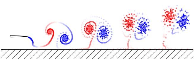
Downloaded from https://www.cambridge.org/core. Lehigh University, on 18 Jul 2019 at 13:16:21, subject to the Cambridge Core terms of use, available at https://www.cambridge.org/core/terms. https://doi.org/10.1017/jfm.2019.540
M. Kurt and others
animals such as birds and flying fish use steady ground effect to improve their cost of
transport or gliding distance (Hainsworth 1988; Rayner 1991; Park & Choi 2010). In
contrast, some fish exploit unsteady ground effect to improve their cost of transport
or cruising speed when swimming near substrates and sidewalls (Blake 1983; Webb
1993, 2002; Nowroozi et al. 2009; Blevins & Lauder 2013), and it is important in the
take-off and landing of insects (Van Truong et al. 2013a,b). In unsteady ground effect,
fin/wing/tail/body oscillations create time-dependent wakes and continuous fluctuations
in the pressure field. Unsteady ground effect differs from steady ground effect in that
it produces thrust enhancement, a ubiquitous deflection of wake momentum away from
the ground, and negative lift regimes at moderate ground proximities on the order of
a chord length (Quinn et al. 2014b).
Unsteady ground effect was first examined through the development of analytical
models for a fluttering plate in a channel (Tanida 2001) and for an oscillating wing
in weak ground effect (Iosilevskii 2008), but these only apply in extreme cases, such
as flying/swimming very far from or very close to the ground. At more moderate
ground proximities, experiments and computations have shown that rigid (Quinn et al.
2014b; Mivehchi, Dahl & Licht 2016; Perkins et al. 2018) and flexible (Blevins &
Lauder 2013; Quinn, Lauder & Smits 2014a; Fernández-Prats et al. 2015; Dai, He
& Zhang 2016; Park, Kim & Sung 2017; Zhang, Huang & Lu 2017) oscillating foils
and wings can have improved thrust production with little or no penalty in efficiency
when operating in unsteady ground effect. Additionally, Quinn et al. (2014b) found
both negative and positive time-averaged lift regimes for constrained (as opposed to
freely swimming) pitching foils near the ground. They hypothesized that a freely
swimming pitching foil would settle into an equilibrium altitude as fluid-mediated
forces pushed the foil to the edge of these lift regimes. This surprising result was
shown for a constrained foil within a potential flow numerical framework (Quinn et al.
2014b), leaving open questions as to whether viscosity and/or recoil motions would
disrupt the existence of these equilibrium altitudes. Recent tow tank experiments
provided more evidence for equilibrium altitudes by finding negative and positive lift
zones for constrained, near-ground, heaving and pitching foils (Mivehchi et al. 2016).
Recent low-Reynolds-number (Re = 100) computations of near-ground, flexible, freely
swimming plates also found equilibrium altitudes, but could not test whether the
altitudes persist at high Reynolds numbers (Kim et al. 2017). No previous work has
experimentally confirmed the equilibrium altitudes for freely swimming foils, nor is
it known whether the equilibrium altitudes are affected by swimming kinematics.
Motivated by these observations, we present new experiments and computations
aimed at probing the existence of equilibrium altitudes and their dependence upon
non-dimensional variables for high-Reynolds-number swimmers operating in unsteady
ground effect. We consider two pitching foil systems: one constrained to fixed
positions and another unconstrained and free to move in the cross-stream direction.
Two main questions are considered: do equilibrium altitudes exist for an oscillating
foil in the presence of a solid boundary, and if so, how are they affected by swimming
variables such as the Strouhal number and reduced frequency?
2. Methods
The hydrofoil used throughout this study has a rectangular-planform shape, a
7 % thick tear-drop cross-section (Godoy-Diana, Aider & Wesfreid 2008; Quinn
et al. 2014b), and a chord and span length of c = 0.095 m and s = 0.19 m
(A = 2), respectively. It was fabricated out of acrylonitrile butadiene styrene (ABS).
875 R1-2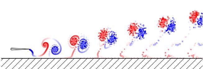
Downloaded from https://www.cambridge.org/core. Lehigh University, on 18 Jul 2019 at 13:16:21, subject to the Cambridge Core terms of use, available at https://www.cambridge.org/core/terms. https://doi.org/10.1017/jfm.2019.540
Unsteady ground effect flow-mediated equilibrium altitudes
Constrained experiments Unconstrained experiments/simulations
∗
A 0.125, 0.25, 0.38, 0.49, 0.61 0.15, 0.2, 0.25, 0.3
D∗ 0.25–2.6 —
D∗0 — 0.25, 0.5, 0.75
St 0.06–0.63 0.3, 0.4, 0.5
k 0.52, 0.77, 1.02 0.5, 0.75, 1
TABLE 1. Experimental and numerical variables used in the constrained and
unconstrained foil experiments, and the unconstrained simulations.
The hydrofoil was actuated with pure pitching motion about its leading edge by a
digital servo motor (constrained experiments: Dynamixel MX-64AT, unconstrained
experiments: Dynamixel MX-64), and the angular position was tracked by an optical
encoder (constrained experiments: US Digital E5, unconstrained experiments: US
Digital A2K 4096 CPR). The prescribed sinusoidal motion can be defined as
θ(t) = θ0 sin(2πft), where f is the frequency of the motion, t is the time and θ0
is the pitching amplitude. Measurements were taken throughout this study at three
flapping frequencies: f = 0.5, 0.75 and 1 Hz. The frequency is also used to defined
the reduced frequency, k ≡ fc/U, and the Strouhal number, St ≡ fA/U. Here A is the
peak-to-peak amplitude of motion – that is, A = 2c sin θ0 . The amplitude of motion
is reported in its non-dimensional form as A∗ = A/c. One of the primary variables
of the current study is the non-dimensional ground distance, D∗ = D/c, where D is
the distance from the ground plane. Throughout the current study, the flow speed, U,
was kept at 0.093 m s−1 , giving a chord-based Reynolds number of 9950. The input
variables used are summarized in table 1.
For the constrained experiments and the simulations, the force production is
measured and reported as the time-averaged thrust, T, lift, L, and power, P, normalized
by the dynamic pressure and planform area:
T L P CT
CT ≡ , CL ≡ , CP ≡ , η≡ , (2.1a−d)
1
2
ρU 2 cs 1
2
ρU 2 cs 1
2
ρU 3 cs CP
where ρ is the density of the fluid medium and η is the propulsive efficiency. Here, the
time-averaged power from the simulations is the time average of the pitching moment
and the angular rate – that is, P = Mθ θ̇.
2.1. Constrained foil experiments
Constrained foil experiments were conducted in a closed-loop water channel with a
test section of 4.9 m long, 0.93 m wide and 0.61 m deep. In order to produce a
nominally two-dimensional flow, a splitter and surface plate were installed near each
hydrofoil tip (see figure 1a). A vertical ground wall was also installed on the side of
the channel, as shown in figure 1(a). Five different non-dimensional amplitudes were
tested: A∗ = 0.125, 0.25, 0.38, 0.49 and 0.61. The non-dimensional ground distance
was varied within the range 0.25 6 D∗ 6 2.6. Lift measurements were conducted with
a six-axis force sensor (ATI Nano43). The lift data were time-averaged over 100
oscillation cycles, and each reported data point is the mean value of five trials.
875 R1-3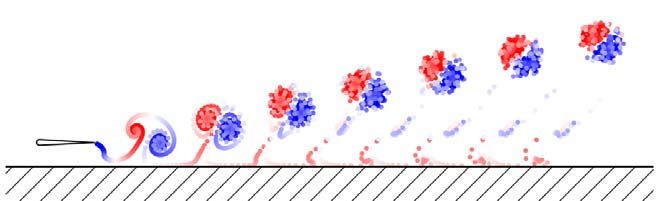
Downloaded from https://www.cambridge.org/core. Lehigh University, on 18 Jul 2019 at 13:16:21, subject to the Cambridge Core terms of use, available at https://www.cambridge.org/core/terms. https://doi.org/10.1017/jfm.2019.540
M. Kurt and others
(a) (b) Compressed air tank
Servo motor Force sensor Air bearing
Surface plate Laser distance sensor
Servo motor Surface plate
Ground wall
U Foil U
Foil
Splitter plate
Splitter plate
F IGURE 1. Schematic of the (a) constrained pitching hydrofoil set-up and
(b) unconstrained hydrofoil set-up.
2.2. Foil experiments unconstrained in the cross-stream direction
Tests were also conducted for a pitching hydrofoil that was unconstrained in the
cross-stream direction. The unconstrained hydrofoil was in a closed-loop water
channel with a test section of 1.52 m long, 0.38 m wide and 0.45 m deep (Rolling
Hills 1520). The hydrofoil was suspended from three air bushings (New Way
S301901), giving it near-frictionless cross-stream freedom while constraining it in the
streamwise direction (figure 1b). The compressed air was stored in a 4500 psi tank
that moved with the hydrofoil, and the airflow was controlled by a programmable
solenoid valve. A nominally two-dimensional flow was achieved by installing a
horizontal splitter plate and a surface plate near the tips of the hydrofoil (figure 1b).
The gap between the hydrofoil tips and the surface/splitter plate was less than 5 mm.
Surface waves were also minimized by the presence of the surface plate.
The wall of the channel was used as a ground plane, and the ground distance was
recorded by a laser distance sensor (Baumer CH-8501). The hydrofoil was placed
at three initial positions: D∗0 = 0.25, 0.5 and 0.75. Each trial included at least 80
oscillation cycles. To eliminate any drag caused by cables, all angular position and
laser sensor data were synchronized by a custom circuit and transmitted to a control
PC (Omen 870) via wifi (ATI Wireless F/T).
2.3. Foil simulations unconstrained in the cross-stream direction
Potential flow simulations were employed to exactly match the foil experiments
unconstrained in the cross-stream direction since previous potential flow numerical
solutions for the constrained foil case have been reported (Quinn et al. 2014b). The
matching of the experiments and simulations provides a direct means of assessing
the role of viscosity. To model the flow over a foil unconstrained in the cross-stream
direction, we used a two-dimensional boundary element method (BEM) based on
potential flow theory in which the flow is assumed to be irrotational, incompressible
and inviscid. By following previous studies (Katz & Plotkin 2001; Quinn et al.
2014b; Moored 2018), the general solution to the potential flow problem is reduced
to finding a distribution of sources and doublets on the foil surface and in its wake.
At each time step a no-flux boundary condition is enforced on the body.
To solve this problem numerically, constant-strength source and doublet line
elements are distributed over the body and the wake. Each body element is assigned
a collocation point, which is located at the centre of each element and shifted 1 %
of local thickness into the body, where a constant-potential condition is applied to
enforce no flux through the surface (i.e. Dirichlet formulation). This results in a
matrix representation of the boundary condition that can be solved for the body
875 R1-4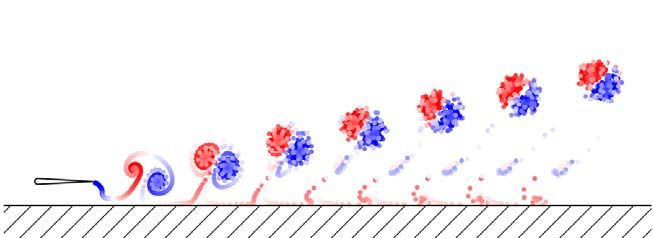
Downloaded from https://www.cambridge.org/core. Lehigh University, on 18 Jul 2019 at 13:16:21, subject to the Cambridge Core terms of use, available at https://www.cambridge.org/core/terms. https://doi.org/10.1017/jfm.2019.540
Unsteady ground effect flow-mediated equilibrium altitudes
doublet strengths once a wake shedding model is applied. Additionally, at each
time step, a wake boundary element is shed with a strength that is set by applying
an explicit Kutta condition, where the vorticity at the trailing edge is set to zero
(Willis 2006; Wie, Lee & Lee 2009; Pan et al. 2012). A wake roll-up algorithm
is implemented at each time step where the wake elements are advected with the
local velocity. During wake roll-up, the point vortices, representing the ends of
the wake doublet elements, must be desingularized for numerical stability of the
solution (Krasny 1986). At a cutoff radius of /c = 5 × 10⁻² , the irrotational induced
velocities from the point vortices are replaced with a rotational Rankine core model.
The tangential perturbation velocity component is calculated by local differentiation
of the perturbation potential. The pressure acting on the body is found via applying
the unsteady Bernoulli equation. Moreover, the mean thrust force is calculated as
the time average of the streamwise-directed pressure forces, and the time-averaged
power input to the fluid is calculated as the time average of the negative inner
productR of the force vector and velocity vector of each boundary element – that is,
P = − S Fele · uele dS , where S is the body surface.
The presence of the ground is modelled using the method of images, which
automatically satisfies the no-flux boundary condition on the ground plane. The foil
is also given a mass, m, equal to the effective mass of the moving portion of the
apparatus in the unconstrained foil experiments, and is non-dimensionalized by the
characteristic added mass of the hydrofoil as m∗ = m/(ρsc2 ) = 2.68. At each time step
the equation of motion in the cross-flow direction is solved through a one-way explicit
coupling between the fluid flow and the body dynamics to calculate the location and
velocity of the leading edge of the foil. For more details on the numerical method
see Moored (2018) and Moored & Quinn (2018).
Convergence studies found that the equilibrium altitude changes by less than 2 %
when the number of body panels, Nb = 250, and the number of time steps per cycle,
Nt = 250, were doubled independently. The current study only considered the foil’s
cycle-averaged altitude D∗ as a convergence metric, since this is the prime output
variable of interest. The computations were run over 100 flapping cycles and the time-
averaged data are obtained by averaging over the last 5 cycles. For all simulations
there was less then 2 % change in the equilibrium altitude after 60 flapping cycles,
except for the case of (St, k) = (0.5, 1), which converged after 80 flapping cycles.
3. Results
3.1. Stable equilibrium altitudes, performance and flow structures
Figure 2(a) presents the lift coefficient measured from the constrained foil experiments
at k = 1.02 as a function of the ground distance and Strouhal number. Far from the
ground (D∗ & 1) there is negative time-averaged lift that acts to pull the foil towards
the ground. Close to the ground (D∗ . 1) the foil produces positive lift that acts to
push the foil away from the ground. At a ground distance between these two lift
regimes, the time-averaged lift is zero. These zero-lift ground distances represent
stable equilibrium altitudes, D∗eq . If a foil is perturbed away from or towards the
ground, lift forces would act to return the foil to the equilibrium altitude. Additionally,
with increasing Strouhal number, the minimum and maximum lift force is amplified
and the equilibrium altitude moves farther from the ground. These constrained foil
experiments confirm the potential flow results presented by Quinn et al. (2014b) and
the existence of equilibrium altitudes shown by Mivehchi et al. (2016).
The equilibrium altitudes are determined by interpolating the lift data near the zero-
lift ground distance with a cubic-spline function for each St − k case listed in table 1
875 R1-5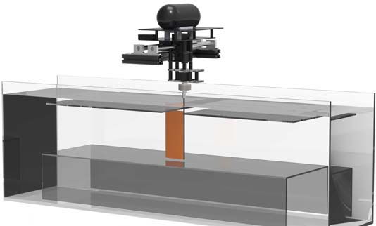
Downloaded from https://www.cambridge.org/core. Lehigh University, on 18 Jul 2019 at 13:16:21, subject to the Cambridge Core terms of use, available at https://www.cambridge.org/core/terms. https://doi.org/10.1017/jfm.2019.540
M. Kurt and others
(a) 2 k = 1.02 St = 0.13
(b) 1.02
-
L k = 1.02 St = 0.26
1 U k = 1.02 St = 0.39
k = 1.02 St = 0.51
k = 1.02 St = 0.63
CL 0 k 0.77
D*eq
U 1.00
-1
-
L 0.25
-2 0.52
0.5 1.0 1.5 2.0 2.5 0.2 0.4 0.6
D*eq D* St
F IGURE 2. Constrained foil experiments: (a) lift coefficient as a function of the
non-dimensional distance from the ground for k = 1.02 and (b) equilibrium altitude as a
function of the Strouhal number and reduced frequency. No data are shown in the regions
coloured with white.
for the constrained foil experiments. Figure 2(b) presents these equilibrium altitudes
as a function of the Strouhal number and reduced frequency. Indeed, the equilibrium
altitudes move farther from the ground as the Strouhal number increases for all of
the reduced frequencies examined. In contrast, the equilibrium altitudes move closer
to the ground as the reduced frequency increases.
The constrained foil experiments suggest that equilibrium altitudes exist for unsteady
ground effect swimmers, but they cannot prove whether or not dynamic recoil motions
of a freely swimming body alter the physics that give rise to these altitudes. To
prove the existence of equilibrium altitudes for freely swimming foils, we tested
foils that were free to move in the cross-stream direction. Figure 3 presents the
foil’s time-varying ground distance for St = 0.3 and various reduced frequencies
measured from the experiments and simulations. Regardless of the initial condition
and the reduced frequency, the foil reaches an equilibrium altitude in both the
experiments and the simulations. Moreover, the equilibrium altitudes measured from
the experiments and predicted by the simulations are in excellent agreement (Downloaded from https://www.cambridge.org/core. Lehigh University, on 18 Jul 2019 at 13:16:21, subject to the Cambridge Core terms of use, available at https://www.cambridge.org/core/terms. https://doi.org/10.1017/jfm.2019.540
Unsteady ground effect flow-mediated equilibrium altitudes
(a) (b)
0.75 0.75
D*eq = 0.41 D*eq = 0.38
D* 0.50 0.50
0.25 0.25
k=1 k=1
0.75 D*eq = 0.49 0.75 D*eq = 0.47
D* 0.50 0.50
0.25 0.25
k = 0.75 k = 0.75
0.75 0.75
D* 0.50 D*eq = 0.70
0.50
D*eq = 0.68
0.25 0.25
k = 0.5 k = 0.5
0 20 40 60 0 20 40 60
t/T t/T
Experimental Numerical
F IGURE 3. Time-varying ground distance as a function of time normalized by the period
of motion, T, for St = 0.3. Data from (a) experiments and (b) simulations. The line
colour from black to light grey represents three different initial conditions: D∗ = 0.25, 0.5
and 0.75. Three reduced frequency cases of k = 0.5, 0.75 and 1 are presented.
equilibrium altitudes are within 3 %–11 % of the experimental measurements for
all of the cases examined in figures 3 and 4. As the Strouhal number increases,
recoil oscillations increase and the equilibrium altitudes move further away from the
ground, in agreement with the constrained foil experiments (figure 2b). There is some
disagreement between the simulations and experiments in the initial time-varying
trajectories of the foil before an equilibrium altitude is reached. These discrepancies
can be attributed to the same viscous flow effects highlighted before – that is, mild
separation and/or end effects in the experiments that are not present in the simulations.
The potential flow simulations can be used to gain further insight into the energetic
performance of the foils at the equilibrium altitudes. Table 2 presents the thrust,
power, and propulsive efficiency for the unconstrained foils as compared to their
values far from the ground. In agreement with previous findings (Quinn et al.
2014b), near-ground altitudes lead to improvements in thrust production with no
penalty in efficiency. In fact, the thrust increases slightly more than the power
(4 %–17 % versus 3 %–15 %), causing the efficiency to increase slightly (1 %–2 %).
Freely swimming foils therefore automatically converge to altitudes where the same
875 R1-7Downloaded from https://www.cambridge.org/core. Lehigh University, on 18 Jul 2019 at 13:16:21, subject to the Cambridge Core terms of use, available at https://www.cambridge.org/core/terms. https://doi.org/10.1017/jfm.2019.540
M. Kurt and others
(a) (b)
0.75 0.75
D*eq = 0.80 D*eq = 0.83
D* 0.50 0.50
0.25 0.25
St = 0.5 St = 0.5
0.75 0.75
D* 0.50 0.50
D*eq = 0.62
0.25 0.25 D*eq = 0.55
St = 0.4 St = 0.4
0.75 0.75
D*eq = 0.41 D*eq = 0.38
D* 0.50 0.50
0.25 0.25
St = 0.3 St = 0.3
0 20 40 60 80 100 0 20 40 60 80 100
t/T t/T
Experimental Numerical
F IGURE 4. Time-varying ground distance as a function of normalized time for k = 1.
Data from (a) experiments and (b) simulations. The line colour from black to light grey
represents three different initial conditions: D∗ = 0.25, 0.5 and 0.75. Three Strouhal number
cases of St = 0.3, 0.4 and 0.5 are presented.
kinematics produce higher thrust. Regardless of St and k, the thrust improvement
was found to monotonically increase as the equilibrium altitude decreased (table 2).
However, the thrust improvements observed in the current study are smaller than those
of previous findings (Quinn et al. 2014b). This is likely due to the recoil oscillations
of the freely swimming foil in the current work. These lead to combined heaving
and pitching motions that are out of phase, producing poor thrust performance.
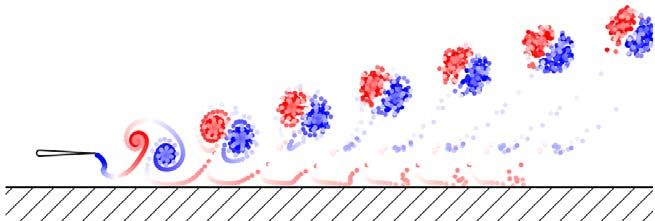
Figure 5 presents flow fields generated by the simulations for the corresponding
Strouhal number and reduced frequency cases. Regardless of the case examined, there
is a ubiquitous wake deflection, as observed in previous work, that has been linked
to inviscid vortex dynamics between the shed vortices and their images (Quinn et al.
2014b). It can also be observed that as the Strouhal number increases at constant
reduced frequency (k = 1), the vortex spacing increases in the cross-stream direction
as expected, since the amplitude of motion is increased. In contrast, as the reduced
frequency increases at a fixed Strouhal number (St = 0.3) the wake vortices are
compressed in the cross-stream and streamwise directions. This occurs since the
875 R1-8Downloaded from https://www.cambridge.org/core. Lehigh University, on 18 Jul 2019 at 13:16:21, subject to the Cambridge Core terms of use, available at https://www.cambridge.org/core/terms. https://doi.org/10.1017/jfm.2019.540
Unsteady ground effect flow-mediated equilibrium altitudes
(a) (b)
k=1 St = 0.5
k = 0.75 St = 0.4
k = 0.5 St = 0.3
F IGURE 5. Simulated wake structures at (a) St = 0.3 for varying reduced frequency and
(b) k = 1 for varying Strouhal number. Red and blue vortices represent counterclockwise
and clockwise rotations, respectively.
St k CT∗ CP∗ η∗ D∗eq,num
Case 0 0.2 0.5 1.12 1.11 1.01 0.48
Case 1 0.3 0.5 1.08 1.06 1.01 0.68
Case 2 0.3 0.75 1.13 1.11 1.02 0.47
Case 3 0.3 1.0 1.17 1.15 1.02 0.38
Case 4 0.4 1.0 1.10 1.08 1.02 0.55
Case 5 0.5 1.0 1.04 1.03 1.01 0.83
TABLE 2. Thrust and power coefficients, and efficiency for the unconstrained foil
simulations at steady-state equilibrium altitudes. The performance metrics are normalized
by the corresponding value for a foil operating far from the ground and denoted with a
superscript, (.)∗ . Note that the trajectories for Case 0 are not shown in figures 3 and 4.
amplitude and vortex wavelength are reduced as the reduced frequency increases for
a fixed Strouhal number and flow speed.
3.2. Physical mechanisms leading to stable equilibrium altitudes
We hypothesize that equilibrium altitudes arise from the balance among three effects
(figure 6a): a negative circulatory lift force due to a deflected jet mechanism, a
positive circulatory lift force due to a quasistatic mechanism, and a negative lift force
due to an added mass mechanism. To investigate this hypothesis, we performed
constrained pitching foil simulations with St = 0.3 and k = 1 over a range of
dimensionless ground proximities (0.22 6 D∗ 6 1). In the constrained foil simulations,
the equilibrium altitude occurs at D∗ = 0.47, which is further from the ground than
in the unconstrained simulations of Case 3 reported in table 2. This is due to the
difference in m∗ , where m∗ = 2.68 in the unconstrained simulations and m∗ = ∞
in the constrained simulations, leading to combined heaving and pitching motion in
875 R1-9Downloaded from https://www.cambridge.org/core. Lehigh University, on 18 Jul 2019 at 13:16:21, subject to the Cambridge Core terms of use, available at https://www.cambridge.org/core/terms. https://doi.org/10.1017/jfm.2019.540
M. Kurt and others
(a) r3 r2 r1 (b) 12
CL,cir
8 CL,add
CL,tot
4
1.0 CL,cir
CL,add CL 0
0.5
-4
- -8 D* = 0.7
CL 0
-12
-0.5
(c) 12
-1.0 CL,cir
8 CL,add
D*eq = 0.47
4
0.25 0.50 0.75 1.00
CL 0
D*
-4
(e) -8 D* = 0.46
-12
-deflect
CL,cir
(d) 12
r1 CL,cir
8 CL,add
4
-static
CL,cir
r2 CL 0
-4
- -8 D* = 0.22
CL,add
-12
r3 0 0.25 0.50 0.75 1.00
t/T
F IGURE 6. The decomposition of the lift force acting on a constrained pitching foil at
various ground proximities. White, grey and black lines denote the total lift, circulatory lift
and the added mass lift, respectively. (a) The cycle-averaged lift coefficient as a function
of dimensionless ground proximity. The equilibrium altitude is located at D∗eq = 0.47.
The time-varying lift over a cycle at (b) D∗ = 0.70, (c) D∗ = 0.46 and (d) D∗ = 0.22.
(e) Schematic of the physical origins of the dominant lift forces in three regions (R1 , R2
and R3 ).
the former and pure pitching motion in the latter. The boundary element simulations
are used to decompose the computed lift force into its circulatory and added mass
components. The instantaneous bound circulation of the foil is simply the negative of
the strength of the trailing-edge element – that is, Γbound = −µTE . The Kutta–Joukowski
theorem is then used to the compute the circulatory lift coefficient. The added mass
lift coefficient is the difference between the total lift coefficient and the circulatory
lift coefficient.
The time-varying circulatory and added mass lift coefficients are presented in
figure 6(b–d) for three ground proximities. Figure 6(b) shows a ground proximity
that is above its equilibrium altitude at D∗ = 0.7. The instantaneous added mass lift is
nearly symmetric about the origin, leading to zero lift in the time average. In contrast,
the magnitude of the trough in circulatory lift is slightly greater than the magnitude
of the peak in circulatory lift, leading to a negative lift force in the time average due
875 R1-10Downloaded from https://www.cambridge.org/core. Lehigh University, on 18 Jul 2019 at 13:16:21, subject to the Cambridge Core terms of use, available at https://www.cambridge.org/core/terms. https://doi.org/10.1017/jfm.2019.540
Unsteady ground effect flow-mediated equilibrium altitudes
to the deflected jet. Indeed, the time-averaged forces presented in figure 6(a) have a
negligible time-averaged added mass force and a negative time-averaged circulatory
force in the range 0.5 6 D∗ 6 1 in region R1 , which supports the hypothesis of the jet
deflection mechanism. Figure 6(c) shows a ground proximity that is slightly below the
equilibrium altitude at D∗ = 0.46. Both the instantaneous added mass and circulatory
lift seem to be symmetric, although in the time average (figure 6a) the circulatory and
added mass forces are slightly positive and negative, respectively. This highlights the
fact that, in general, all three mechanisms balance to define an equilibrium altitude.
However, below the equilibrium altitude in region R2 the time-averaged quasistatic
circulatory force dominates the mechanisms, leading to a net positive lift force in
the range 0.22 6 D∗ 6 0.5 (figure 6a). Figure 6(d) presents a ground proximity well
below the equilibrium altitude at D∗ = 0.22. Here the asymmetry in the added mass
lift is clear, both in a difference in the magnitudes of the peak and trough and in the
waveform of the signal, which leads to a time-averaged negative lift as hypothesized.
The difference in the magnitude of the peak and trough of the circulatory force is
also clear, highlighting the hypothesized quasistatic mechanism. Based on the rate
of change of the time-averaged circulatory and added mass forces as a D∗ = 0.22 is
approached (figure 6a), we postulate that the negative added mass force will dominate
the mechanisms for D∗ < 0.22, leading to a net negative lift force in region R3 and an
unstable equilibrium altitude between regions R2 and R3 . Future work will examine
this in more detail.
For all of the cases examined in this study, a deflected vortex wake has been
observed, which in the time average forms a deflected jet away from the ground.
When the foil is sufficiently far from the ground, one can imagine performing a
control volume analysis on the time-averaged flow field to determine the net lift force.
The sides of a rectangular control volume that are normal to the cross-stream direction
can extend far enough from the foil such that the pressure on those boundaries would
be of equal magnitude and act in opposite directions, leading to no net pressure force.
The lift force would then solely arise from the rate of change of momentum due to
the deflected jet, and it would act towards the ground (R1 in figure 6e). Given the
ubiquitous deflected jet, it is expected that this negative lift force occurs at all of the
ground proximities examined, and it can be understood as an unsteady circulatory
force. The deflected jet disappears as the wake strength disappears with decreasing
reduced frequency and as the foil is moved far from the ground. It is expected that
the magnitude of the negative lift force from the deflected jet would then scale with
increasing k and inversely with D∗ .
At moderate ground proximities, the control volume’s lower boundary must coincide
with the ground plane in order to be as far from the foil as possible without additional
ground reaction forces arising from the control volume cutting through the ground
itself. However, at moderate distances from the ground, the pressure on the ground
will not be at the free-stream pressure, and a net pressure force acting on the control
volume away from the ground (pressure elevated above the free stream on the ground)
will arise. Fundamentally, this will give rise to a net positive bound circulation in
the time average. This can be further understood as a quasistatic circulatory force,
also known as the classical steady ground effect. When the foil reaches the bottom
of its downstroke, it will be closer to the ground than when it reaches the top of
its upstroke, leading to a greater enhancement of the bound circulation at the closest
proximity position and a time-averaged positive lift force (R2 in figure 6e). Since the
magnitude of this force depends on the difference in bound circulation enhancement
at the foil’s extreme positions, it is expected that this quasistatic force will increase
with increasing amplitude of motion.
875 R1-11Downloaded from https://www.cambridge.org/core. Lehigh University, on 18 Jul 2019 at 13:16:21, subject to the Cambridge Core terms of use, available at https://www.cambridge.org/core/terms. https://doi.org/10.1017/jfm.2019.540
M. Kurt and others
At close ground proximities, a time-averaged added mass lift force arises that cannot
be understood through a steady control volume analysis. Classic theory describes that
the added mass of a cylinder near a ground plane should increase inversely with the
dimensionless ground proximity squared (Keulegan 1958; Brennen 1982). Therefore,
when the foil reaches the bottom of its downstroke its added mass will be amplified
more than when the foil is at the top of its upstroke. At the bottom of its downstroke,
the foil experiences a negative added mass lift force, which would then be larger
in magnitude than the positive added mass lift force experienced at the top of its
upstroke. This imbalance will lead to a negative time-averaged added mass lift force
(R3 in figure 6e). Since the magnitude of this force also depends on the difference
in the extreme positions, it is expected that it will increase with increasing amplitude
of motion.
Now the mechanisms behind the observed trends in the equilibrium altitude with
variations in St and k can be postulated. In the current study, St is increased by
increasing the amplitude of motion. This should increase the magnitude of the
quasistatic circulatory force and the added mass force, thereby pushing the equilibrium
altitude (the boundary between regions R1 and R2 ) further from the ground. When
the reduced frequency is increased, the magnitude of the jet deflection force should
increase, thereby pushing the equilibrium altitude closer to the ground. Alternatively,
when the reduced frequency is increased the amplitude of motion is also decreased,
which consequently will weaken the quasistatic and added mass forces, thereby
moving the equilibrium closer to the ground as well.
4. Conclusions
For the first time, it is experimentally confirmed that freely swimming pitching foils
converge to stable equilibrium altitudes. When the foils are within approximately 1–3
chord lengths of the ground, negative lift forces pull them towards the ground; when
the foils are closer than approximately 1 chord to the ground, positive lift forces
push them away from the ground. These equilibrium altitudes are insensitive to initial
altitude. Furthermore, the equilibria are dependent on swimming kinematics: in both
constrained and unconstrained cases, equilibrium altitudes increase with increasing
Strouhal number and decreasing reduced frequency. Despite viscous boundary layers
on the foil and the ground in the experiments, there is excellent agreement between
the potential flow simulations and the experiments for all of the cases considered
(3 %–11 % difference). This suggests that the equilibrium altitudes are primarily
an inviscid phenomenon. The physical mechanisms leading to stable equilibrium
altitudes were identified as an interplay among three time-averaged forces: a negative
jet deflection circulatory force, a positive quasistatic circulatory force and a negative
added mass force.
The existence of equilibrium altitudes has significant implications for near-ground
swimming. Swimming outside of equilibrium could incur an energetic penalty, because
doing so would require asymmetric motions to counteract near-ground lift forces.
Over the range of conditions considered, swimming at equilibrium led to higher
thrusts and efficiencies (4 %–17 % and 1 %–2 % higher than far from the ground,
respectively). However, thrust increases as high as 44 % have been observed closer
to the ground (D∗ = 0.38; Quinn et al. 2014b), so there may be cases where it is
worth the incurred energy cost to actively maintain an altitude beneath equilibrium.
Efficient near-ground swimming would therefore benefit from predictive models of
near-ground equilibria. Given that equilibria exist even in inviscid simulations, adapted
875 R1-12Downloaded from https://www.cambridge.org/core. Lehigh University, on 18 Jul 2019 at 13:16:21, subject to the Cambridge Core terms of use, available at https://www.cambridge.org/core/terms. https://doi.org/10.1017/jfm.2019.540
Unsteady ground effect flow-mediated equilibrium altitudes
added mass and circulatory scalings may be sufficient to model the Strouhal number
and reduced frequency dependence observed here. Exploring these equilibria would
provide further insight into the behaviour, control and energetics of flatfishes, rays
and other near-ground fish or fish-inspired robots.
Acknowledgements
This work was supported by the Office of Naval Research under Program Director
Dr R. Brizzolara on MURI grant number N00014-08-1-0642 and BAA grant number
N00014-18-1-2537, as well as by the National Science Foundation under Program
Director Dr R. Joslin in Fluid Dynamics within CBET on NSF CAREER award
number 1653181 and NSF collaboration award number 1921809.
References
B LAKE , R. W. 1983 Mechanics of gliding in birds with special reference to the influence of the
ground effect. J. Biomech. 16 (8), 649–654.
B LEVINS , E. & L AUDER , G. V. 2013 Swimming near the substrate: a simple robotic model of
stingray locomotion. Bioinspir. Biomim. 8 (1), 016005.
B RENNEN , C. E. 1982 A review of added mass and fluid inertial forces. Tech. Rep. CR 82.010.
Naval Civil Engineering Laboratory.
C UI , E. & Z HANG , X. 2010 Ground effect aerodynamics. In Encyclopedia of Aerospace Engineering.
American Cancer Society.
DAI , L., H E , G. & Z HANG , X. 2016 Self-propelled swimming of a flexible plunging foil near a
solid wall. Bioinspir. Biomim. 11 (4), 046005.
F ERNÁNDEZ -P RATS , R., R ASPA , V., T HIRIA , B., H UERA -H UARTE , F. & G ODOY-D IANA , R. 2015
Large-amplitude undulatory swimming near a wall. Bioinspir. Biomim. 10 (1), 016003.
G ODOY-D IANA , R., A IDER , J.-L. & W ESFREID , J. E. 2008 Transitions in the wake of a flapping
foil. Phys. Rev. E 77 (1), 016308.
H AINSWORTH , F. R. 1988 Induced drag savings from ground effect and formation flight in brown
pelicans. J. Expl Biol. 135 (1), 431–444.
I OSILEVSKII , G. 2008 Asymptotic theory of an oscillating wing section in weak ground effect. Eur. J.
Mech. (B/Fluids) 27 (4), 477–490.
K ATZ , J. & P LOTKIN , A. 2001 Low-speed Aerodynamics, vol. 13. Cambridge University Press.
K EULEGAN , G. H. 1958 Forces on cylinders and plates in an oscillating fluid. J. Res. Natl Bur.
Stand. 2857, 423–440.
K IM , B., PARK , S. G., H UANG , W.-X. & S UNG , H. J. 2017 An autonomous flexible propulsor in a
quiescent flow. Intl J. Heat Fluid Flow 68, 151–157.
K RASNY, R. 1986 Desingularization of periodic vortex sheet roll-up. J. Comput. Phys. 65, 292–313.
M IVEHCHI , A., DAHL , J. & L ICHT, S. 2016 Heaving and pitching oscillating foil propulsion in
ground effect. J. Fluids Struct. 63, 174–187.
M OORED , K. W. 2018 Unsteady three-dimensional boundary element method for self-propelled
bio-inspired locomotion. Comput. Fluids 167, 324–340.
M OORED , K. W. & Q UINN , D. B. 2018 Inviscid scaling laws of a self-propelled pitching airfoil.
AIAA J. 0 (0), 1–15.
N OWROOZI , B. N., S TROTHER , J. A., H ORTON , J. M., S UMMERS , A. P. & B RAINERD , E. L. 2009
Whole-body lift and ground effect during pectoral fin locomotion in the northern spearnose
poacher (Agonopsis vulsa). Zoology 112 (5), 393–402.
PAN , Y., D ONG , X., Z HU , Q. & Y UE , D. K. P. 2012 Boundary-element method for the prediction
of performance of flapping foils with leading-edge separation. J. Fluid Mech. 698, 446–467.
PARK , H. & C HOI , H. 2010 Aerodynamic characteristics of flying fish in gliding flight. J. Expl Biol.
213 (19), 3269–3279.
PARK , S. G., K IM , B. & S UNG , H. J. 2017 Hydrodynamics of a self-propelled flexible fin near the
ground. Phys. Fluids 29 (5), 051902.
875 R1-13Downloaded from https://www.cambridge.org/core. Lehigh University, on 18 Jul 2019 at 13:16:21, subject to the Cambridge Core terms of use, available at https://www.cambridge.org/core/terms. https://doi.org/10.1017/jfm.2019.540
M. Kurt and others
P ERKINS , M., E LLES , D., BADLISSI , G., M IVEHCHI , A., DAHL , J. & L ICHT, S. 2018 Rolling and
pitching oscillating foil propulsion in ground effect. Bioinspir. Biomim. 13, 016003.
Q UINN , D. B., L AUDER , G. V. & S MITS , A. J. 2014a Flexible propulsors in ground effect. Bioinspir.
Biomim. 9 (3), 036008.
Q UINN , D. B., M OORED , K. W., D EWEY, P. A. & S MITS , A. J. 2014b Unsteady propulsion near a
solid boundary. J. Fluid Mech. 742, 152–170.
R AYNER , J. M. V. 1991 On the aerodynamics of animal flight in ground effect. Phil. Trans. R. Soc.
Lond. B 334 (1269), 119–128.
ROZHDESTVENSKY, K. V. 2006 Wing-in-ground effect vehicles. Prog. Aerosp. Sci. 42 (3), 211–283.
TANIDA , Y. 2001 Ground effect in flight. JSME Intl J. Ser. B Fluids Therm. Engng 44 (4), 481–486.
VAN T RUONG , T., B YUN , D., K IM , M. J., Y OON , K. J. & PARK , H. C. 2013a Aerodynamic forces
and flow structures of the leading edge vortex on a flapping wing considering ground effect.
Bioinspir. Biomim. 8 (3), 036007.
VAN T RUONG , T., K IM , J., K IM , M. J., PARK , H. C., Y OON , K. J. & B YUN , D. 2013b Flow
structures around a flapping wing considering ground effect. Exp. Fluids 54 (7), 1575.
W EBB , P. W. 1993 The effect of solid and porous channel walls on steady swimming of steelhead
trout Oncorhynchus mykiss. J. Expl Biol. 178 (1), 97–108.
W EBB , P. W. 2002 Kinematics of plaice, Pleuronectes platessa, and cod, Gadus morhua, swimming
near the bottom. J. Expl Biol. 205 (14), 2125–2134.
W IE , S. Y., L EE , S. & L EE , D. J. 2009 Potential panel and time-marching free-wake-coupling
analysis for helicopter rotor. J. Aircraft 46 (3), 1030–1041.
W ILLIS , D. J. 2006 An unsteady, accelerated, high order panel method with vortex particle wakes.
PhD thesis, Massachusetts Institute of Technology.
Z HANG , C., H UANG , H. & L U , X.-Y. 2017 Free locomotion of a flexible plate near the ground.
Phys. Fluids 29 (4), 041903.
875 R1-14You can also read