T2P9D01 Mainboard User's Guide - For System Configuration and Set Up - Raptor Computing Systems Wiki
←
→
Page content transcription
If your browser does not render page correctly, please read the page content below
T2P9D01 Mainboard

                                                                       User's Guide
                                                            For System Configuration
                                                                        and Set Up

© 2017 - 2018 Raptor Computing Systems, LLC            T2P9D01 User's Guide Version 1.06
All Rights Reserved                                             https://www.raptorcs.com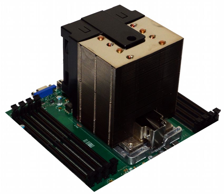
Table of Contents
COPYRIGHT AND DISCLAIMERS............................................................................................5

SAFETY INFORMATION............................................................................................................6
Electrical Safety.................................................................................................................................................... 6

Operational Safety................................................................................................................................................ 6

NOTICES....................................................................................................................................7
Federal Communications Commission Statement............................................................................................ 7

Environmental Disposal Statements................................................................................................................... 7

MAINBOARD SPECIFICATIONS – STANDARD......................................................................8

MAINBOARD SPECIFICATIONS – LITE.................................................................................10

MAINBOARD OVERVIEW.......................................................................................................12
Design.................................................................................................................................................................. 12

Installation........................................................................................................................................................... 13

Removal............................................................................................................................................................... 13

CPU INSTALLATION AND REMOVAL....................................................................................14
Background......................................................................................................................................................... 14

Installation........................................................................................................................................................... 15

Removal............................................................................................................................................................... 17

RAM INSTALLATION AND REMOVAL...................................................................................18
Population Tables – Standard............................................................................................................................ 18

Population Tables – Lite..................................................................................................................................... 19

Installation........................................................................................................................................................... 20

Removal............................................................................................................................................................... 20

HEADERS AND CONNECTORS.............................................................................................21

© 2017 - 2018 Raptor Computing Systems, LLC                                                                     T2P9D01 User's Guide Version 1.06
All Rights Reserved                                                                                                      https://www.raptorcs.com
                                                                                    2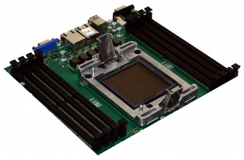
Pin Numbering Conventions............................................................................................................................. 21

Front Panel – All Variants................................................................................................................................... 22

BMC Serial Console – All Variants.................................................................................................................... 24

Trusted Platform Module Connector – All Variants......................................................................................... 25

FlexVer™ Connector – All Variants................................................................................................................... 27

OCC Mode – All Variants.................................................................................................................................... 29

BMC External Reset Header – All Variants....................................................................................................... 30

BMC TTL Auxiliary Serial Header – All Variants............................................................................................... 31

BMC Heartbeat Indicator Header – All Variants...............................................................................................32

Internal USB 3.0 Header – All Variants.............................................................................................................. 33

BMC I2C Port 5 – All Variants............................................................................................................................ 35

BMC I2C Port 6 – All Variants............................................................................................................................ 36

Planar VPD Programming Header – All Variants..............................................................................................37

FPGA Programming Header – All Variants....................................................................................................... 38

FPGA Mode Switch 1 – All Variants................................................................................................................... 39

Chassis Intrusion Detect – All Variants............................................................................................................ 40

On-Board VGA Disable Jumper – All Variants.................................................................................................. 41

Disk Drive Activity Indicator – All Variants....................................................................................................... 42

PM8068 SAS Debug Connector – SAS Variants Only......................................................................................43

5V Power – SAS Variants Only.......................................................................................................................... 45

CPU 1 Secure Mode Disable – All Variants....................................................................................................... 46

CPU 2 Secure Mode Disable – Standard Variants Only...................................................................................47

PMBus Connector – All Variants....................................................................................................................... 48

CPU EPS Power Connectors – All Variants...................................................................................................... 49

ATX Power Connector – All Variants................................................................................................................. 50

CPU 1 PCI Express Slots – All Variants............................................................................................................ 52

CPU 2 PCI Express Slots – Standard Variants Only........................................................................................ 56

CPU 2 Micro PCIe Connector – Standard Variants Only.................................................................................60

© 2017 - 2018 Raptor Computing Systems, LLC                                                              T2P9D01 User's Guide Version 1.06
All Rights Reserved                                                                                               https://www.raptorcs.com
                                                                              3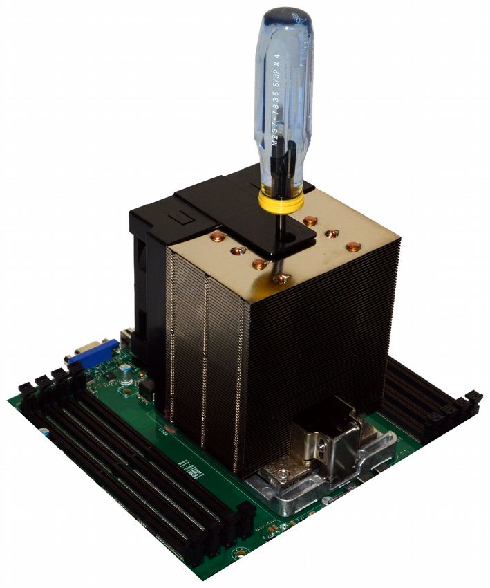
CPU 1 Fan Header – All Variants....................................................................................................................... 62

CPU 2 Fan Header – All Variants....................................................................................................................... 63

Primary Chassis Fan Headers – All Variants.................................................................................................... 64

Secondary Chassis Fan Header – All Variants.................................................................................................65

FAN ZONES..............................................................................................................................66
Connections........................................................................................................................................................ 66

Algorithm Description........................................................................................................................................ 66

USAGE......................................................................................................................................67
Initial Power-On.................................................................................................................................................. 67

Selecting a Boot Medium................................................................................................................................... 67

BMC Access........................................................................................................................................................ 68

Host Firmware Updates...................................................................................................................................... 68

BMC Firmware Updates..................................................................................................................................... 68

EARLY BOOT DEVICE FIRMWARE........................................................................................70
Introduction......................................................................................................................................................... 70

Installation........................................................................................................................................................... 70

Removal............................................................................................................................................................... 70

SUPPORT.................................................................................................................................72
Getting Help........................................................................................................................................................ 72

ERRATA....................................................................................................................................73
PCB Version 1.00................................................................................................................................................ 73

PCB Version 1.01................................................................................................................................................ 73

© 2017 - 2018 Raptor Computing Systems, LLC                                                                    T2P9D01 User's Guide Version 1.06
All Rights Reserved                                                                                                     https://www.raptorcs.com
                                                                                   4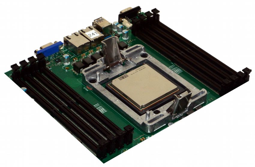
Copyright and Disclaimers

Copyright © 2017 – 2018 Raptor Computing Systems, LLC. All Rights Reserved.

Product warranty or service will not be extended if: (1) the product is damaged by the consumer in any
way, including any alterations that affect the operability of the feature or features being claimed under
warranty and/or product service; or (2) the serial number of the product is defaced or missing.

RAPTOR COMPUTING SYSTEMS, LLC PROVIDES THIS MANUAL “AS IS” WITHOUT WARRANTY
OF ANY KIND, EITHER EXPRESS OR IMPLIED, INCLUDING BUT NOT LIMITED TO THE IMPLIED
WARRANTIES OR CONDITIONS OF MERCHANTABILITY OR FITNESS FOR A PARTICULAR
PURPOSE. IN NO EVENT SHALL RAPTOR COMPUTING SYSTEMS, LLC, ITS DIRECTORS,
OFFICERS, MEMBERS, MANAGERS, EMPLOYEES OR AGENTS BE LIABLE FOR ANY INDIRECT,
SPECIAL, INCIDENTAL, OR CONSEQUENTIAL DAMAGES (INCLUDING DAMAGES FOR LOSS OF
PROFITS, LOSS OF BUSINESS, LOSS OF USE OR DATA, INTERRUPTION OF BUSINESS AND
THE LIKE), EVEN IF RAPTOR COMPUTING SYSTEMS, LLC HAS BEEN ADVISED OF THE
POSSIBILITY OF SUCH DAMAGES ARISING FROM ANY DEFECT OR ERROR IN THIS MANUAL
OR PRODUCT.

SPECIFICATIONS AND INFORMATION CONTAINED IN THIS MANUAL ARE FURNISHED FOR
INFORMATIONAL USE ONLY, AND ARE SUBJECT TO CHANGE AT ANY TIME WITHOUT NOTICE,
AND SHOULD NOT BE CONSTRUED AS A COMMITMENT BY RAPTOR COMPUTING SYSTEMS,
LLC. RAPTOR COMPUTING SYSTEMS, LLC ASSUMES NO RESPONSIBILITY OR LIABILITY FOR
ANY ERRORS OR INACCURACIES THAT MAY APPEAR IN THIS MANUAL, INCLUDING THE
PRODUCTS AND SOFTWARE DESCRIBED IN IT.

Products and corporate names appearing in this manual may or may not be registered trademarks or
copyrights of their respective companies, and are used only for identification or explanation and to the
owners’ benefit, without intent to infringe.

© 2017 - 2018 Raptor Computing Systems, LLC                          T2P9D01 User's Guide Version 1.06
All Rights Reserved                                                           https://www.raptorcs.com
                                                   5
Safety Information
ELECTRICAL SAFETY

• To reduce the risk of electric shock, disconnect the power cable before relocating or servicing the
  system.

• When adding or removing devices to or from the system, ensure that the power cables for the
  devices are unplugged before the signal cables are connected. If possible, disconnect all power
  cables from the existing system before you add a device.

• Before connecting or removing signal cables from the motherboard, ensure that all power cables are
  unplugged.

• Seek professional assistance before using an adapter or extension cord. These devices could
  interrupt the grounding circuit.

• Make sure that your power supply is set to the correct voltage in your area. If you are not sure about
  the voltage of the electrical outlet you are using, contact your local power company.

• If your power supply is not functioning, do not attempt to repair it. Contact a qualified service
   technician or your retailer.

OPERATIONAL SAFETY

• Before installing the motherboard or connecting devices to it, carefully read any and all provided
  manuals for the devices in question.

• Before using the product, make sure all cables are correctly connected and the power cables are
  not damaged. If you find any damage, contact your dealer immediately.

• To avoid short circuits, keep paper clips, screws, staples, and other foreign metallic objects away
  from connectors, slots, sockets and circuitry.

• Avoid dust, humidity, and temperature extremes. Do not locate the product in any area where it may
  become wet or damp.

• Place the product on a stable surface at all times.

• If you encounter technical problems with the product, contact a qualified service technician or your
   retailer.

© 2017 - 2018 Raptor Computing Systems, LLC                           T2P9D01 User's Guide Version 1.06
All Rights Reserved                                                            https://www.raptorcs.com
                                                     6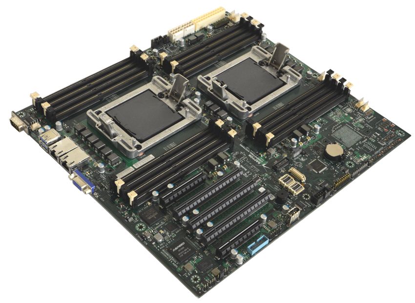
Notices
FEDERAL COMMUNICATIONS COMMISSION STATEMENT

This device complies with Part 15 of the FCC Rules. Operation is subject to the
following two conditions:
• This device may not cause harmful interference, and
• This device must accept any interference received including interference that
    may cause undesired operation.

This equipment has been tested and found to comply with the limits for a Class
B digital device, pursuant to Part 15 of the FCC Rules. These limits are designed
to provide reasonable protection against harmful interference in a residential
installation. This equipment generates, uses and can radiate radio frequency energy
and, if not installed and used in accordance with manufacturer’s instructions, may
cause harmful interference to radio communications. However, there is no guarantee
that interference will not occur in a particular installation. If this equipment does
cause harmful interference to radio or television reception, which can be determined
by turning the equipment off and on, the user is encouraged to try to correct the
interference by one or more of the following measures:

•   Reorient or relocate the receiving antenna.
•   Increase the separation between the equipment and receiver.
•   Connect the equipment to an outlet on a circuit different from that to which the
    receiver is connected.
•   Consult the dealer or an experienced radio/TV technician for help.

ENVIRONMENTAL DISPOSAL STATEMENTS

               DO NOT throw the motherboard in municipal waste. This product has been designed to
               enable proper reuse of parts and recycling. This symbol of the crossed out wheeled bin
               indicates that the product (electrical and electronic equipment) should not be placed in
               municipal waste. Check local regulations for disposal of electronic products.

              DO NOT throw the mercury-containing button cell battery in municipal waste. This
              symbol of the crossed out wheeled bin indicates that the battery should not be
              placed in municipal waste.

© 2017 - 2018 Raptor Computing Systems, LLC                          T2P9D01 User's Guide Version 1.06
All Rights Reserved                                                           https://www.raptorcs.com
                                                    7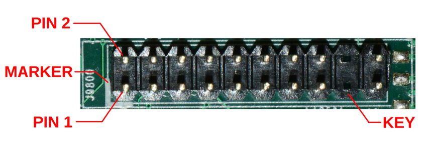
Mainboard Specifications – Standard
Processor                                     2x IBM POWER9 “Sforza” Socket (LGA 2601)
                                              4 - 24 core IBM POWER9 Processors
                                              High speed XBUS interconnect
Core Logic                                    Direct Attach PCIe
Form Factor                                   EATX, 12” x 13”
System Features      Fan Control              Y
                     Nominal Fan Zones        3
                     Fan Connectors           7
                     Fan Control Driver       MAX31785 / AST2500
                     Rack Ready               Y
                     Front Panel Header       SuperMicro Compatible
                     TPM Header               LPC / I2C
                     SMBus Header             Y
                     BMC                      Y
                     BMC Type                 OpenBMC Compatible (AST2500)
                     FlexVer™ Ready           Y
Memory               Total Slots              16 (4 channels per CPU)
                     Capacity                 2TB maximum
                     Memory Type              DDR4 1600/1866/2133/2400/2666
                     Memory Features          ECC
                     Module Sizes             8GB, 16GB, 32GB, 64GB, 128GB (RDIMM)
Expansion Slots      Total PCIe Slots         5
                     Total µPCIe Ports        1
                     PCIe Generation          1,2,3,4
                     CAPI 2 Capable Slots 3 x16 slots
Storage              Microsemi PM8068         4 SAS (iPASS+)
                     (optional)
                                              4 SAS/SATA
Networking           Broadcom BCM5719         2 host GbE
                                              NCSI-SI BMC link
Graphics             AST2500                  VGA
USB                  TI TUSB7430              2x USB3.0 ports on rear panel
                                              2x USB3.0 ports on internal header
Serial               Host                     1x RS232 port on rear panel

© 2017 - 2018 Raptor Computing Systems, LLC                        T2P9D01 User's Guide Version 1.06
All Rights Reserved                                                         https://www.raptorcs.com
                                                  8
BMC 1x RS232 port on internal header
1x TTL port on internal header
Environmental Requirements Operation: 10°C - 35°C
Storage: -40°C - 70°C
Humidity: 20% - 90%, non-condensing
NOTE: Specifications are subject to change without notice.
© 2017 - 2018 Raptor Computing Systems, LLC T2P9D01 User's Guide Version 1.06
All Rights Reserved https://www.raptorcs.com
9Mainboard Specifications – Lite
Processor 1x IBM POWER9 “Sforza” Socket (LGA 2601)
4 - 24 core IBM POWER9 Processors
Core Logic Direct Attach PCIe
Form Factor EATX, 12” x 13”
System Features Fan Control Y
Nominal Fan Zones 3
Fan Connectors 7
Fan Control Driver MAX31785 / AST2500
Rack Ready Y
Front Panel Header SuperMicro Compatible
TPM Header LPC / I2C
SMBus Header Y
BMC Y
BMC Type OpenBMC Compatible (AST2500)
FlexVer™ Ready Y
Memory Total Slots 8 (4 channels per CPU)
Capacity 1TB maximum
Memory Type DDR4 1600/1866/2133/2400/2666
Memory Features ECC
Module Sizes 8GB, 16GB, 32GB, 64GB, 128GB (RDIMM)
Expansion Slots Total PCIe Slots 2
Total µPCIe Ports 0
PCIe Generation 1,2,3,4
CAPI 2 Capable Slots 1 x16 slot
Storage Microsemi PM8068 4 SAS (iPASS+)
(optional) 4 SAS/SATA
Networking Broadcom BCM5719 2 host GbE
NCSI-SI BMC link
Graphics AST2500 VGA
USB TI TUSB7430 2x USB3.0 ports on rear panel
2x USB3.0 ports on internal header
Serial Host 1x RS232 port on rear panel
BMC 1x RS232 port on internal header
© 2017 - 2018 Raptor Computing Systems, LLC T2P9D01 User's Guide Version 1.06
All Rights Reserved https://www.raptorcs.com
101x TTL port on internal header
Environmental Requirements Operation: 10°C - 35°C
Storage: -40°C - 70°C
Humidity: 20% - 90%, non-condensing
NOTE: Specifications are subject to change without notice.
© 2017 - 2018 Raptor Computing Systems, LLC T2P9D01 User's Guide Version 1.06
All Rights Reserved https://www.raptorcs.com
11Mainboard Overview
DESIGN
The T2P9D01 has been specifically designed for applications requiring high security, high I/O
capability, and large amounts of processing capability. PCIe slots and peripherals are directly
connected to each CPU, therefore two CPUs must be installed to use all PCIe slots.
Illustration 1: TL2P9D01 Standard Edition Block Diagram
© 2017 - 2018 Raptor Computing Systems, LLC T2P9D01 User's Guide Version 1.06
All Rights Reserved https://www.raptorcs.com
12INSTALLATION
NOTE: Before you install this mainboard into your chassis, study the pattern of mounting studs, rear
panel slots, and internal chassis components to ensure the mainboard fits correctly. There are 10
mounting holes available on the T2P9D01; ensure that your chassis provides studs for all 10 for
maximum reliability and longevity of the mainboard.
NOTE: Installation of the mainboard should take place in a static-controlled environment using
appropriate anti-static measures. Failure to follow these precautions could result in permanent
damage to the mainboard and attached components.
Begin installation by examining your chassis. If there is an existing I/O shield in your chassis, remove
it by gently striking it from the outside of your chassis; it should pop free. Align the new I/O shield
inside your chassis so that the ridges on the I/O shield point away from the interior of your chassis;
then, gently but firmly snap the new I/O shield into place in the rear of your chassis.
Carefully place the mainboard inside the chassis, ensuring that the I/O ports are aligned with the
corresponding holes in the I/O shield. Gently press the mainboard into the I/O shield until the
mounting holes are aligned with the chassis studs. Secure the mainboard with one screw in the lower
right corner, followed by one in the upper left corner, then install the remaining screws. Torque all
mainboard mounting screws to 7 ft-lbs (0.8N-m).
WARNING: There are fragile electronic components located on the entire bottom surface of the
mainboard, including near the mainboard mounting holes. Ensure that the mainboard is aligned with
the studs before allowing any part of the rear surface to contact the mounting studs; also ensure that
the mainboard does not slide on the studs once positioned. Failure to follow these instructions could
result in severe damage to the mainboard. If you believe you have damaged one or more parts on the
bottom of the mainboard, but have not yet applied power, stop and remove the mainboard without
applying power. Inspect the mainboard for mechanical damage, and if present return the mainboard
for repair service.
REMOVAL
Begin by moving the chassis to a static-controlled environment. Before removing the mainboard,
remove all attached cables, peripherals, and RAM. Ensure that both CPUs and heatsinks have been
removed, and that both protective socket covers are in place. Carefully loosen and remove all screws,
saving the lower right hand corner for last. Gently lift the side of the mainboard farthest from the I/O
shield, then slide the ports out of the I/O shield. Do not allow the mainboard to fall onto or contact the
chassis mounting studs at this point. Carefully remove the mainboard from the chassis. If the
mainboard is to be returned for service, immediately place it in an appropriately sized anti-static bag.
© 2017 - 2018 Raptor Computing Systems, LLC T2P9D01 User's Guide Version 1.06
All Rights Reserved https://www.raptorcs.com
13CPU Installation and Removal
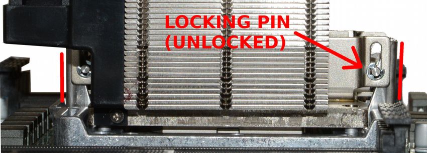
BACKGROUND
The POWER9 CPU uses a unique retention mechanism designed to center-load the CPU in the
socket and ensure good contact in the area of the central lands. This mechanism is spring loaded; a
single 5/32” hex screw engages and disengages the retention system.
The heatsink assemblies you have received may have had the screw tighten or loosen in transit. After
placing the heatsink on the CPU per the following instructions, visually inspect the two latching prongs
protruding from the load frame assembly. If these prongs are not vertical, loosen the retention screw
of the heatsink assembly and gently reposition the heatsink, watching for the latching prongs to move
into a vertical position.
Illustration 2: Correct Retention Mechanism Prong Alignment (Unlocked)
NOTE: Incorrectly positioned locking pins will cause the heatsink to start to tilt as the retention screw
is tightened. If this happens, immediately stop tightening the screw, carefully loosen the retention
screw, and double-check the prong and pin alignment before attempting to reattach the heatsink. In
some cases, removing and re-placing the heatsink is the easiest method to allow it to seat correctly.
© 2017 - 2018 Raptor Computing Systems, LLC T2P9D01 User's Guide Version 1.06
All Rights Reserved https://www.raptorcs.com
14INSTALLATION
WARNING: Both the CPUs and the mainboard are static sensitive. Installation and removal of either
CPU must take place in an appropriate anti-static environment.
Illustration 3: Socket as Shipped
Carefully remove the protective cover, making sure not to touch any of the exposed socket pins.
Illustration 4: Remove Protective Cover
© 2017 - 2018 Raptor Computing Systems, LLC T2P9D01 User's Guide Version 1.06
All Rights Reserved https://www.raptorcs.com
15Align the notches of the CPU with the protrusions on the socket, then carefully place the CPU in the
socket. If no indium pad is present on the bottom of the heatsink assembly, carefully center an indium
pad on top of the CPU.
Illustration 5: Align Notches and Carefully Place CPU in Socket
Place the heatsink assembly on top of the CPU, following instructions given earlier.
Illustration 6: Align Pins and Place Heatsink on CPU
© 2017 - 2018 Raptor Computing Systems, LLC T2P9D01 User's Guide Version 1.06
All Rights Reserved https://www.raptorcs.com
16Using a 5/32” hex driver fully inserted into the retention mechanism screw, tighten the retention
mechanism screw by turning the driver clockwise until a hard stop has been reached.
Illustration 7: Tighten Retention Scew until Hard Stop
Your CPU now is correctly installed. If you have a second CPU, repeat this process for the other
socket.
REMOVAL
Removal of the heatsink and CPU follows the installation procedure given above, only in reverse.
Start with step 5, turning the hex driver counterclockwise, and end with step 1, replacing the socket
protective cover into postion over the socket.
WARNING: Before attempting to remove the heatsink, ensure the mainboard has been placed
horizontal to the ground. Failing to do so could cause the CPU to fall out of the socket, causing
damage to the CPU, the CPU socket, and any components located below the CPU.
© 2017 - 2018 Raptor Computing Systems, LLC T2P9D01 User's Guide Version 1.06
All Rights Reserved https://www.raptorcs.com
17RAM Installation and Removal
POPULATION TABLES – STANDARD
Quantity Slot Population
Processor 1 Processor 2
A1 B1 C1 D1 A2 B2 C2 D2 A1 B1 C1 D1 A2 B2 C2 D2
1 DIMM X
2 DIMMs X X
3 DIMMs X X X
4 DIMMs X X X X
Processor Not Installed
5 DIMMs X X X X X
6 DIMMs X X X X X X
7 DIMMs X X X X X X X
8 DIMMs X X X X X X X X
1 DIMM X
2 DIMMs X X
3 DIMMs X X X
4 DIMMs X X X X
5 DIMMs X X X X X
6 DIMMs X X X X X X
7 DIMMs X X X X X X X
8 DIMMs X X X X X X X X
9 DIMMs X X X X X X X X X
10 DIMMs X X X X X X X X X X
11 DIMMs X X X X X X X X X X X
12 DIMMs X X X X X X X X X X X X
13 DIMMs X X X X X X X X X X X X X
14 DIMMs X X X X X X X X X X X X X X
15 DIMMs X X X X X X X X X X X X X X X
16 DIMMs X X X X X X X X X X X X X X X X
(X) denotes memory DIMM is installed in indicated slot
© 2017 - 2018 Raptor Computing Systems, LLC T2P9D01 User's Guide Version 1.06
All Rights Reserved https://www.raptorcs.com
18POPULATION TABLES – LITE
Quantity Slot Population
Processor 1
A1 B1 C1 D1 A2 B2 C2 D2
1 DIMM X
2 DIMMs X X
3 DIMMs X X X
4 DIMMs X X X X
5 DIMMs X X X X X
6 DIMMs X X X X X X
7 DIMMs X X X X X X X
8 DIMMs X X X X X X X X
(X) denotes memory DIMM is installed in indicated slot
© 2017 - 2018 Raptor Computing Systems, LLC T2P9D01 User's Guide Version 1.06
All Rights Reserved https://www.raptorcs.com
19INSTALLATION
For maximum performance under typical workloads, RAM should be populated according to the table
above.
Using proper anti-static procedures, locate the slot in which you want to install RAM, then gently move
the two retaining prongs away from the center of the slot until they reach a hard stop. Grasping the
memory DIMM by the edges, align the notch on the memory DIMM with the key in the slot, then firmly
and evenly press the DIMM into place while holding the DIMM at a 90° angle to the mainboard. The
DIMM is properly seated when both retaining prongs move inward and contact the sides of the DIMM.
Do not touch the electrical contacts on the memory DIMM as this may induce corrosion, leading to
poor connections and unreliable operation.
WARNING: If a DIMM will not fully seat, or tilts to one side, stop. Remove the DIMM and double-
check the location of the notch versus the slot key. If the DIMM still will not seat, double check that the
type of memory is correct. The T2P9D01 only accepts full-size 288-pin DDR4 DIMMs, and other types
of memory will not seat or function. DO NOT attempt to force a DIMM into a slot as this may cause
permanent damage to the RAM, CPU, and/or mainboard.
WARNING: Do not attempt to install memory DIMMs in an improperly mounted mainboard. Due to
the pressure required to properly seat a DIMM, mainboard flex tolerances could be exceeded if one or
more mounting studs is missing. Exceeding flex tolerances may cause irreparable damage to the
mainboard.
REMOVAL
Locate the DIMM you wish to remove, then, using proper anti-static procedures, gently move the two
retaining prongs away from the center of the slot until they reach a hard stop. The memory DIMM will
partially unseat from the slot, and may be fully removed by gently and evenly pulling away from the
mainboard while grasping the DIMM by its two short edges. Do not touch the electrical contacts on
the memory DIMM as this may induce corrosion and lead to poor connections and unreliable
operation.
© 2017 - 2018 Raptor Computing Systems, LLC T2P9D01 User's Guide Version 1.06
All Rights Reserved https://www.raptorcs.com
20Headers and Connectors
PIN NUMBERING CONVENTIONS
Illustration 8: Dual Row Header with Annotated Pins, Marker, and Key
All headers on the TLP9D01 follow a standard layout, with pin 1 being denoted with a white silkscreen
marking. Dual row headers follow the numbering convention shown above, where all even pins are on
one side of the header and all odd pins are on the other. Single row headers use a monotonically
increasing pin number, starting from pin 1. Key pins are not physically present, but are still counted as
pins in the numbering scheme.
© 2017 - 2018 Raptor Computing Systems, LLC T2P9D01 User's Guide Version 1.06
All Rights Reserved https://www.raptorcs.com
21FRONT PANEL – ALL VARIANTS
J9800
Pin Function Pin Function
1 Power button (active low) 2 Ground
3 Reset button (active low) 4 Ground
5 +3.3V (main power) 6 Fan fail LED cathode
7 LED Anode +3.3V (main power) 8 Fan Fail LED Anode (+5V main power)
9 LED Anode +3.3V (standby power) 10 NIC 2 link / activity LED cathode
11 LED Anode +3.3V (standby power) 12 NIC 1 link / activity LED cathode
© 2017 - 2018 Raptor Computing Systems, LLC T2P9D01 User's Guide Version 1.06
All Rights Reserved https://www.raptorcs.com
2213 Identify button (active low) 14 HDD activity LED cathode
15 +3.3V (main power) 16 Power LED cathode
17 KEY 18 KEY
19 NMI button (active low) 20 Ground
© 2017 - 2018 Raptor Computing Systems, LLC T2P9D01 User's Guide Version 1.06
All Rights Reserved https://www.raptorcs.com
23BMC SERIAL CONSOLE – ALL VARIANTS
J7701
Pin Function Pin Function
1 DCD 2 DSR
3 RXD 4 RTS
5 TXD 6 CTS
7 DTR 8 NRI
9 Ground 10 KEY
© 2017 - 2018 Raptor Computing Systems, LLC T2P9D01 User's Guide Version 1.06
All Rights Reserved https://www.raptorcs.com
24TRUSTED PLATFORM MODULE CONNECTOR – ALL VARIANTS
J10105
Pin Function Pin Function
1 LPC clock 2 Ground
3 LPC frame (active low) 4 KEY
5 TPM reset (active low) 6 N/C
7 LPC address / data bit 3 8 LPC address / data bit 2
9 +3.3V (main power) 10 LPC address / data bit 1
11 LPC address / data bit 0 12 Ground
13 I2C clock 14 I2C data
© 2017 - 2018 Raptor Computing Systems, LLC T2P9D01 User's Guide Version 1.06
All Rights Reserved https://www.raptorcs.com
2515 +3.3V (standby power) 16 LPC serial IRQ
17 Ground 18 N/C
19 Window open (active low) 20 BMC GPIO B3 (active low)
© 2017 - 2018 Raptor Computing Systems, LLC T2P9D01 User's Guide Version 1.06
All Rights Reserved https://www.raptorcs.com
26FLEXVER™ CONNECTOR – ALL VARIANTS
J10111
Pin Function Pin Function
1 RTC battery (+3.0V) 2 Ground
3 +3.3V (standby power) 4 Ground
5 +3.3V (main power) 6 Module presence detect 1 (active low)
7 Integrity loop 0 8 Integrity loop 0
9 LPC address / data bit 3 (secure) 10 LPC address / data bit 0 (platform)
11 LPC address / data bit 2 (secure) 12 LPC address / data bit 1 (platform)
© 2017 - 2018 Raptor Computing Systems, LLC T2P9D01 User's Guide Version 1.06
All Rights Reserved https://www.raptorcs.com
2713 LPC address / data bit 1 (secure) 14 LPC address / data bit 2 (platform)
15 LPC address / data bit 0 (secure) 16 LPC address / data bit 3 (platform)
17 LPC serial IRQ (secure) 18 LPC serial IRQ (platform)
19 LPC frame (active low, secure) 20 LPC frame (active low, platform)
21 CPU 0 presence detect (active low) 22 CPU 1 presence detect (active low)
23 LPC clock (secure) 24 LPC clock (platform)
25 LPC reset (active low, secure) 26 LPC reset (active low, platform)
27 BMC SPI MOSI (secure) 28 BMC SPI clock (platform)
29 BMC SPI clock (secure) 30 BMC SPI MOSI (platform)
31 BMC SPI MISO (secure) 32 BMC SPI MISO (platform)
33 BMC SPI chip select (active low, secure) 34 BMC SPI chip select (active low, platform)
35 N/C 36 Module presence detect 2 (active low)
37 Integrity loop 1 38 Integrity loop 1
39 Force FSI secure mode (active high) 40 Platform reset (active low)
© 2017 - 2018 Raptor Computing Systems, LLC T2P9D01 User's Guide Version 1.06
All Rights Reserved https://www.raptorcs.com
28OCC MODE – ALL VARIANTS
J6912
Pin Function Pin Function
1 OCC alert (active low) 2 Ground (current limited)
© 2017 - 2018 Raptor Computing Systems, LLC T2P9D01 User's Guide Version 1.06
All Rights Reserved https://www.raptorcs.com
29BMC EXTERNAL RESET HEADER – ALL VARIANTS
J7000
Pin Function Pin Function
1 N/C 2 BMC reset (active low)
3 Ground
© 2017 - 2018 Raptor Computing Systems, LLC T2P9D01 User's Guide Version 1.06
All Rights Reserved https://www.raptorcs.com
30BMC TTL AUXILIARY SERIAL HEADER – ALL VARIANTS
J10116
Pin Function Pin Function
1 Ground 2 BMC COM2 RXD (TTL)
3 BMC COM2 TXD (TTL)
© 2017 - 2018 Raptor Computing Systems, LLC T2P9D01 User's Guide Version 1.06
All Rights Reserved https://www.raptorcs.com
31BMC HEARTBEAT INDICATOR HEADER – ALL VARIANTS
J10114
Pin Function Pin Function
1 Ground 2 BMC heartbeat LED cathode
© 2017 - 2018 Raptor Computing Systems, LLC T2P9D01 User's Guide Version 1.06
All Rights Reserved https://www.raptorcs.com
32INTERNAL USB 3.0 HEADER – ALL VARIANTS
J10106
Pin Function Pin Function
1 +5.0V USB power (current limited) 2 SuperSpeed RX (Port 4, negative polarity)
3 SuperSpeed RX (Port 4, positive polarity) 4 Ground
5 SuperSpeed TX (Port 4, negative polarity) 6 SuperSpeed TX (Port 4, positive polarity)
7 Ground 8 Hub (Port 1, negative polarity)
9 Hub (Port 1, positive polarity) 10 Ground
© 2017 - 2018 Raptor Computing Systems, LLC T2P9D01 User's Guide Version 1.06
All Rights Reserved https://www.raptorcs.com
3311 Hub (Port 2, positive polarity) 12 Hub (Port 2, negative polarity)
13 Ground 14 SuperSpeed TX (Port 3, positive polarity)
15 SuperSpeed TX (Port 3, negative polarity) 16 Ground
17 SuperSpeed RX (Port 3, positive polarity) 18 SuperSpeed RX (Port 3, negative polarity)
19 +5.0V USB power (current limited) 20 KEY
© 2017 - 2018 Raptor Computing Systems, LLC T2P9D01 User's Guide Version 1.06
All Rights Reserved https://www.raptorcs.com
34BMC I2C PORT 5 – ALL VARIANTS
J9602
Pin Function Pin Function
1 BMC I2C SCL 2 Ground
3 BMC I2C SDA
© 2017 - 2018 Raptor Computing Systems, LLC T2P9D01 User's Guide Version 1.06
All Rights Reserved https://www.raptorcs.com
35BMC I2C PORT 6 – ALL VARIANTS
J9603
Pin Function Pin Function
1 BMC I2C SCL 2 Ground
3 BMC I2C SDA
© 2017 - 2018 Raptor Computing Systems, LLC T2P9D01 User's Guide Version 1.06
All Rights Reserved https://www.raptorcs.com
36PLANAR VPD PROGRAMMING HEADER – ALL VARIANTS
J10104
Pin Function Pin Function
1 +3.3V (standby power) 2 SCL
3 Ground 4 SDA
© 2017 - 2018 Raptor Computing Systems, LLC T2P9D01 User's Guide Version 1.06
All Rights Reserved https://www.raptorcs.com
37FPGA PROGRAMMING HEADER – ALL VARIANTS
J10107
Pin Function Pin Function
1 Ground 2 SPI clock
3 SPI MOSI 4 SPI MISO
5 SPI slave select (active low) 6 +3.3V (standby power)
© 2017 - 2018 Raptor Computing Systems, LLC T2P9D01 User's Guide Version 1.06
All Rights Reserved https://www.raptorcs.com
38FPGA MODE SWITCH 1 – ALL VARIANTS
J7800
Pin Function Pin Function
1 Mode enable bit 1 (active low, pullup) 2 Ground
© 2017 - 2018 Raptor Computing Systems, LLC T2P9D01 User's Guide Version 1.06
All Rights Reserved https://www.raptorcs.com
39CHASSIS INTRUSION DETECT – ALL VARIANTS
J9900
Pin Function Pin Function
1 Intrusion detect (active low, pullup) 2 RTC battery (+3.0V, current limited)
© 2017 - 2018 Raptor Computing Systems, LLC T2P9D01 User's Guide Version 1.06
All Rights Reserved https://www.raptorcs.com
40ON-BOARD VGA DISABLE JUMPER – ALL VARIANTS
J10109
Pin Function Pin Function
1 Mode enable bit 2 (active low, pullup) 2 Ground
Place a jumper cap on these two pins to disable the on-board VGA output. This may be useful when
installing a discrete GPU, to avoid operating system bugs related to having two VGA devices installed.
This feature may require an FPGA and BMC firmware upgrade for board serial numbers lower than
A1000050. If your FPGA version is less than 0x07, please upgrade your firmware to use this feature.
© 2017 - 2018 Raptor Computing Systems, LLC T2P9D01 User's Guide Version 1.06
All Rights Reserved https://www.raptorcs.com
41DISK DRIVE ACTIVITY INDICATOR – ALL VARIANTS
J10115
Pin Function Pin Function
1 Ground 2 Disk drive activity signal (active low, pullup)
© 2017 - 2018 Raptor Computing Systems, LLC T2P9D01 User's Guide Version 1.06
All Rights Reserved https://www.raptorcs.com
42PM8068 SAS DEBUG CONNECTOR – SAS VARIANTS ONLY
J1
Pin Function Pin Function
1 +1.8V (main power) 2 UART TX (Port 0)
3 UART TX (Port 1) 4 UART RX (Port 0)
5 UART RX (Port 1) 6 Ground
7 Reset (active low) 8 JTAG TDI
9 JTAG TMS 10 JTAG TCLK
© 2017 - 2018 Raptor Computing Systems, LLC T2P9D01 User's Guide Version 1.06
All Rights Reserved https://www.raptorcs.com
4311 JTAG reset (active low) 12 JTAG TDO
© 2017 - 2018 Raptor Computing Systems, LLC T2P9D01 User's Guide Version 1.06
All Rights Reserved https://www.raptorcs.com
445V POWER – SAS VARIANTS ONLY
J19511
Pin Function Pin Function
1 +5V (main power) 2 Ground
3 Ground
© 2017 - 2018 Raptor Computing Systems, LLC T2P9D01 User's Guide Version 1.06
All Rights Reserved https://www.raptorcs.com
45CPU 1 SECURE MODE DISABLE – ALL VARIANTS
J1600
Pin Function Pin Function
1 N/C 2 Secure Mode Disable (active high)
3 +1.1V (standby power, current limited)
© 2017 - 2018 Raptor Computing Systems, LLC T2P9D01 User's Guide Version 1.06
All Rights Reserved https://www.raptorcs.com
46CPU 2 SECURE MODE DISABLE – STANDARD VARIANTS ONLY
J4300
Pin Function Pin Function
1 N/C 2 Secure Mode Disable (active high)
3 +1.1V (standby power, current limited)
© 2017 - 2018 Raptor Computing Systems, LLC T2P9D01 User's Guide Version 1.06
All Rights Reserved https://www.raptorcs.com
47PMBUS CONNECTOR – ALL VARIANTS
J10103
Pin Function Pin Function
1 I2C SCL 2 I2C SDA
3 Alert (active low, open drain) 4 Ground
5 +3.3V (main power)
© 2017 - 2018 Raptor Computing Systems, LLC T2P9D01 User's Guide Version 1.06
All Rights Reserved https://www.raptorcs.com
48CPU EPS POWER CONNECTORS – ALL VARIANTS
J10101 / J10102
Pin Function Pin Function
1 Ground 2 Ground
3 Ground 4 Ground
5 +12V (EPS main power) 6 +12V (EPS main power)
7 +12V (EPS main power) 8 +12V (EPS main power)
© 2017 - 2018 Raptor Computing Systems, LLC T2P9D01 User's Guide Version 1.06
All Rights Reserved https://www.raptorcs.com
49ATX POWER CONNECTOR – ALL VARIANTS
J10100
Pin Function Pin Function
1 +3.3V (main power) 2 +3.3V (main power)
3 Ground 4 +5.0V (main power)
5 Ground 6 +5.0V (main power)
7 Ground 8 ATX power good (active high)
9 +5.0V (standby power) 10 +12V (main power)
© 2017 - 2018 Raptor Computing Systems, LLC T2P9D01 User's Guide Version 1.06
All Rights Reserved https://www.raptorcs.com
5011 +12V (main power) 12 +3.3V (main power)
13 +3.3V (main power) 14 No connection
15 Ground 16 ATX power enable (active low)
17 Ground 18 Ground
19 Ground 20 No connection
21 +5.0V (main power) 22 +5.0V (main power)
23 +5.0V (main power) 24 Ground
© 2017 - 2018 Raptor Computing Systems, LLC T2P9D01 User's Guide Version 1.06
All Rights Reserved https://www.raptorcs.com
51CPU 1 PCI EXPRESS SLOTS – ALL VARIANTS
J6100 / J6200
Pin Function Pin Function
A1 Ground B1 +12V (main power)
A2 +12V (main power) B2 +12V (main power)
A3 +12V (main power) B3 +12V (main power)
A4 Ground B4 Ground
A5 JTAG TCK (N/C, pull down) B5 SMBus Clock
© 2017 - 2018 Raptor Computing Systems, LLC T2P9D01 User's Guide Version 1.06
All Rights Reserved https://www.raptorcs.com
52A6 JTAG TDI (N/C, +3.3V pull up) B6 SMBus Data
A7 JTAG TDO (N/C) B7 Ground
A8 JTAG TMS (N/C, +3.3V pull up) B8 +3.3V (main power)
A9 +3.3V (main power) B9 JTAG TRST (N/C, pull down)
A10 +3.3V (main power) B10 +3.3V (standby power)
A11 PE Reset (active low) B11 Wake (active low)
A12 Ground B12 Reserved (N/C)
A13 Differential clock (P) B13 Ground
A14 Differential clock (N) B14 Lane 0 TX (P)
A15 Ground B15 Lane 0 TX (N)
A16 Lane 0 RX (N) B16 Ground
A17 Lane 0 RX (P) B17 Presence detect (active low)
A18 Ground B18 Ground
A19 Reserved (N/C) B19 Lane 1 TX (P)
A20 Ground B20 Lane 1 TX (N)
A21 Lane 1 RX (N) B21 Ground
A22 Lane 1 RX (P) B22 Ground
A23 Ground B23 Lane 2 TX (P)
A24 Ground B24 Lane 2 TX (N)
A25 Lane 2 RX (N) B25 Ground
A26 Lane 2 RX (P) B26 Ground
A27 Ground B27 Lane 3 TX (P)
A28 Ground B28 Lane 3 TX (N)
A29 Lane 3 RX (N) B29 Ground
A30 Lane 3 RX (P) B30 Reserved (N/C)
A31 Ground B31 Presence detect (active low)
A32 Reserved (N/C) B32 Ground
A33 Reserved (N/C) B33 Lane 4 TX (P)
A34 Ground B34 Lane 4 TX (N)
A35 Lane 4 RX (N) B35 Ground
A36 Lane 4 RX (P) B36 Ground
A37 Ground B37 Lane 5 TX (P)
A38 Ground B38 Lane 5 TX (N)
A39 Lane 5 RX (N) B39 Ground
A40 Lane 5 RX (P) B40 Ground
A41 Ground B41 Lane 6 TX (P)
© 2017 - 2018 Raptor Computing Systems, LLC T2P9D01 User's Guide Version 1.06
All Rights Reserved https://www.raptorcs.com
53A42 Ground B42 Lane 6 TX (N)
A43 Lane 6 RX (N) B43 Ground
A44 Lane 6 RX (P) B44 Ground
A45 Ground B45 Lane 7 TX (P)
A46 Ground B46 Lane 7 TX (N)
A47 Lane 7 RX (N) B47 Ground
A48 Lane 7 RX (P) B48 Presence detect (active low)
A49 Ground B49 Ground
A50 Reserved (N/C) B50 Lane 8 TX (P)
A51 Ground B51 Lane 8 TX (N)
A52 Lane 8 RX (N) B52 Ground
A53 Lane 8 RX (P) B53 Ground
A54 Ground B54 Lane 9 TX (P)
A55 Ground B55 Lane 9 TX (N)
A56 Lane 9 RX (N) B56 Ground
A57 Lane 9 RX (P) B57 Ground
A58 Ground B58 Lane 10 TX (P)
A59 Ground B59 Lane 10 TX (N)
A60 Lane 10 RX (N) B60 Ground
A61 Lane 10 RX (P) B61 Ground
A62 Ground B62 Lane 11 TX (P)
A63 Ground B63 Lane 11 TX (N)
A64 Lane 11 RX (N) B64 Ground
A65 Lane 11 RX (P) B65 Ground
A66 Ground B66 Lane 12 TX (P)
A67 Ground B67 Lane 12 TX (N)
A68 Lane 12 RX (N) B68 Ground
A69 Lane 12 RX (P) B69 Ground
A70 Ground B70 Lane 13 TX (P)
A71 Ground B71 Lane 13 TX (N)
A72 Lane 13 RX (N) B72 Ground
A73 Lane 13 RX (P) B73 Ground
A74 Ground B74 Lane 14 TX (P)
A75 Ground B75 Lane 14 TX (N)
A76 Lane 14 RX (N) B76 Ground
A77 Lane 14 RX (P) B77 Ground
© 2017 - 2018 Raptor Computing Systems, LLC T2P9D01 User's Guide Version 1.06
All Rights Reserved https://www.raptorcs.com
54A78 Ground B78 Lane 15 TX (P)
A79 Ground B79 Lane 15 TX (N)
A80 Lane 15 RX (N) B80 Ground
A81 Lane 15 RX (P) B81 Presence detect (active low)
A82 Ground B82 Reserved (N/C)
© 2017 - 2018 Raptor Computing Systems, LLC T2P9D01 User's Guide Version 1.06
All Rights Reserved https://www.raptorcs.com
55CPU 2 PCI EXPRESS SLOTS – STANDARD VARIANTS ONLY
© 2017 - 2018 Raptor Computing Systems, LLC T2P9D01 User's Guide Version 1.06
All Rights Reserved https://www.raptorcs.com
56J6300 / J6400 / J6500
Pin Function Pin Function
A1 Ground B1 +12V (main power)
A2 +12V (main power) B2 +12V (main power)
A3 +12V (main power) B3 +12V (main power)
A4 Ground B4 Ground
A5 JTAG TCK (N/C, pull down) B5 SMBus Clock
A6 JTAG TDI (N/C, +3.3V pull up) B6 SMBus Data
A7 JTAG TDO (N/C) B7 Ground
A8 JTAG TMS (N/C, +3.3V pull up) B8 +3.3V (main power)
A9 +3.3V (main power) B9 JTAG TRST (N/C, pull down)
A10 +3.3V (main power) B10 +3.3V (standby power)
A11 PE Reset (active low) B11 Wake (active low)
A12 Ground B12 Reserved (N/C)
A13 Differential clock (P) B13 Ground
A14 Differential clock (N) B14 Lane 0 TX (P)
A15 Ground B15 Lane 0 TX (N)
A16 Lane 0 RX (N) B16 Ground
A17 Lane 0 RX (P) B17 Presence detect (active low)
A18 Ground B18 Ground
A19 Reserved (N/C) B19 Lane 1 TX (P)
A20 Ground B20 Lane 1 TX (N)
A21 Lane 1 RX (N) B21 Ground
A22 Lane 1 RX (P) B22 Ground
A23 Ground B23 Lane 2 TX (P)
A24 Ground B24 Lane 2 TX (N)
A25 Lane 2 RX (N) B25 Ground
A26 Lane 2 RX (P) B26 Ground
A27 Ground B27 Lane 3 TX (P)
A28 Ground B28 Lane 3 TX (N)
A29 Lane 3 RX (N) B29 Ground
A30 Lane 3 RX (P) B30 Reserved (N/C)
A31 Ground B31 Presence detect (active low)
A32 Reserved (N/C) B32 Ground
© 2017 - 2018 Raptor Computing Systems, LLC T2P9D01 User's Guide Version 1.06
All Rights Reserved https://www.raptorcs.com
57A33 Reserved (N/C) B33 Lane 4 TX (P)
A34 Ground B34 Lane 4 TX (N)
A35 Lane 4 RX (N) B35 Ground
A36 Lane 4 RX (P) B36 Ground
A37 Ground B37 Lane 5 TX (P)
A38 Ground B38 Lane 5 TX (N)
A39 Lane 5 RX (N) B39 Ground
A40 Lane 5 RX (P) B40 Ground
A41 Ground B41 Lane 6 TX (P)
A42 Ground B42 Lane 6 TX (N)
A43 Lane 6 RX (N) B43 Ground
A44 Lane 6 RX (P) B44 Ground
A45 Ground B45 Lane 7 TX (P)
A46 Ground B46 Lane 7 TX (N)
A47 Lane 7 RX (N) B47 Ground
A48 Lane 7 RX (P) B48 Presence detect (active low)
A49 Ground B49 Ground
A50 Reserved (N/C) B50 Lane 8 TX (P)
A51 Ground B51 Lane 8 TX (N)
A52 Lane 8 RX (N) B52 Ground
A53 Lane 8 RX (P) B53 Ground
A54 Ground B54 Lane 9 TX (P)
A55 Ground B55 Lane 9 TX (N)
A56 Lane 9 RX (N) B56 Ground
A57 Lane 9 RX (P) B57 Ground
A58 Ground B58 Lane 10 TX (P)
A59 Ground B59 Lane 10 TX (N)
A60 Lane 10 RX (N) B60 Ground
A61 Lane 10 RX (P) B61 Ground
A62 Ground B62 Lane 11 TX (P)
A63 Ground B63 Lane 11 TX (N)
A64 Lane 11 RX (N) B64 Ground
A65 Lane 11 RX (P) B65 Ground
A66 Ground B66 Lane 12 TX (P)
A67 Ground B67 Lane 12 TX (N)
A68 Lane 12 RX (N) B68 Ground
© 2017 - 2018 Raptor Computing Systems, LLC T2P9D01 User's Guide Version 1.06
All Rights Reserved https://www.raptorcs.com
58A69 Lane 12 RX (P) B69 Ground
A70 Ground B70 Lane 13 TX (P)
A71 Ground B71 Lane 13 TX (N)
A72 Lane 13 RX (N) B72 Ground
A73 Lane 13 RX (P) B73 Ground
A74 Ground B74 Lane 14 TX (P)
A75 Ground B75 Lane 14 TX (N)
A76 Lane 14 RX (N) B76 Ground
A77 Lane 14 RX (P) B77 Ground
A78 Ground B78 Lane 15 TX (P)
A79 Ground B79 Lane 15 TX (N)
A80 Lane 15 RX (N) B80 Ground
A81 Lane 15 RX (P) B81 Presence detect (active low)
A82 Ground B82 Reserved (N/C)
© 2017 - 2018 Raptor Computing Systems, LLC T2P9D01 User's Guide Version 1.06
All Rights Reserved https://www.raptorcs.com
59CPU 2 MICRO PCIE CONNECTOR – STANDARD VARIANTS ONLY
J10108
Pin Function Pin Function
A1 +3.3V (main power) B1 N/C (reserved)
A2 Ground B2 Ground
A3 Lane 0 RX (P) B3 Lane 0 TX (P)
A4 Lane 0 RX (N) B4 Lane 0 TX (N)
A5 Ground B5 Ground
© 2017 - 2018 Raptor Computing Systems, LLC T2P9D01 User's Guide Version 1.06
All Rights Reserved https://www.raptorcs.com
60A6 Lane 1 RX (P) B6 Lane 1 TX (P)
A7 Lane 1 RX (N) B7 Lane 1 TX (N)
A8 Ground B8 Ground
A9 N/C (SCL) B9 N/C (BP Type)
A10 N/C (SDA) B10 N/C (Wake)
A11 Ground B11 Ground
A12 PE Reset (active low) B12 Differential clock (P)
A13 Presence detect (active low) B13 Differential clock (N)
A14 Ground B14 Ground
A15 Lane 2 RX (N) B15 Lane 2 TX (P)
A16 Lane 2 RX (P) B16 Lane 2 TX (N)
A17 Ground B17 Ground
A18 Lane 3 RX (P) B18 Lane 3 TX (P)
A19 Lane 3 RX (N) B19 Lane 3 TX (N)
A20 Ground B20 Ground
A21 N/C (reserved) B21 +3.3V (main power)
© 2017 - 2018 Raptor Computing Systems, LLC T2P9D01 User's Guide Version 1.06
All Rights Reserved https://www.raptorcs.com
61CPU 1 FAN HEADER – ALL VARIANTS
J7905
Pin Function Pin Function
1 Ground 2 +12V (main power)
3 Tachometer input 4 PWM output
© 2017 - 2018 Raptor Computing Systems, LLC T2P9D01 User's Guide Version 1.06
All Rights Reserved https://www.raptorcs.com
62CPU 2 FAN HEADER – ALL VARIANTS
J7904
Pin Function Pin Function
1 Ground 2 +12V (main power)
3 Tachometer input 4 PWM output
© 2017 - 2018 Raptor Computing Systems, LLC T2P9D01 User's Guide Version 1.06
All Rights Reserved https://www.raptorcs.com
63PRIMARY CHASSIS FAN HEADERS – ALL VARIANTS
J7900 / J7901 / J7902 / J7903
Pin Function Pin Function
1 Ground 2 +12V (main power)
3 Tachometer input 4 PWM output
© 2017 - 2018 Raptor Computing Systems, LLC T2P9D01 User's Guide Version 1.06
All Rights Reserved https://www.raptorcs.com
64SECONDARY CHASSIS FAN HEADER – ALL VARIANTS
J10110
Pin Function Pin Function
1 Ground 2 +12V (main power)
3 Tachometer input 4 PWM output
© 2017 - 2018 Raptor Computing Systems, LLC T2P9D01 User's Guide Version 1.06
All Rights Reserved https://www.raptorcs.com
65Fan Zones
CONNECTIONS
The T2P9D01 supports three separate fan zones:
Zone 1: CPU 1 (1 fan)
Zone 2: CPU 2 (1 fan)
Zone 3: Chassis (4 fans, fifth connector not monitored)
NOTE: At least one chassis fan providing airflow over the mainboard surface is strongly recommended. A
minimum of 7CFM airflow over the SAS controller heatsink is required if the SAS controller option has been
installed on the mainboard. Failure to provide adequate airflow over the SAS controller heatsink may result in
system instability and premature failure.
NOTE: The use of 4-pin fans is strongly recommended. If 3-pin fans are installed, they will spin at full speed
while system power is on, which may disrupt airflow within the chassis. Installation of 3-pin fans will not affect
normal control of any installed 4-pin fans.
ALGORITHM DESCRIPTION
The stock fan control algorithm detects the presence or absence of CPU 2; if CPU 2 is missing, all fan controls
for Zone 2 are deactivated and the Zone 2 fan headers are configured to run any attached fans at full speed.
On initial powerup, the functionality of all attached fans in each zone is tested. If any zone lacks at least one
connected or functional fan, an alert will be set for that zone and all fans within the zone will be set to full speed.
The CPU fans have additional cross-failure logic that will set the opposite CPU fan to full speed if one of the
CPU fans is disconnected or is non-functional in a dual-CPU system.
If a fan fails during system operation, an alert will be set for that zone and all fans within the zone will be set to
full speed. The CPU fans have additional cross-failure logic that will set the opposite CPU fan to full speed if
one of the CPU fans fails in a dual-CPU system.
The T2P9D01 factory setpoint for CPU core temperature is 50°C, and the system will attempt to maintain the
cores at that temperature even under light or no load. As a result, a lightly loaded system may not benefit from
air drawn over the CPU heatsink(s), and mainboard / peripheral cooling predominantly comes from chassis fans
in this situation. For this reason, it is important to connect at least one chassis fan providing airflow over the
mainboard surface in order to provide cooling for memory modules and other active components.
© 2017 - 2018 Raptor Computing Systems, LLC T2P9D01 User's Guide Version 1.06
All Rights Reserved https://www.raptorcs.com
66Usage
INITIAL POWER-ON
When first applying standby power to the T2P9D01, i.e., when the system is plugged in after being
disconnected from power, the internal BMC needs to boot before any other operation request will be accepted.
The status of this BMC boot is indicated by two front panel LED patterns:
Illustration 9: BMC Boot Phase 1 Illustration 10: BMC Boot Phase 2
When these patterns have been replaced by normal front panel operation, the system is ready to accept
commands.
There are two primary methods of interacting with the OpenPOWER bootloader, serial and graphical. By
default, the rear serial port is an active serial console during the IPL process; it may be accessed either via a
terminal running at 115,200 baud or via the obmc-console-client application on the BMC. Alternatively, the
integrated VGA port and/or any discrete GPUs supported by the internal Linux kernel will allow interaction with
the bootloader.
With your choice of peripherals connected for bootloader menu access, press the power button on your chassis.
Within a few seconds the system should initiate the IPL cycle, and in about 10 seconds the front panel will start
showing IPL status information on the ID / NIC1 / NIC2 LEDs. This front panel status information will override
normal front panel indicators until IPL has completed, at which point the system will also emit one short beep to
indicate IPL completion.
SELECTING A BOOT MEDIUM
After IPL has completed, you will be presented with the Petitboot main menu. If this system has already been
configured with a supported operating system, a boot countdown will start. Pressing any key will abort this
countdown and allow interaction with the boot menu. Petitboot currently supports a wide variety of boot media,
from TFTP sources to NVMe storage and local SATA / SAS devices; any connected media with a compatible
boot structure will be automatically detected and added to the list of boot options.
© 2017 - 2018 Raptor Computing Systems, LLC T2P9D01 User's Guide Version 1.06
All Rights Reserved https://www.raptorcs.com
67You can also read