Team Cleaning Robots - Asee peer
←
→
Page content transcription
If your browser does not render page correctly, please read the page content below
Paper ID #23022

Team Cleaning Robots
Mr. Daniel R Khodos,
     Senior Mechatronics engineering student at Vaughn College of Aeronautics and Technology.
David I Adegbesan, Vaughn College of Aeronautics and Technology

     Graduating Mechatronics engineer with a background in mechanical, electronic and automation engineer-
     ing.
Oliver Khairallah
     My name is Oliver Khairallah, I am a senior student majoring in mechatronics engineering at Vaughn
     College of Aeronautics and Technology, will be graduating in May 2018 and can’t wait to start working
     and to meet new friends. I am very passionate about what I do, and I learned to prioritize, and to be
     selective from a very young age. And since my career is my biggest passion I tend to be very generous
     with the time, effort, and energy that I put in it.
Dr. Shouling He, Vaughn College of Aeronautics & Technology

     Dr. Shouling He is an associate professor of Engineering and Technology at Vaughn College of Aero-
     nautics and Technology, where she is teaching the courses in Mechatronics Engineering and Electrical
     Engineering Technology. Her research interests include modeling and simulation, microprocessors and
     PLCs, control system designs and Robotics. She has published more than 45 journal and conference
     papers in these research areas.

                             c American Society for Engineering Education, 2018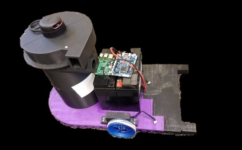
Maker: Team Cleaning Robots

                                      Daniel Khodos
                   Mechatronics Engineering, Vaughn College, Flushing, NY
                             Email: daniel.khodos@vaughn.edu

                                     David Adegbesan
                   Mechatronics Engineering, Vaughn College, Flushing, NY
                            Email: david.adegbesan@vaughn.edu

                                     Oliver Khairallah
                   Mechatronics Engineering, Vaughn College, Flushing, NY
                            Email: oliver.khairallah@vaughn.edu

                                        Faculty Advisor
                                      Dr. Shouling He
             Mechatronics Engineering Department, Vaughn College, Flushing, NY
                              Email: shouling.he@vaughn.edu

ABSTRACT
In this project, the Mechatronics Engineering students from the Department of Engineering and
Technology at a college in the northeastern region of the United States have developed an
innovative robotic vacuuming system. The system consists of two Omni-drive robots: a Slave
Robot (SR) and a Master Robot (MR). The SR works independently. It sweeps dust and dirt from
floor surfaces, including the corners of a room, beneath cabinets, or behind tables and other
furniture. Additionally, it sends information/data to the MR. The MR computes an efficient path
to vacuum dust and dirt in the sections of the room based on the information/mapping transmitted
by the SR. Furthermore, the MR identifies garbage bin locations in an office by using Robot
Operating System (ROS) and a Movidius Image Processing unit and empties them. Two
autonomous robots in the vacuum system are programmed using ROS under Linux Ubuntu. A
LIDAR is installed on each of the robots and path-planning algorithms allow them to navigate
around obstacles. The autonomous teaming robots are mainly designed to clean commercial office
areas. However, they may also be used for residential spaces.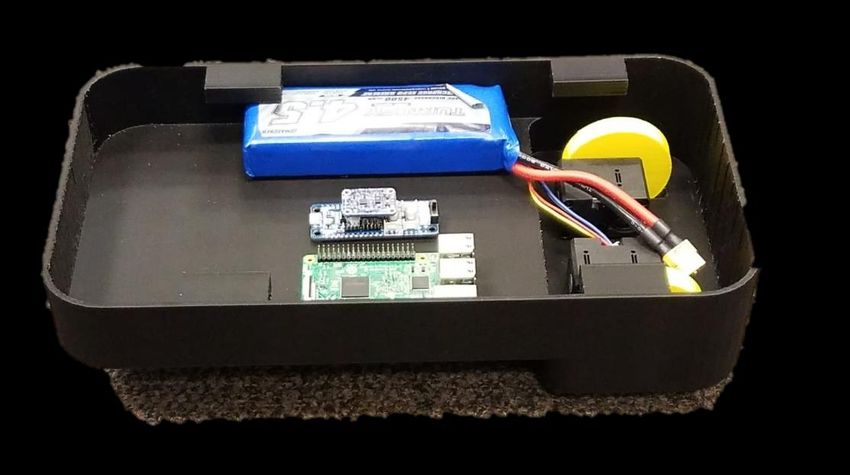
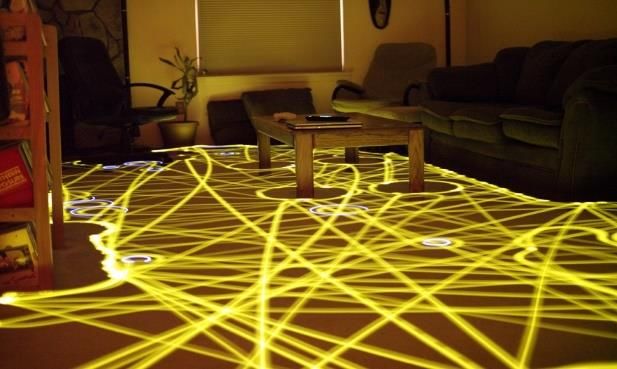
INTRODUCTION
One of the most thankless jobs in office or home areas is vacuuming. It is a duty that sometimes
involves dragging around an unwieldy plastic hose connected to a clumsy wheeled canister for
extended periods depending on the room size. Robot vacuums are a new solution to this mundane
task. These robot vacuums are equipped with lasers, sensors, and even Wi-Fi to navigate around
the home autonomously. Unfortunately, due to their size, form factor, and their lack of intelligence,
these home cleaning robots cannot be utilized on an industrial level. With an increase in the cost
of clean up by cleaning companies, offices and industrial areas with larger spaces will benefit from
an automatic cleaning system. Current automatic cleaning robots are still too clumsy and
inefficient to be used in such a setting.

The objective of this project was to develop a multi-robot system using the ROS framework to
design and implement a completely autonomous and efficient cleaning system. The robots use the
various tools provided by the ROS framework together with sensors to collect and analyze data.
The communication among the robots is used to map and clean an industrial or office environment
more efficiently.

BACKGROUND RESEARCH
A robot vacuum cleaner is an autonomous vacuum system that can make intelligent decisions
based on sensor inputs. The first robot cleaner that appeared on the market was Electrolux Trilobite
[1], a vacuum system developed by James Dizon and purchased by the appliance manufacturer
Electrolux. In 2001, the British technology company Dyson built a vacuuming robot known as
DC06 [2]. However, due to the high cost, it was never released on the market. In 2002, the
American advanced technology company iRobot launched the Roomba floor-vacuuming robot [3].
Due to its small and compact design, and the novelty of owning an automated vacuum, the Roomba
was a large consumer success. Ever since, there have been several variations of robotic vacuum
cleaners on the market. As of 2017, 23% of vacuum cleaners sold are robots [4]. Nevertheless, all
of these robots have a similar weakness, which is the lack of an efficient path planning program,
as shown in Figure 1. They use various sensors, such as sonars and ultrasounds, to detect and avoid
obstacles. But these types of sensors are unable to map the area to be cleaned. As a result, over
the course of operations, a robot can repeatedly vacuum the same 25% of an area while leaving
20% of it uncleaned [5]. To enhance automated vacuum efficiency and to save time and energy,
a modern robot vacuum system with mapping and path-planning algorithms was developed. On
the other hand, a massive robot cleaner would be unable to vacuum the dirt and dust in small or
tight corners due to its large size. However, if the robot is small in size, it may not be powerful
enough to clean a large office area or workshop. Team robots developed in this project will solve
these problems. Further, the MR designed here is also able to empty bin disposal units in an office
area, which makes the current robot vacuum system more appropriate to be applied for office
workspaces.

       Figure 1: Long-exposure photo showing the paths taken by a Roomba over 45 minutes

ENGINEERING REQUIREMENTS AND DESIGN CONSTRAINTS

➢ Specifications for the working environment of the team robot system
   Cleaning area:                      20m×10m

   Time for cleaning:                 120 minutes

➢ Specifications for Master Robot
   •     Size                          620×360×295 mm3
   •     Maximum payload:             2 kg
   •     Body weight:                 28 kg
   •     Maximum speed:                0.22 m/s
   •     Ground clearance:             1 cm
   •     Continuous operation:        120 minutes
   •     Drive hardware configuration: Differential wheeled with 2 drive wheels and 4 casters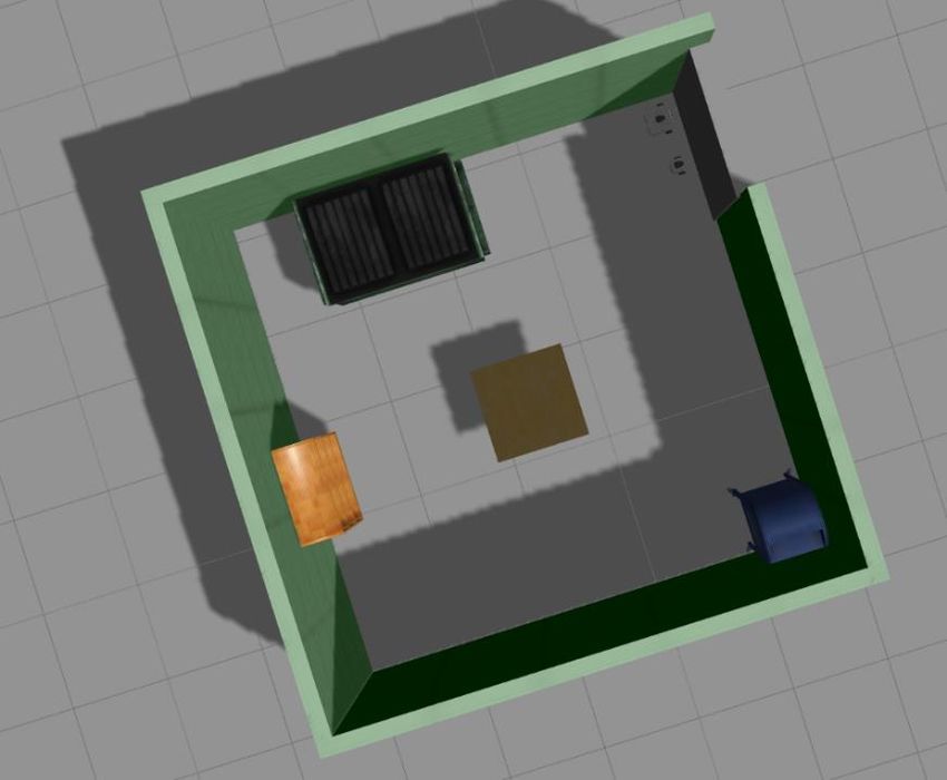
•   Drive software requirement:     Autonomous navigation and obstacle avoidance
   •   Battery requirement:            (x2), 22Ah sealed lead-acid batteries
➢ Specifications for Slave Robot
   •   Size                           250×150×50 mm3
   •   Body weight:                    1.8 kg
   •   Maximum speed:                  0.35 m/s
   •   Ground clearance:                1.5 cm
   •   Continuous operation:          120 minutes
   •   Drive hardware configuration: One motor drives two back wheels and one turning wheel
   •   Drive software requirement:     Autonomous navigation and obstacle avoidance
   •   Battery requirement:             (x1), Zippy 6000 mAh 50C Li-PO Battery
➢ Specifications for motors
       •   Master Robot
           Maixmum torque:             ≥65 kg-cm
       •   Slave Robot
           Maixmum torque:             ≥1.65 kg-cm
➢ Specifications for sensors
       •   Angular range:              360 degree
       •   Detection distance:        0.12m ~ 3.5m
       •   Accuracy:                  1.5cm ~ 17.5cm
➢ Safety requirements
   An emergency stop is incorporated in each robot. In the event of an emergency, when either
   emergency stop button is pressed, both robots will automatically stop. The exhaust port is
   well covered with mesh in order to protect any accidental contact with the vacuum blades.
➢ Health requirements
   A filter installed on top of the exhaust port keeps particles, cleaned from the floor, inside the
   vacuum receptacle.
➢ Summary of Requirements
   This project included the development of two autonomous commercial office-cleaning robots.
   The SR sweeps dust and dirt. It creates a two-dimensional map of its environment using its
   light and range detection (LIDAR) sensor. The MR uses the map transmitted by the SR for its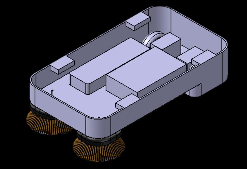
path-planning algorithm and determines the best path for the slave robot and itself to efficiently
   clean the room. Additionally, the MR vacuums dust and dirt swept by the SR.

                           Table 1: Engineering Parts and Specifications

             Items                            Master Robot                       Slave Robot
 Maximum Translational
                                                 0.22m/s                           0.35m/s
 Velocity
 Maximum Rotational Velocity                    1.82rad/s                         2.84rad/s

 Maximum Payload                                  2kgs                               N/A

 Size (L x B x H)                      281mm x 306mm x 141mm               42mm x 29mm x 18mm
 Weight (+ SBC + Battery +
                                                  28kg                              1.8kg
 Sensors)
 Operating Time                                 About 2hr                         About 2hr

 Motor                                     Robotis dynamixel                  Robotis dynamixel
 Single Board Computer (SBC)                 Raspberry Pi 3                     Raspberry Pi 3
 Embedded Controller              OpenCR (32bit ARM® Cortex®-M7)                  OpenCM

 Sensors                                   HLS-LFCD2 Lidar                   HLS-LFCD2 Lidar

                                           3-axis accelerometer              3-axis accelerometer
                                            3-axis gyroscope                   3-axis gyroscope

                                          3-axis magnetometer                3-axis magnetometer

ROBOT CLEANING SYSTEM DESIGN

As it is necessary to develop the behavior of the robots, it is also necessary to optimize their shape,
sensor and actuator system. All of these criteria (shape, sensors, motors, software) must not only
be designed individually, but also as a whole. Only with a total integration of hardware and
software can such an application be feasible.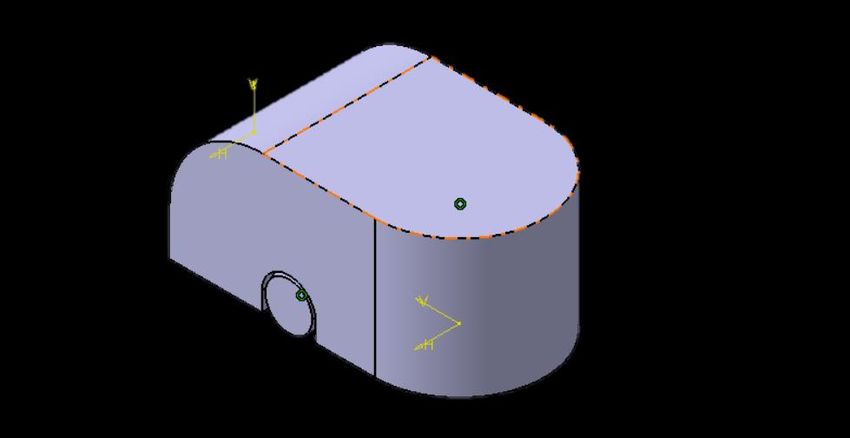
A. ROBOT BODY DESIGN
a) MOTOR SELECTIONS

The MR has a differential drive configuration. Based on the preceding specification, the motor
torque values can be determined first. From the payload value and robot body weight, the motor
torque can be computed. The number of wheels is six, including four caster wheels and two wheels
undergoing actuation. Assuming that the coefficient of friction is 0.6, wheel radius is 5 cm. The
following formulas can be used to calculate the maximum torque applied to the MR for movement:

•   Total Weight of the Robot
                                      WT = WR + P,                                            (1)
where,
     WT = the total weight of the robot
     WR = mass of robot × gravity (mg = 28 [kg] x 9.8 [m/s2] ≈ 275 N)
     P = payload (2 [kg] x 9.8[m/s2] ≈ 20N)
From Eqn. (1), WT can be solved as follows:

                     WT = WR + P = 275 [N] + 20[N] = 295 [N]                                  (2)

•   Maximum Torque Equation ‘T’
If the robot is stationary, the motors attached to the wheels must exert a maximum torque in order
to move. The maximum torque equation can be written as follows:

                       µ×N×r–T=0                                                              (3)
where,
    µ = Coefficient of friction with value of 0.6
    N = Average weight acting on each wheel (Total weight of robot / 2 [N])
    r = Radius of the wheels (5 cm = 0.05 [m])
    T = Maximum torque to get moving [N.m]
Since the weight of the robot is equally distributed among all six wheels, but two are only
actuated, the average weight of the MR can be considered as the total weight of the robot divided
by two. Then, the average weight acting on each wheel can be calculated as follows: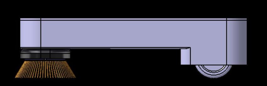
N = WT / 2
                         = 295 [N] / 2 = 147.5 [N]                                              (4)
From Eqn. (3), the maximum torque can be solved by
                 T= µ × N × r = 0.6 x (295/2) x 0.05
                               = 4.425 N-m
                              = 45.15 kg-cm                                                     (5)
To ensure the motors are able to provide enough torque, a motor with the torque larger than 65 kg-
cm for the wheels was chosen. Similarly, for the SR, a wheel radius of 3cm is used. Thus, the
required maximum torque for the smaller robot was calculated and found to be 0.162N-m or 1.65
kg-cm.

b) SENSOR SELECTION

According to the requirements, the power available for team cleaning robots should last for 120
minutes with a cleaning area of 10×20 m2. The accuracy of the sensor measurement must be less
than 17.5cm to guarantee an acceptable navigation. Based on these requirements, the LIDAR
sensor was selected to detect obstacles and provide mapping information of the cleaning area for
the path planning algorithms. Lidar sensors, in particular, provide advantages for obstacle
boundary detection, including a higher resolution over a wider field than other more commonly
used sensors.

c) MASTER ROBOT FRAME DESIGN

First, in selecting the best frame for the application, existing robots on the market were reviewed.
The existing robots were generally round,which is a disadvantage as this does not enable the robot
to clean in corners. Furthermore, a complex trajectory is required to clean around small obstacles,
such as furniture legs, which causes the existing robots to freeze at the obstacle point. Creating a
D-shape robot will be a convenient option for this study.
Figure 2: Isometric View of Master Robot
Figure 2 is the view of the MR as seen from the back left side. The curved surface serves
a dual purpose. It is safer for the user and creates a large access point to the robots internal
collection bin compared to a single flat door. This access allows for easier vacuum
container dumping and facilitates any maintenance that may be necessary. There is one
wheel on either side of the robot, which propel it. The centered location of the wheel allows
for easy control and navigation so that turns can be made on a central axis. The single
wheel is also the support point for the highest concentration of mass of the robot.
Figure 3: Side View Casing Removed of Master RobotFigure 3 shows the side view of the MR with the outer casing lifted allowing the internal
components to be seen. The object labeled (a) is the vacuum head. The two center columns
labeled (b) are the batteries. The batteries are the heaviest components, and as such, require
the most structural support. The object labeled (c) is the wheel, which provides the support
for the batteries and drives the robot. The object labeled (d) is the vacuum container, which
houses the fan and dirt receptacle.
Figure 4: Isometric Casing Removed View of Master Robot
Figure 4 shows the side and top views of the MR with major axis dimensioning. The MR
is 295mm tall, which is large enough to hold a large amount of debris, but still small
enough to fit under most office chairs and desks. The width of the MR is 360mm, which
allows for a wide coverage area of the vacuum head and brush.
Figure 5: Master Robot Assembled Without CasingFigure 5 shows the MS assembled with the casing removed. The motor can be seen
mounted to the base with a wheel attached. The two batteries, Raspberry Pi board and
the motor controller stand at the center of the base. The LIDAR is on top of the vacuum
section to avoid obstruction.
d) SLAVE ROBOT FRAME DESIGN
Figure 6: Isometric View of Slave Robot Design
Figure 6 is the view of the SR from the back left side. Just as the MR, 2 wheels, each
with an individual motor, drive the SR. Two circular brushes protrude from the bottom of
the base and make contact with the floor. These brushes rotate and sweep dust and dirt
from hard to reach places, such as baseboards and corners. The shell protects the internal
components and leaves space for easy access to the battery container.Figure 7: Side View of Slave Robot
Figure 7 is the side view of the SR. Both the wheel and brush can clearly be seen. The tip
of the brush is slightly lower than the bottom of the wheel. This applies pressure on the
brush making a better sweep and more brush to floor surface contact.
Figure 8: Slave Robot Assembled
Figure 8 shows the SR assembled with the two motors mounted at the rear of the robot
and the battery, Raspberry Pi board, and motor controller at the center. The front
compartment is open to allow the brushes to be recessed with their motors in order to
keep dust particles away from any electronic components.
e) ROBOT EQUIPMENT6
4
1
3
5
2
7
8
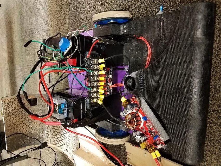
Figure 9: Equipment for Master Robot
Figure 9 shows the various hardware and electronic components of the MR. Each
component is labeled and can be seen in Table 2. The components of the small robot are
similar using much of the same electronic components, specifically the Raspberry Pi 3
(2), Embedded controller (3), 12V 5A Voltage Controller (6), and Dynamixel Motors (5),
along with a continuous 12V motors.
Table 2: Master Robot Equipment Identification
1 Lead Acid Battery
2 Raspberry Pi
3 Embedded Controller
4 12V 22A Voltage Controller
5 Dynamixel Motors
6 12V 5A Voltage Controller
7 Power Distribution
8 5V 10A RelayB. ROS SYSTEM, SIMULATION AND SOFTWARE FLOWCHART
The cleaning robots are programmed using ROS, an open source framework that allows the
development of multiple components of a robotics system with the goal of sharing and porting
them to other robots with minimal changes. It is an operating system that provides regular
service a user would expect, including hardware abstraction, low-level device control,
implementation of commonly-used functionality, message-passing between processes, and
package management. The ROS environment also provides tools and libraries for obtaining,
building, writing, and running code across multiple computers [6]. Programs in ROS utilize
processes called Nodes to perform computation. These processes communicate with one
another by publishing and subscribing to messages via named buses known as Topics. These
nodes are developed to operate on a minuscule scale; a robot control system will usually
comprise many nodes. For example, one node controls the on/off switch of a laser range finder,
another controls the robot's wheel motors, the third one performs localization, the fourth node
performs path planning, and so on [7]. One major benefit of multiple nodes is an increase in
fault tolerance as crashes in a system are isolated to individual nodes in the program.
Figure 10: Node Communication
As a part of the robot design, the programs and algorithms are simulated using a tool in ROS
called Gazebo. Gazebo is a multi-robot simulator for complex indoor and outdoor
environments. It is capable of simulating a population of robots, sensors, and objects in a three-
dimensional world. It generates both realistic sensor feedback and physically plausible
interactions between objects [8]. In the Gazebo simulator, the user will design an environment
and spawn robot models into it. The developed algorithms can be tested and improved basedon the results obtained from the simulation. To speed up the experimental process, two
TurtleBot3 robot models, burger and waffle, were used for performance verification and
validation. The TurtleBot3 models have open-sourced robot description files that can be
modified for specific needs [9].
Figure 11: Gazebo Simulated World with Master and Slave RobotsFigure 12: Gazebo Class Program Figure 13: Control Loop for Robots in Gazebo
Figure 14: Simulation Algorithm Flowchart

Figure 14 shows the program flowchart for simulation. At the start of the program, a memory
check determines whether there is any existing map of the location. If a map already exists, the
MR proceeds to path plan its navigation around the room to clean it efficiently. If there is none,
the SR starts mapping the area and upon completion, shares the map with the MR. If the map is
shared successfully, the MR starts the path planning and the SR enters standby mode. On the other
hand, if the MR does not receive the map, the SR repeats the process of mapping the area. Once
the path planning is complete, the MR proceeds to navigate and vacuum the mapped area. If an
obstacle is met on the way and it is deemed cleanable by the SR, the MR directs the SR to clean
the area. The SR exits standby mode to perform its designated function of cleaning a specified
area. Once done, the SR resumes its standby mode and awaits further instruction from the MR.
The MR repeats this process until it is finished navigating the mapped area. This ends the
vacuuming process, which in turn ends the whole program.

C. ROBOT CONTROL AND NAVIGATION

The two robotic vacuum cleaners are controlled using two embedded microcontrollers, OpenCR
and OpenCM. The OpenCR is an open-source control module for ROS, with a STM32F7 chip
based on the ARM Cortex-M7 while the OpenCM is based on the ARM Cortex-M3. Both
controllers are used to control the sensors and actuators on the robots. To communicate between
the embedded controllers and the Single Board Controllers(SBCs), we utilized the rosserial
package. This is a package that converts ROS messages, topics and services from the SBC to a
serial communication to the embedded controllers. To navigate, data from the LIDARs and
Inertial Measurement Units (IMU) are sent to the SBC to determine the robot’s pose on the map.
The robot’s location is then compared to the target location and the SBC performs the SLAM
operations to determine the motion required to get the robot to the target. These motion
parameters are sent to the dynamixel motors with built in encoders to precisely rotate the wheels.
Feedbacks from the wheels encoders are used by the SBC to ensure the robot has reached its
target.

CONCLUSION

Robotic vacuum cleaners are gaining popularity among consumers with the desire to save time
during weekly vacuuming. Many existing robots have designs that implement spinning brushes to
reach tight corners, while others incorporate cleaning features such as mopping, waxing, UV (Ultra
Violet) sterilization, etc. However, they do not effectively map and plan their vacuum operation
paths. Using tools and frameworks in ROS, the objective of this project was to design a cost-
effective and user-friendly robot vacuuming system to increase the efficiency and capabilities of
the current systems. The development of this system will encourage the creation of similar systems
that may be integrated into many home Internet of Things (IoT).

REFERENCES

[1]   1997/2002 - Electrolux Trilobite Robotic Vacuum Cleaner - Anders Haegermarck, Lars
      Kilstrom, Bjorn Riise (Swedish). (2013, October 09). Retrieved December 28, 2017, from
http://cyberneticzoo.com/early-service-robots/19972002-electrolux-trilobite-robotic-
vacuum-cleaner-anders-haegermarck-lars-kilstrom-bjorn-riiseswedish/
[2] Dyson's big, heavy, complicated robot vacuum that never was. Retrieved January 08, 2018,
from https://www.engadget.com/2015/10/23/dysons-big-heavy-complicated-robot-vacuum-
that-never-was/
[3] About iRobot. (n.d.). Retrieved January 07, 2018, from http://www.irobot.com/About-
iRobot/Company-Information.aspx
[4] You rest, they work. Best robot vacuums of 2017. (n.d.). Retrieved December 18, 2017,
from http://tenrows.com/robot-vacuum/
[5] Layton, J. (2005, November 03). How Robotic Vacuums Work. Retrieved December 17,
2017, from https://electronics.howstuffworks.com/gadgets/home/robotic-vacuum2.htm
[6] ROS, Introduction. Retrieved January 26, 2018, from http://wiki.ros.org/ROS/Introduction
[7] ROS, Concepts. Retrieved January 26, 2018, from http://wiki.ros.org/ROS/Concepts
[8] Gazebo, Get Started. Retrieved January 25, 2018, from http://gazebosim.org/#getstarted
[9] Robotis, TurtleBot3. Retrieved January 12, 2018, from
http://emanual.robotis.com/docs/en/platform/turtlebot3/overview/You can also read