Technical Report - Quality Software ...
←
→
Page content transcription
If your browser does not render page correctly, please read the page content below
Technical Report

                              Parallel Production System Engineering -
                                       Industry 4.0 Testbed Case Study

                                                                          Petr Novak1
                                                                         Jiri Vyskocil1
                                                                         Petr Kadera1
                                                                    Lukas Kathrein2,3
                                                                    Kristof Meixner2.3
                                                                   Dietmar Winkler2,3
                                                                          Stefan Biffl3

        1 Czech   Institute of Informatics, Robotics, and Cybernetics, Czech Technical
                                          University in Prague, Prague, Czech Republic
                                                       .@cvut.cz
          2 Christian
                    Doppler Laboratory for Security and Quality Improvement in the
    Production System Life Cycle, Institute for Information and Systems Engineering,
                                                             TU Wien, Vienna, Austria
                                               .@tuwien.ac.at
                                         3TU   Wien, Information Systems Engineering,
                   Institute for Information and Software Engineering, Vienna, Austria
                                                .@tuwien.ac.at

Technical Report No. CDL-SQI 2019-14
Issued: June 2019
Citation: P. Novak, J. Vyskocil, P. Petr Kadera, L. Kathrein, K. Meixner, D. Winkler, and S. Biffl „Parallel Production System Engineering – Industry 4.0 Testbed Case Study“, Technical Report CDL- SQI 2019-14, TU Wien, Vienna, Austria, June 2019.
Parallel Production System Engineering –
                   Industry 4.0 Testbed Case Study
         Petr Novák∗ , Jiřı́ Vyskočil∗ , Petr Kadera∗               Lukas Kathrein† , K. Meixner† , D. Winkler† , Stefan Biffl‡
 ∗   Czech Institute of Informatics, Robotics, and Cybernetics                     †  Christian Doppler Laboratory CDL-SQI
            Czech Technical University in Prague                              ‡   Institute for Information Systems Engineering
                     Prague, Czech Republic                                           Technische Universität Wien, Austria
                 {firstname.lastname}@cvut.cz                                          {firstname.lastname}@tuwien.ac.at

   Abstract—Production systems are complex automated systems.            waterfall model for production system engineering is used.
Their design phase relies on cooperative work of engineers of            The cascading waterfall model includes the following basic
different disciplines. This technical report is focused on system        process steps:
engineering on the technical system level design as well as on the
automation and control engineering for production systems. The              1) Requirements
system integration is demonstrated on the case study dealing with           2) Design
Industry 4.0 Testbed. This educative and testing facility includes a        3) Implementation
monorail transportation system and four robotic work cells. The
                                                                            4) Verification
main contribution of this technical report is the specification of
engineering roles and interactions among these engineers, which             5) Maintenance
compose the engineering process for production systems. The key          The problem of the cascading waterfall model is that if some
contributions from the presented case study from Industry 4.0            changes or flaws emerge or are found out in later process steps,
environment are the lessons learned from Industry 4.0 Testbed
and the specification of cooperation of engineers in production
                                                                         their incorporation means extreme time and costs. “When all
system design.                                                           these factors are considered, changes typically cost anywhere
   Index Terms—Industry 4.0, production system engineering,              from 50 to 200 times less if you make them at requirements
flexible manufacturing, artificial intelligence, machine learning        time than if you wait until construction or maintenance” [1].
                                                                            Current production system engineering therefore has to shift
                                                                         towards agile engineering in a similar how, how it is in
                       I. I NTRODUCTION                                  software engineering. The main artifacts that is updated during
   Engineering phase of emerging cyber-physical production               design-phase of production systems are types of devices and
systems (CPPS) and Industry 4.0 systems relies on parallel               signals. The signal interfaces change during design frequently
work of various domain experts and teams. Such a parallel                and in the iterative manner.
engineering includes backflows of knowledge and data.                       During evolution of the system, state of artifacts has to be
   To align the discussed approach within production system              considered and changes should be traced, such as in a ticketing
engineering concept in general, the three fundamental scenar-            system. For doing this, we need to address:
ios for system engineering can be distinguished:                            1) Formal model of the process
   1) From scratch according to specified target products                   2) Analysis of limitations of the process
   2) Universal/flexible manufacturing line                                 3) Process improvement options
   3) Hybrid approach of both aforementioned                                Production systems are systems-of-systems – from the re-
   We focus on the second scenario for the following rea-                sulting point of view they are components. Lead to a high
sons. The first scenario is too product-specific and does not            structural complexity The formalization targets elimination of
fulfill requirements of the current market. The third one is             design-time errors that should result into faster, less expensive
very complex with numerous pieces of legacy hardware and                 and more safe ramp-up phase including making system up and
software with relics from history that does not meet state of            running as well as its testing, debugging, and fine-tuning.
the art principles. The selected scope on the engineering of                This technical report describes lessons learned in the design-
universal/flexible manufacturing line fulfills requirements on           phase of Industry 4.0 Testbed. We investigate to what extent
flexible manufacturing lines that are in compliance with the             the design process can be supported with existing industrial
current Industrie 4.0 movements. Last but not least, such a              standards with the main focus on AutomationML.
kind of universal manufacturing line is being developed and                 The remainder of this technical report is structured as
maintained by the authors of this paper and thus it can be               follows. Section II formulates the research issues that are
utilized as a case study for the evaluation reasons.                     addressed and answered in this technical report. Section III
   In the classical production system engineering (PSE) sce-             summarizes the state of the art on PSE, engineering process
narios that are still used nowadays in industrial practice, a            analysis, and approaches for knowledge sharing in PSE. Sec-
tion V specifies relevant engineering roles in the production to consider dependencies between the engineering disciplines
system engineering as well as data exchanges among them. in order to build a common system. To shorten the duration
These interactions are depicted in an interaction diagram, of PSE projects, parallel engineering, takes place, so-called
which is a proposed interaction model suitable for further Round-Trip Engineering (RTE) process to iteratively enrich
usages. Sec. VI proposes an information model on common and refine engineering artifacts [6]. Similar to RTE in software
concepts for knowledge exchange, integration, and sharing engineering [7], its main goal is the synchronization of two or
between the PSE domain experts identified in Section V. more engineering artifacts to ensure consistency.
Section IV demonstrates the proposed methodology on the In this paper, we look at the activity sequence of engineering
Industry 4.0 Testbed. Section VII concludes and proposes actions and the engineering tools supporting PSE actions.
future work. Recent research has indicated that the waterfall model of
the PSE process described in standard literature, such as
II. R ESEARCH Q UESTIONS
the VDI guidelines 2221 [8] and VDI 2206 [9], is used in
The engineering of Industry 4.0 production systems requires practice for planning, whereas the applied process often differs
high flexibility and short update cycles to synchronize the considerably from the waterfall paradigm, routinely leading to
results of collaborating workgroups that work in parallel. The a conceptual mismatch between plan and action. In current
traditional point-to-point data exchange between workgroups practice, PSE processes often follow a round-trip-engineering
makes it hard to keep an overview on the engineering artifact (RTE) pattern, characterized by an increasing (i) parallelization
versions. To address these challenges, we derive the following of engineering activities [10] and (ii) number of engineering
research questions. cycles to improve the set of engineering artifacts towards
• RQ1: What information do domain experts exchange in a production system model applicable to production system
a typical Industry 4.0 engineering project? installation [11]. Hence, the software tool support for the PSE
In this paper, we analyze the information exchanged in process could benefit from a comparison to software tools that
a case study of the Industry 4.0 testbed at TU Prague. support processes for agile programming in business software
We follow the design science approach [2] and apply the engineering [12] that have extensive experience with iterative
engineering process analysis method [3] to (a) derive a approaches.
process model of the major tasks and roles in PSE and In the context of production systems, the control logic is
the most relevant data they exchange and (b) model the typically implemented by PLCs. A family of PLC program-
common concepts that two or more roles share in the ming languages is standardized as IEC 61131. Based on this
PSE process as foundation for designing a repository of standard, PLC are normally programmed with Structured Text,
engineering artifacts that the domain experts can enrich ladder diagrams, or function block diagrams [13]. However,
along the PSE process. there are numerous extensions and variations that are vendor-
• RQ2: To what extent can the process be supported dependent. Another standardization effort in the frame of a
with a standard from the automation domain, such as standard PLCopen is trying to bridge the gap between various
AutomationML? PLC programming implementations1 . Higher levels than PLCs
Standardization plays a key role in project consortia when are frequently implemented with Python, C#, or Java, data
data has to be exchanged among industrial partners. This acquisition can be implemented in the C language.
research question is focused on identification whether Expressivity of languages such as Python is Turing com-
there are important limitations. If yes, we try to pinpoint plete. Therefore, there is a halting problem which is unde-
the blindspots that should be standardized in future. In cidable and thus it is hard to verify that the program fulfills
other words, this research question considers the result requirements. On the contrary, PLCs originate from finite
of RQ1 as an interaction model and based on this model automata, which means that engineers can formally verify
it targets on recommending what should be standardized the PLC code. There are tools available for the PLC code
further. verification [14]. This is an important strength of PLCs and
III. S TATE - OF - THE -A RT their languages.
Industrial robotics typically utilizes proprietary languages.
A. Production System Engineering (PSE)
For example, the robot vendor KUKA2 uses the language KRL
Engineering industrial production systems, so-called cyber- for the traditional industrial robots, which represents the most
physical production systems, e.g., long-running and safety- significant part of KUKA portfolio, whereas the new advanced
critical systems for assembling automotive parts or for pro- type of cooperative robots uses the Java language. Due to the
ducing metal, is the business of multi-disciplinary production use of a large set of different programming languages in PSE,
system engineering (PSE) companies [4], [5]. Planning such the verification and validation of correct operations and correct
systems involves parallel engineering: Due to increased pro- systems behavior are challenging. This is also an issue during
duction cycles multiple disciplines, such as mechanical, elec- maintenance and evolution, and even minor updates or changes
trical, and simulation engineering, develop their engineering
and artifacts, such as plans, models, software code, or ma- 1 PLCopen: www.plcopen.org/
chine configurations, independently. Nevertheless, they have 2 www.kuka.comof the system during production system lifecycle may imply The process of data integration in industrial automation
high testing effort and costs. is standardized in ISA-95 [21]. ISA-95 (resp. IEC 62264)
and focuses on vertical integration of automation tools and
B. Process modeling and formalization data models within the automation pyramid. However, ISA-
Business Process Model and Notation 2.0 (BPMN 2.0). 95 does not provide a communication language but rather a
The BPMN standard from the OMG (2011) in its second methodology to define data models for the integration of MES
version tries to provide an easy to understand modeling and ERP systems.
approach with rich semantics, to be understandable by experts Semantic models for industrial systems can be represented
and non-experts alike [15]. For achieving this goal, BPMN in an OWL5 ontology according to the standard ISO 15926
provides several clearly defined concepts like tasks, events, [22]. Although the standard originally addressed issues in
gateways, and comments. Swim lanes can be used to model the the oil and gas industry, the concepts are applicable also in
responsibilities of different actors or workgroups, highlighting other types of production systems. The original version of the
potential interfaces between domain experts that can be used standard utilized EXPRESS language, but due to its limited tool
for improving an engineering process. While swim lanes make support, the OWL system description was added, see online at
it easy to analyze the interfaces between neighboring swim the POSC Caesar Association6 for details.
lanes, it may be difficult to analyze the interfaces between
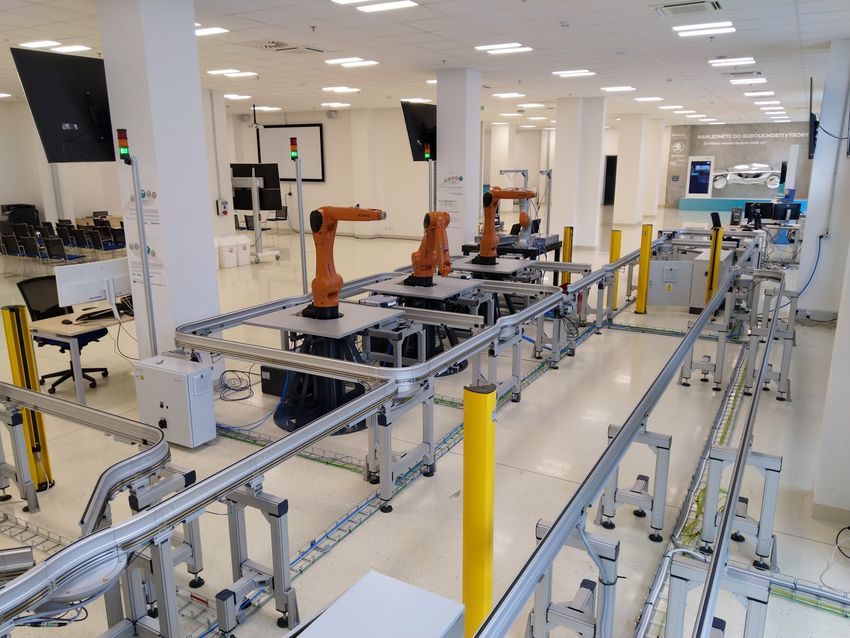
IV. I NDUSTRY 4.0 T ESTBED U SE -C ASE
swim lanes that are not direct neighbors, in particular, if there
are many swim lanes or actors as in the case discussed in this The paper targets on designers of an assembly production
paper. system. Industry 4.0 Testbed at CTU in Prague is utilized as
UML-Activity Diagram (AD). UML activity diagrams also an example. It is equipped with I4.0 infrastructure that can be
provide the means to process flows, as concepts such as tasks, programmed, no legacy systems involved. It is a smaller scale
flows, gateways and a document flow, similar to BPMN 2.0, environment, however, the presented approach is scalable to
are present. UML-ADs are very popular in the computer larger manufacturing lines.
science community [16]. However, UML-ADs are not as The entire cyber-physical system is depicted in Fig. 1. The
widely used by engineering domain experts [3]. most apparent part of this experimental system is a monorail
IDEF0 [17], provides a very easy to understand syntax transportation system Montrac. It consists of rails called tracs,
and semantic, which is due to its limited number of differ- trac curves, trac switches, and positioning units that assure
ent modeling elements. Activities (boxes), Inputs, Outputs, exact position of shuttles in working cells.
Controls and Resources (all depicted as arrows) are the sole Three positioning units of the Montrac systems are accessed
elements of an IDEF0 diagram. Due to its ease of use by four industrial robots. Each positioning unit is shared
and understandability, IDEF0 diagrams are widely used in between two robots. This layout brings opportunity for coop-
engineering projects [18] and facilitate the effective commu- eration between robots, which can be beneficial for example
nication between process analysts and the customer [19]. In for final assembly.
small diagrams, is IDEF0 a very helpful choice, as it allows The Industry 4.0 Testbed is equipped with industrial robots
a quick sketching and modeling. In this paper, we build on of the two types:
the IDEF0 modeling approach as IDEF0 models with many • 3x KUKA KR Agilus: Very fast industrial 6-axis robots
actors are easier to analyze than the interfaces between many programmed in the language KRL
swimlanes in BPMN2.0. • 1x KUKA LBR iiwa: Modern cooperative 7-axis robot
programmed in the language Java
C. Industrial standards as Candidates for Knowledge Sharing
For testing purposes, assembling Lego bricks is used to eval-
for PSE Standardization
uate designed approaches, algorithms, and tools in Industry
Prominent role plays the European effort in the frame of 4.0 Testbed. The final Lego product is drawn in Lego Digital
Asset Administration Shell codification. One of the main corner Designer7 . This drawing is transformed to the problem file in
stones of this standardization effort is a data format called the PDDL notation. The planner and scheduler are utilized
AutomationML. to plan the production recipe in the form of LispPlan. The
AutomationML3 [20] is an XML-based and standardized exemplary final product designed in Lego Digital Designer is
data format (IEC 62714) for representing and exchanging depicted in Fig. 2. This assembly is uploaded via MES GUI
engineering knowledge in the area of process automation and to the Plan Executor, which hands it over to the planner. After
control. AutomationML aims at integrating a set of growing planning the production operations, the plan is captured in the
standardized data representations, such as CAEX for plant lisp plan format. Subsequently, the production is scheduled
topology information (IEC 62424), COLLADA4 for geometry and then executed by the Plan Executor by means of OPC
and kinematic information, and PLCopen XML for logic UA communication to/from the shop floor.
information.
5 OWL: www.w3.org/OWL
3 AutomationML:
www.automationml.org 6 PCA: www.posccaesar.org/wiki/ISO15926inOWL
4 COLLADA: www.khronos.org/collada 7 https://www.lego.com/en-us/ldd/downloadFig. 1. Industry 4.0 Testbed at the Czech Technical University in Prague – CIIRC. Fig. 2. Lego tower as a product to be built by the production system, exported from Lego Digital Designer 4.3.11.
V. E NGINEERING ROLES IN PSE                           C. Production planner and scheduler (PPS)
   We collected and analyzed data on an Industry 4.0 PSE or-            Production planning and scheduling requires a broad range
ganization in a case study [23] by conducting process analysis       of knowledge. PPS has be (i) able to formalize (into the
tasks with stakeholders from workgroups on their exchanged           computer-understandable form) all operations that can be
artifacts in order to identify engineering artifacts and data that   performed on the line. Each operation is characterized by
are candidates for sharing in a common repository.                   resources that are used (incl. expected durations) and by
   From interviews with domain experts and managers we               semantics from the product and manufacturing line point of
derive a Data Processing Map [3] represented as an IDEF0             view. PPS (ii) specifies the status of the line, incl. material
diagram with key PSE tasks, stakeholder roles and the en-            status, warehouse management, allocation of resources, etc. He
gineering information that traditional is exchanged directly         or she has to be able (iii) to formulate the goals of the planning
between a data provider and a data consumer. We describe the         problem. Last but not least, (iv) PPS initializes computer-based
roles, their goals and tasks as well as the inputs and outputs       planning, addresses occurring problems, optimizes the formal
of their tasks as foundation for deriving a data model of the        specification and performance of the solver by improving its
shared common concept data that is embedded in the engi-             parameter settings.
neering artifacts and data. We identified relevant engineering          PPS has the following inputs: outputs of PD and PST.
roles in production systems engineering, which are depicted             PPS has the following outputs:
in Fig. 3. These roles are discussed in details in the following        • Problem and domain specifications in PDDL
text, including required knowledge/skills for each engineering          • Production schedule (i.e., graph of production operations
role, as well as inputs and outputs.                                      mapped to time, resources, dependencies)
A. Product designer (PD)
                                                                     D. Transportation system designer (TSD)
   Product designer designs a target product and implements
its physical prototype. The required knowledge for this role            TSD designs the HW part of the transportation system.
is a basic overview about main components of the production          This engineer has to have knowledge about what can be
line (maximal weights, precision, dimensions, etc.).                 transported and under what conditions (incl. speeds, accelera-
   Inputs for the PD engineering role are:                           tions/decelerations, weights, temperature, relative humidity).
                                                                        Input is specification of the topology of the system and types
   • CAD drawing of a product negotiated with a customer
                                                                     of equipment to be used. This is specified in cooperation with
     accompanied with natural language description. This is
                                                                     PST and this specification can be round-trip engineering.
     the entry point to the presented approach and this cannot
     be fully automated most likely.                                    The output of TSD is a technical specification and descrip-
   • Production facility constraints as a feedback from PST
                                                                     tion of the transportation system.
     and PPS.
                                                                     E. Transportation system integrator (TSI)
   The PD role has the following outputs:
                                                                       TSI develops a control code that performs the operations
   • After decomposition of the production problem, he or
                                                                     that are specified by PPS Tests and verifies/validates the
     she should specify a product as a goal for PST in natural
                                                                     control code
     language
B. Production specialist / Technologist (PST)                        F. Robot work cell designer (RWCD)
  PST identifies and specifies changes related to target product        RWCD basically designs specific types of robots and their
and to improve the value-chain process. He or she has to be          mounting. The fundamental knowledge background is (i) an
skilled in analyzing processes, their improving and extending,       overview about robots incl. maximum loads, absolute and
and decomposition.                                                   relative precisions, environmental parameters, size and reach-
  The inputs of PST are:                                             ability space, positions of robot singularities and knowledge
  • Decomposed product from PD
                                                                     how to avoid them. In addition, RWCD has to have (ii)
  • Detailed insight into components and their related oper-
                                                                     a mechanical background related to mounting of the robot,
      ations on the current production line                          design of pedestals, robot tables, vibrations, etc. Last but not
                                                                     least, (iii) mathematical background about coordinate systems
  Outputs of PST:
                                                                     and their translations is required.
  • Identifies standard operations being common among
                                                                        Input:
      products and resources. Standard operations can be spec-
                                                                        • Specify in cooperation with PST topology of the system
      ified in AutomationML/ISA-95.
                                                                           and types of equipment
  • Identifies operations that are not yet supported and ini-
      tiates updates by requiring to program something or               Output:
      purchase something. For some of the missing artifacts,            • Realized robot cells from the HW perspective
      they can be specified in AutomationML/ISA-95 or all               • Methodology of robot calibration (when and how to cali-
      can be specified in natural language exactly.                        brate the robot, calibration support for required precision)
Production Specialist / Production Planner
Technologist Operations and Scheduler
PST PPS
Low-level integration feedback
Transportation Connections Transportation
System Designer System Integrator
Systems and topology Interfaces Cloud / Edge Engineer
TSD TSI CEE
Topology feedback
Low-level integration feedback
Decomposition
Production data
Product Designer Operations Robot Cell Designer Robot Programmer
Robots Robot Programmer
PD and equipment specification RCD Interfaces
RobotRP
Programmer
RP
RP
Low-level integration feedback
System Integrator PLC system PLC Prgrammer
architecture PLC Prgrammer
Operations and SI Interfaces PLCp
PLC Prgrammer
high-level overview of interfaces PLCp
Operations
Interfaces
PLCp
and specification Interfaces
Pneumatic System
Pneumatic requirements Engineer
Quality Engineer Pneumatic requirements PSE
QE Interfaces
SCADA HMI Engineer
Simulation models
HMIe
All Detailed description of systems Simulation Engineer Interfaces
engineers from all engineers SE Manufacturing Execution
System Engineer
MESe
All Administrative and logistic support Project Manager Operator
engineers and supervision of all engineers PM Interfaces
Op
Fig. 3. Data Processing Map of PSE Engineering roles in the Industry 4.0 case study context, based on [3].
G. Robot programmer (RP) Second, SI has to be knowledgeable about safety and secu-
RP implements robot operations such as parameterizable rity (incl. various types of authentication). Third, hardware-
pick and place operations. The required knowledge are robot- specific representation of numbers (such as Little-/Big-Endian
specific programming languages (such as KRL, Java for LBR problem, expressing negative numbers, fixed-point arithmetics,
iiwa, ROS, Karel), as well as knowledge about robot-specific floating-point arithmetics floats). Last but not least, SI has to
IDEs (such as KUKA WorkVisual, Sunrise WorkBench, ABB be skilled in representation of characters (such as ASCII, UTF-
Rapid, Microsoft Robotics Developer Studio) including ver- 8, Unicode).
sion constraints. Inputs of SI:
Inputs: • Interfaces of programs created by the roles TSI and RP.
• Implements operations specified by PST, RWCD, PPS Outputs of SI:
Outputs: • product/ion specification by PST and PPS.
• In case of issues, reports back to TSD, PST
I. PLC programmer (PLCp)
H. System integrator (SI) PLC programmer implements PLC programs. He or she
SI sets up communication, safety programs, making com- has to know IEC 61131-3 languages (i.e., ladder diagram,
ponents up and running. structured text, function blocks), in some cases high-level
The required knowledge is related to all devices/machines language like C is needed. Next, knowledge about specific
to be integrated (robots, transportation system, pneumat- extensions of various PLC vendors is needed (such as real-
ics), their communication protocols (Ethernet-based field- izations of OPC UA servers on particular PLCs, EtherCAT,
buses, GPIB, RS-485, RS-422, RS-232C) and communication ProfiNet or ProfiBus integration etc.). PLCp have to be skilled
patterns (master-slave, publish-subscribe, peer-to-peer, multi- in safety functions programming and signal patterns required
master), and communication standards such as (OPC classic, by robots. Finally, methods for formal and experimental veri-
OPC UA, OPC Xi, IPv4, IPv6, TCP/IP, UDP datagrams). fication/validation of implementation are needed.Inputs: M. Project manager (PM)
• Interface specification from RP with cooperation to SI PM coordinates the entire project on the managerial level
Outputs: and synchronizes the work of engineers. He or she pins up the
engineering effort and maintenance process.
• Program for PLC Inputs:
• Work progress of all engineers
J. Pneumatic system engineer (PSE) Outputs:
PSE designs the entire pneumatic system and its control. • Work tasks leading to the finished project
The mechanic-oriented knowledge has to cover a pneumatic
hardware portfolio (including compressors, filters, logic struc- N. Simulation engineer (SE)
tures, valves and valve terminals, plastic pipes, robotic han- SE creates virtual twins of the production system, produc-
dling systems such as grippers, sensors, pneumatic drives, tion resources, and production processes. They model diverse
servo-pneumatic positioning system, vacuum technology, fit- technologies with diverse tools.
ting equipment). Programming-oriented knowledge has to be SE has to have a mathematical-physical background to
related to pneumatic controllers and their programming. model components of the production systems, production
Inputs: operations, and products. Knowledge about general-purpose
simulators (such as MATLAB-Simulink, Modelica-based sim-
• Pneumatic requirements from RWCD
ulators) or industrial-oriented simulator tool suites (such as
• Pneumatic requirements from TSD
Siemens Plant Simulation, Process Simulate) is also needed.
• Safety requirements from SI
The required skill is ability to efficiently create a simulation
Output: model and to encapsulate it to the digital twin. Last but
• Pneumatic system up and running not least, SE has to optimize the model, and usage of data
analytics for fine-tuning of the model with real measured data
is needed, as well as the abstraction of the physical behavior,
K. SCADA HMI engineer (HMIe)
agile adaptations of the simulation model.
HMIe designs a control panel with visualisation of the Inputs:
production system. The required knowledge covers (i) mod- • Complete system description of all engineering disci-
ern Web-based technologies (such as HTML 5.0, JSON, plines
AJAX, WebSocket, https) and various frameworks (such as Outputs:
AngularJS, BabylonJS). As well, the (ii) traditional desktop
• Digital twins
approaches such as Siemens WinCC or National Instruments
LabWindows/CVI are needed. Finally, (iii) ergonomic require- O. Quality engineer (QE)
ments specified by the High Performance HMI [24] have to
QE designs qualitative and quantitative requirements and
be incorporated into the final appliaction.
tolerances in order to produce products in a good quality. QE
Inputs: designs testing procedures and tests samples of the products.
• OPC UA interface specification from SI He or she specifies and checks AQL (i.e., Acceptance Quality
Outputs: Limit according to ISO 2859) related to products. QE has to
be skilled in searching for possible roots of quality defects
• SCADA HMI and issues. He or she has to have material and mounting
knowledge, background, and skills. QE also drives aging tests.
L. Manufacturing execution system engineer (MESe) Inputs:
• Production specification from PST and PPS
MESe designs a MES system, respectively adopts/adapts
• Detailed operation description from TSI and RP
existing MES to a new application. He or she also supervises
• Digital twin from SE
the overall production process and manually intervene if it is
needed when the automated system is not able to recover in- Outputs:
dependently. Moreover, MESe is responsible for an interaction • Specifies qualitative parameters of all operation for PST
of MES with ERP systems, hence this is the further skilled to
be met by this engineer. P. Cloud/edge engineer (CEE)
Inputs: Design data acquisition and big-data analytics system on the
cloud and edge level Cloud-based technologies (such as Mi-
• Information from PST and SI
crosoft Azure, Amazon Web Services, Siemens MindSphere,
• Requirements from IT and ERP
etc.)
Outputs: Inputs:
• MES • MES description from MESeTABLE I real production system components. It can be done in several
I NFORMATION FLOWS AMONG ENGINEERING ROLES . ways with AutomationML, however, the recommendation of
Product Process Resource the best practice is missing in the current version of the stan-
Prod. operation
dard nor in the white papers published by the AutomationML
HW topology
Semi-product
Specification
Component
Simulation
Pneumatic
Prod. data
Prod. plan
Transport
Interface
Office8 .
Robot
Role
PLC
VII. C ONCLUSION AND F UTURE W ORK
PD w
PST r w w w r r
PPS r r
This paper presents a new design methodology for produc-
TSD r/w w w r tion systems. It reflects needs required in a Industry 4.0 con-
TSI r r r text, related to the high flexibility, parallel work of engineers,
RCD r w w r
RP r r r and short update cycles. In this context, getting and keeping an
SI r r/w w r overview about changes and status of the overall engineering
PLCp r r r
PSE r r r project is of a high importance.
HMIe r/w r The proposed approach is based on abstracted and semi-
MESe w r r
CEE r r formalized lessons learned gained in engineering process
Op r r r of Industry 4.0 Testbed at the Czech Technical University
QE r r r
SE r w
in Prague – CIIRC. The distributed nature of the system,
PM r r consisting of mechatronic components, is reflected and the
system is thus considered as a system-of-system. To fulfill
all functional and non-functional requirements, the proposed
• OPC UA interfaces from SI methodology formalizes a new agile-oriented methodology
Outputs: expecting cooperative work of various domain experts.
• Historian The proposed approach moves from a point-to-point data
• Life-cycle of products exchange towards a central repository for common data. This
• Predictive maintenance system paper also answers how to organize the central repository in
• Asset administration shell terms of its data model and interactions with engineering roles.
Addressing the research question RQ1, we formulated what
Q. Operator (Op) are the key engineers/engineering roles in typical Industry 4.0
Op is responsible for running the system and production. production system engineering projects. We also specified
Ops are trained to start up and run the production, observe the information that is exchanged among engineers. These results
operation and stops at emergency. They perform operations are are graphically depicted in Fig. 3 and summarized in
that have no automation yet (such as putting in a raw material Tab. VI.
and handing over final products). They have to be able to In the frame of the research question RQ2, found out
provide feedback from the production to the engineering team, that the AutomationML data format is suitable for storing
mainly to the PST. information for the purpose of the central repository. The
Inputs of Op: resulting recommendation for the standardization effort is
• HMI from HMIe from the user/operator point of view to incorporate support for simulation modeling and virtual
twinning as part of the standardization process.
VI. I NFORMATION M ODEL FOR P RODUCTION S YSTEM Both our experiences form Industry 4.0 Testbed and the
E NGINEERING analysis presented in this paper proves that the critical point
To design an information model for data exchange in PSE, of the engineering team is PST. On the contrary, he or
we had to analyze the aforementioned data flows among she does not need to have any detailed knowledge about
engineers. Such data flows can be summarized as it is done specific programming languages or system platforms. A very
in Tab. VI. When an engineer is nominated to be a member skilled and educated person has to be a robot programmer,
of a PSE team, he or she can identify, which inputs s/he gets because even one vendor can offer very different programming
from other engineers, and what her/his outcomes should be environments9 .
overtaken further to other engineers. In the future work, we would like to focus on concrete
Analyzing Tab. VI, we specified an information model for recommendations and best practices in migrating traditional
the central engineering information repository. The proposed approaches to the proposed methodology utilizing the central
information model is depicted in Fig. 4. repository.
The majority of information from the proposed information
8 https://www.automationml.org/o.red.c/home.html
model can be captured in the data format AutomationML.
9 The very different way of programming is in the case of KUKA iiwa
The part that is not satisfactorily supported by this standard
or KUKA Agilus robots having different touch panels, different degrees
are simulations as there is no official recommendation how to of freedom, IDE tool suites, different programming languages of different
represent simulation-relevant concepts and how to map them to programming styles, different operating modes, etc.PM QE SE
Product (PD, PST) Process (PPS) Resource
Production
Product Resource
plan PM QE SE
PPS
Component / Production Transportation
Semi-product Robot PLC
material operation system
PD PST CEE PST SI RCD RP TSD TSI SI PLCp
CEE
Interfaces
PLCp SI
Op MES HMI RP
PD PST PPS CEE Op MESe HMIe RCD RP HMIe TSD TSI SI PLCp
Fig. 4. Data Model and PSE Engineering roles in the Industry 4.0 case study context.
ACKNOWLEDGMENT [12] P. Abrahamsson, J. Warsta, M. T. Siponen, and J. Ronkainen, “New di-
rections on agile methods: a comparative analysis,” in 25th International
The research presented within this paper has been supported Conference on Software Engineering. IEEE, 2003, pp. 244–254.
by the DAMiAS project funded by the Technology Agency [13] K. Collins, PLC programming for industrial automation. Exposure,
2007.
of the Czech Republic, by the H2020 project DIGICOR, and [14] T. Filkorn, M. Hlzlein, P. Warkentin, and M. Wei, “Formal verification
by the OP VVV DMS project Cluster 4.0. The financial of plc-programs,” IFAC Proceedings Volumes, vol. 32, no. 2, pp. 1513 –
support by the Christian Doppler Research Association, the 1518, 1999, 14th IFAC World Congress 1999, Beijing, Chia, 5-9 July.
[15] T. Allweyer, BPMN 2.0: introduction to the standard for business
Austrian Federal Ministry for Digital & Economic Affairs process modeling. BoD–Books on Demand, 2016.
and the National Foundation for Research, Technology and [16] M. Fowler, C. Kobryn, and K. Scott, UML distilled: a brief guide to
Development is gratefully acknowledged. the standard object modeling language. Addison-Wesley Professional,
2004.
R EFERENCES [17] U. A. Force, “Integrated computer aided manufacturing (icam) archi-
tecture part ii,” Volume IV-Functional Modeling Manual (IDEF0), Air
[1] S. McConnell, Rapid Development: Taming Wild Software Schedules, Force Materials Laboratory, Wright-Patterson AFB, Ohio, vol. 45433,
ser. Best Practices Series. Microsoft Press, 1996. 1981.
[2] R. J. Wieringa, Design Science Methodology for Information Systems [18] C. Zhang, X. Chen, Y. Feng, and R. Luo, “Modeling and functional
and Software Engineering. Springer-Verlag Berlin Heidelberg, 2014. design of logistic park using idefo method,” in 2010 7th International
[3] L. Kathrein, A. Lüder, K. Meixner, D. Winkler, and S. Biffl, Conference on Service Systems and Service Management. IEEE, 2010,
“Product/ion-aware analysis of multi-disciplinary systems engineering pp. 1–5.
processes,” in 21th International Conference on Enterprise Information [19] V. Grover and W. J. Kettinger, Process think: winning perspectives for
Systems (ICEIS 2019), 2019. business change in the information age. IGI Global, 2000.
[4] S. Biffl, D. Gerhard, and A. Lüder, Introduction to the Multi-Disciplinary [20] R. Drath, A. Luder, J. Peschke, and L. Hundt, “Automationml-the glue
Engineering for Cyber-Physical Production Systems. Cham: Springer for seamless automation engineering,” in ETFA 2008. IEEE, 2008, pp.
International Publishing, 2017, pp. 1–24. 616–623.
[5] M. t. H. Vogel-Heuser B., T. Bauernhansl, Handbuch Industrie 4.0. VDI [21] H. O. Unver, “An isa-95-based manufacturing intelligence system in
Springer Reference, 2017. support of lean initiatives,” The International Journal of Advanced
[6] R. Drath, Datenaustausch in der Anlagenplanung mit AutomationML: Manufacturing Technology, pp. 1–14, 2012.
Integration von CAEX, PLCopen XML und COLLADA. Springer-Verlag, [22] B. C. Kim, H. Teijgeler, D. Munc, and S. Han, “Integration of distributed
2009. plant lifecycle data using ISO 15926 and Web services,” Annals of
[7] N. Medvidovic, A. Egyed, and D. S. Rosenblum, “Roundtrip software Nuclear Energy, vol. 38, pp. 2309–2318, 2011.
engineering using UML: From architecture to design and back,” in Proc. [23] P. Runeson and M. Höst, “Guidelines for conducting and reporting case
of the Second International Workshop on Object-Oriented Reengineering study research in software engineering,” Empirical Software Engineer-
(WOOR’99), Toulouse, France, 1999. ing, vol. 14, no. 2, p. 131, Dec 2009.
[8] “Vdi 2221: Vdi-richtlinie 2221 – methodik zum entwickeln und kon- [24] B. R. Hollifield, D. Oliver, I. Nimmo, and E. Habibi, The High
struieren technischer systeme und produkte, dsseldorf 1993.” Performance HMI Handbook. PAS, Houston, 2008.
[9] “Vdi 2206: Vdi-richtlinie 2206 – entwicklungsmethodik fr mechatron-
ische systeme, dsseldorf 2004.”
[10] M. Barth, S. Biffl, R. Drath, A. Fay, and D. Winkler, “Bewertung der
offenheit von engineering-tools,” Open automation, vol. 4/13, pp. 12–15,
2013.
[11] L. Hundt and A. Lĕder, “Development of a method for the imple-
mentation of interoperable tool chains applying mechatronical thinking
Use case engineering of logic control,” in 17th IEEE International
Conference on Emerging Technologies and Factory Automation (ETFA
2012), Krakow, Poland, 2012.You can also read