The 4MOST instrument concept overview
←
→
Page content transcription
If your browser does not render page correctly, please read the page content below
The 4MOST instrument concept overview
 Roger Haynes*a, Sam Bardena, Roelof de Jonga, Olivier Schnurra, Olga Bellidoa, Jakob Walchera,
 Dionne Haynesa, Roland Winklera, Svend-Marian Bauera, Frank Dioniesa, Allar Saviauka, Cristina
Chiappinia, Axel Schwopea, Joar Brynnela, Matthias Steinmetza, Richard McMahonb, Sofia Feltzingc,
  Patrick Francoisd, Scott Tragere, Ian Parryb, Mike Irwinb, Nicholas Waltonb, David Kingb, David
Sunf, Eduaro Gonzalez-Solaresb, Ian Toshg, Gavin Daltonh, Kevin Middletong, Piercarlo Bonifaciod,
  Pascal Jagoureld, Shan Mignotd, Mathieu Cohend, Jean-Philippe Amansd, Frederic Royerd, Paola
  Sarorettid, Johan Pragti, Gerrit Gerlofsmai, Ronald Roelfsemai, Ramon Navarroi, Guido Thimmj,
  Walter Seifertk, Norbert Christliedk, Holger Mandelk, Trifon Trifonovj, Wenli Xul, Florian Lang-
    Bardim, Bernard Muschielokm, Jeorg Schlichterm, Hans-Joachim Hessm, Frank Gruppn, Hans
 Boehringern, Thomas Bollern, Tom Dwellyn, Ralf Bendern, Piero Rosatio, Olaf Iwerto, Gert Fingero,
 Jean-Louis Lizon L’Allemando, Will Saundersp, Andrew Sheinisp, Gabriella Frostp, Tony Farrellp,
Lew Wallerp, Eric Depagneq, Florence Laurentr, Patrick Caillierr, Johan Kosmalskir, Johan Richardr,
                                  Roland Baconr, Wolfgang Ansorges.
 a Leibniz-Institut für Astrophysik Potsdam, An der Sternwarte 16, D-14482 Potsdam, Germany; b
Institute of Astronomy, University of Cambridge, United Kingdom; c Lund Observatory, Sweden; d
Observatoire Paris-Site de Meudon, GEPI, France; e Kapteyn Astronomical Institute, Netherlands; f
    Cavendish Laboratory, Cambridge, United Kingdom; g RAL Space, Science and Technology
  Facilities Council, Rutherford Appleton Laboratory, United Kingdom; h Department of Physics,
    University of Oxford, United Kingdom; i ASTRON, Netherlands; j Centre for Astronomy of
       Heidelburg University, Germany; k ZAH-Landessternwarte, Germany; l Optical System
 Engineering, Germany; m Universitäts-Sternwarte, München, Germany; n Max-Planck-Institut für
  Extraterrestrische Astrophysik, Germany; o ESO – European Southern Observatory, Germany; p
 Australian Astronomical Observatory, Australia; q South Africa Astronomical Observatory, South
     Africa; r Centre de Recherche Astrophysique de Lyon, France; s RAMS-CON management
                                    Consultants, Assling, Germany.

                                                    ABSTRACT

The 4MOST[1] instrument is a concept for a wide-field, fibre-fed high multiplex spectroscopic instrument facility on the
ESO VISTA telescope designed to perform a massive (initially >25x106 spectra in 5 years) combined all-sky public
survey. The main science drivers are: Gaia follow up of chemo-dynamical structure of the Milky Way, stellar radial
velocities, parameters and abundances, chemical tagging; eROSITA follow up of cosmology with x-ray clusters of
galaxies, X-ray AGN/galaxy evolution to z~5, Galactic X-ray sources and resolving the Galactic edge;
Euclid/LSST/SKA and other survey follow up of Dark Energy, Galaxy evolution and transients. The surveys will be
undertaken simultaneously requiring: highly advanced targeting and scheduling software, also comprehensive data
reduction and analysis tools to produce high-level data products. The instrument will allow simultaneous observations of
~1600 targets at R~5,000 from 390-900nm and ~800 targets at R>18,000 in three channels between ~395-675nm
(channel bandwidth: 45nm blue, 57nm green and 69nm red) over a hexagonal field of view of ~ 4.1 degrees2. The initial
5-year 4MOST survey is currently expect to start in 2020. We provide and overview of the 4MOST systems: opto-
mechanical, control, data management and operations concepts; and initial performance estimates.

Keywords: 4MOST, VISTA, spectroscopic facility, wide field MOS, multi-object, optical fibre, system design.

*rhaynes@aip.de; Phone +49 331 7499-654; Fax +49 331 7499-436; www.aip.de
1. INTRODUCTION
4MOST is a wide-field, high-multiplex spectroscopic survey facility under development for the VISTA telescope of the
European Southern Observatory (ESO). It completed a Conceptual Design phase for ESO in mid 2013 and has been
selected for a full implementation due for installation at the VISTA telescope in 2019. The main science drivers for
4MOST are in the fields of galactic archaeology, high-energy physics, galaxy evolution and cosmology. It will in
particular provide the spectroscopic complements to the large area surveys coming from space missions like Gaia,
eROSITA and Euclid, and from ground-based facilities like VISTA, VST, DES, LSST and SKA. 4MOST features a 2.5
degree diameter field-of-view with ~2400 fibres in the focal plane that are configured by a fibre positioner based on the
Echidna[6] tilting spine principle, ~1600 fibres are fed to two spectrographs with resolution R~5000 and ~800 fibres are
fed to a single spectrograph with R>18,000. The lower and higher resolution spectrographs are both fixed-configuration,
three-channel designs. 4MOST will have a unique operations concept in which a 5-year public surveys from both the
consortium and the ESO community will be combined and observed in parallel. This will provide multiple target types in
each exposure and resulting in more than 25 million spectra of targets spread over a large fraction of the Southern sky.
Over the past year the 4MOST has been undergoing a concept optimization, in which the system requirements have been
reviewed[2] with reference to the Design Reference Surveys. A numerical model of the 4MOST instrument that simulates
the instrument performance from the Top Of the Atmosphere to Detector (TOAD)[3] has been developed. Primarily this
is an engineering tool that accompanies the development of the 4MOST instrument. The ultimate goal of the TOAD
development is to provide a detailed, end-to-end performance model of 4MOST by providing the detector image for an
artificial target field with less then 5% error. Also in the past year, several sub-systems have been reviewed and
developed in an effort to reduce risks and costs, in particular the spectrographs and Metrology system. The optimization
phase will continue until the formal start of the Preliminary Design phase anticipated in early 2015.

                                2. 4MOST FACILITY SYSTEM OVERVIEW

     Figure 1: The schematic layout of the 4MOST facility
A schematic layout of the 4MOST facility concept for the VISTA telescope is shown in Figure 1. It consists of the
facility hardware, the instrument control and the operations/data management, providing a wide-field, fibre-fed high
multiplex spectroscopic instrument, plus the support infrastructure to perform a 5-year scientific survey. That latter
including: advanced targeting and scheduling software, as well as data reduction and analysis tools to produce high-level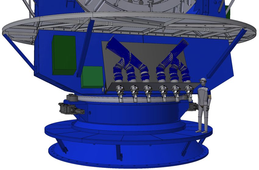
data products with user access interfaces. The instrument allows simultaneous R~5,000 spectral observations of ~1600
targets and R>18,000 observations of ~800 targets. There are several sets of sub-systems performing core functions. The
first are associated with coupling light from the astronomical targets into the optical fibres and include: the VISTA
telescope optics (M1 & M2), the 4MOST Wide Field Corrector and Atmospheric Dispersion Corrector, the Wave Front
Sensors, the Autoguiders, the Fibre Positioner and the fibre Metrology. The second is the Fibre Feed, with the primary
function of transmitting light from the telescope focal surface to the spectrographs. Next the calibration system provides
calibration information, such as flat field and wavelength references. The fourth function is the wavelength dispersion
and detection of the target and calibration light; it includes both the spectrographs and detectors subsystems. There are
Data Management functions including data archiving, spectral extraction, calibration and “quick look”. There are the
Facility Control functions that coordinate the interactions between the different instrument subsystems and monitor the
system performance. Then there are the science operations that manage the observation processes. Finally there is the
safety system that ensures the safety of personal and equipment.

     Figure 2: System Process Model showing the information flow through the 4MOST facility. The orange blocks are
     associated with Science Operations covering pre-observation survey planning (Phase I & II), the blue (and grey)
     with the observations with the instrument at Paranal, the green with Data Management and the post-observations
     data handling (Phase III). The extraction of the higher-level data products is not managed/delivered by the 4MOST
     facility, but by the science teams.
The system-level process and information flow of 4MOST is depicted in Figure 2. The process starts by the Science
Community, who, after using the Survey Planning Tools (Phase I, not depicted), submits Survey Target Catalogues to
the Target Database of the Operations System. The Operations System creates Observing Blocks (OBs, Phase II) that get
executed by the Observing System at the VISTA telescope. The telescope and WFC couple light into optical fibres that
are located at target positions by the Fibre Positioner, these fibres then transmit the target light into the Spectrographs
where it is wavelength dispersed and projected onto the Detectors. The CCD frames of detected photons get stored in the
ESO Archive and are then processed to 1D-calibrated spectra (Spectral Reduction). The high-level data products are
generated (Science Reduction) by the science teams and stored in the Survey Archive by the Data Management System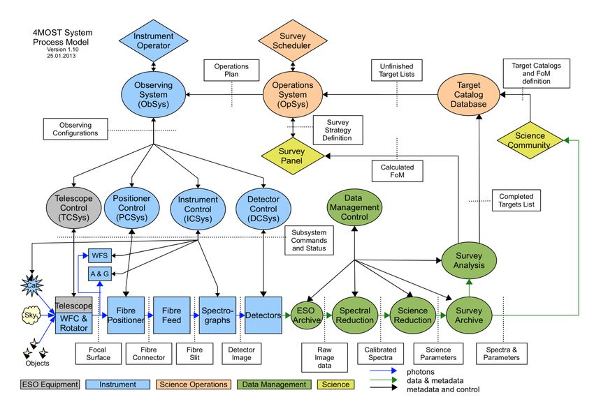
(Phase III). The Data Management also provides Data Quality and Survey Progress information to the Operations
System and the User Community.
The 4MOST facility is a relatively complex system and the project is implementing rigorous system engineering
practices[4]. The instrument systems architecture incorporates several major subsystems and the major hardware
components are shown in Figure 3. The core components of the 4MOST system are discussed in greater details in the
follow sub-sections. In addition, several modifications are required to the telescope including: M2 spider mounts for the
Metrology and Calibration units; upgrade to the Cassegrain rotator; new cable wraps for the fibre feed and Cassegrain
services; additional services below the azimuth floor to support the spectrograph and detector subsystems; modification
to the Telescope Control System (TCS); and of course the removal of IRCAM.

     Figure 3: Layout and location of the 4MOST hardware.
2.1 Operations System
The 4MOST Operations System is the collection of tools and procedures that together enable all 4MOST Phase 1 and 2
activities, driving all 4MOST survey planning functions and tracks performance. It provides survey simulation used to
predict survey outcomes, to optimize the survey strategy, and to prepare for the real survey. The major components are
the 4MOST Facility Simulator (4FS), the Exposure Time Calculator (ETC), the Observer Support Software (OSS), and
the Survey Progress Monitor (SPM). The Science Operations Subsystem does not perform functions at Paranal, but
implements the first steps in the observing process. It forms the interface between the science surveys defined by the
science users and the observing system on the telescope (Phase I and II of observing cycle) and is part of the survey
performance feedback loop. It consists of the Facility Simulator, which by simulating surveys, ensures that targets are
selected and observations scheduled in such a way that all surveys progress as required on all time scales. Users will
have access to Facility Simulator tools (ETC, survey simulating tool) to prepare Phase I proposals. The Operations
System also includes the Observer Support Software that ingests user observing catalogues into the master input
catalogue, creates observing tiles with fibre-target assignment, and schedules and creates Observing Blocks to be
ingested by ESO and transferred to the telescope for observation (Phase II). The system-level process and information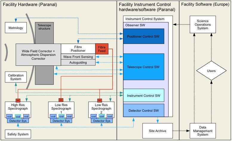
flow of 4MOST starts with the Science Community Survey Planning Tools that submits Survey Target Catalogues to the
Target Database of the Operations System. The Operations System creates Observing Blocks that are executed by the
Observing System at the VISTA telescope.
2.2 Facility System
The 4MOST facility system is not a sub-system of the instrument as such, but consists of the following activities: system
level manufacture, assembly, integration and verification (MAIV); Integrated Logistic Support; Handling & Transport;
Installation and Commissioning; and Operation & Maintenance Training.
System MAIV covers planning and development targeting the period from sub-system Manufacture Item Acceptance
(MIA) at the individual institutes until Preliminary Acceptance Europe (PAE). The system AIV activities will take place
at AIP in Potsdam where the “full functional” subsystem are re-assembled, integrated and verified as a full system. It
should be noted that the installation of 4MOST should be reversible to allow the re-installation and operation of IRCAM.
Integrated Logistic Support shall ensure that all necessary resources (equipment, materials and personal) are available for
the 4MOST facility: system level MAIV; handling and shipping from AIP to Paranal after PAE; the re-integration and
commissioning at VISTA; the operation and maintenance. The latter shall ensure (where possible) that the major
functional part of 4MOST: consists of Line Replaceable Units that can be exchanged with minimal downtime; have
sufficient spare parts; uses standardization; have a useful lifetime of >10 years, with the goal of 99% instrument
availability for the scientific observing time. 4MOST shall deliver any special maintenance equipment needed for
4MOST and support incorporating 4MOST into the computerized maintenance management system at Paranal. The
Logistic Support shall ensure that all required material and personal is available, so that initially the 4MOST consortium
and later the observatory staff are able to operate and maintain the facility.
The system level Handling and Transport activities ensures the handling and transportation of the sub-system to AIP is
compatible with: the requirements for system AIV; the re-integration and commissioning at VISTA; and will follow the
ESO standards.
Installation and Commissioning encompasses the activities that take place at Paranal leading up to Provisional
Acceptance Chile (PAC) and the start of science operations.
Operation & Maintenance Training activities ensure consortium provides adequate training of ESO staff at the
instrument. The training covers the areas: safety, operation, calibration and maintenance. For all these areas according
documentation is supplied.
2.3 Target selection/acquisition

     Figure 4: Left: The WFC assembly with the location of the 4 lenses. Right: The back end of the WFC assembly
     showing layout of the science field (yellow), the HOWFS (light blue), LOWFS (purple) and A&G (green).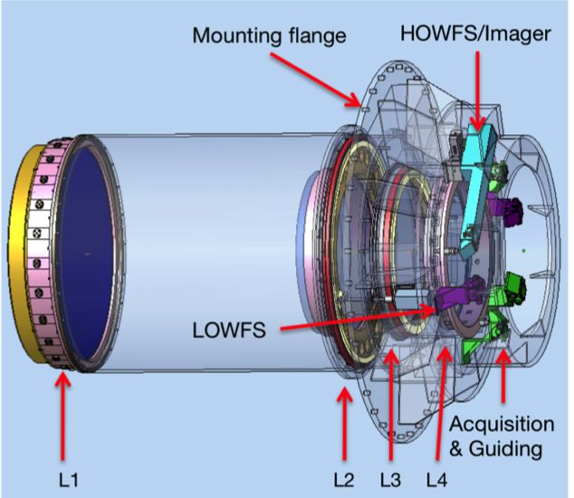
The target selection/acquisition function of 4MOST is spread across several subsystem and includes: the optical system
consists of VISTA Primary Mirror M1, the Secondary Mirror M2 and the Wide Field Corrector (that includes an
Atmospheric Dispersion Corrector) attached to the Cassegrain instrument rotator, that all combined to create an image of
the sky at the telescope focal surface; the target/field Acquisition & Guiding (A&G) units; and the Wave Front Sensors
(WFS) for controlling the M1 shape; the fibre positioner and metrology, that locates the fibres at the target locations on
the focal surface; and the fibre feed.
The current baseline design for the WFC assembly (Figure 4) has an ~2.5° diameter field of view, a maximum residual
dispersion of
The fibre positioner called AESOP (Australian European Southern Observatory Positioner) is based on the tilting spine
concept used for FMOS-Echidna[6] at the Subaru telescope and further developed for the DESpec (“MOHAWK”)[7]
instrument concept. An alternative positioner design[8] that addressed some of the spine tilt and defocus issues of the
Echidna concept was investigated, however, AESOP was selected after the trade off studies were completed. The
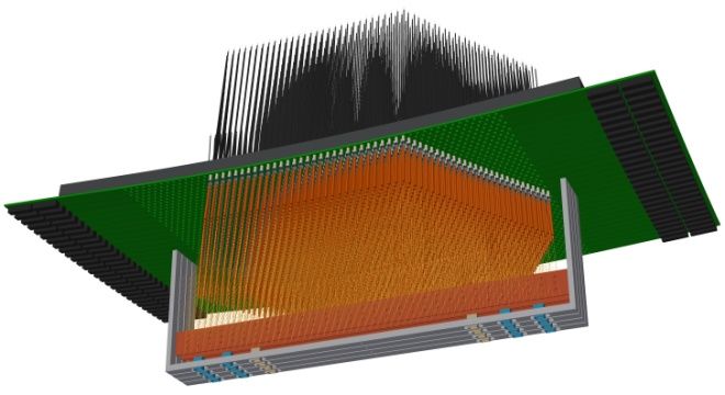
baseline concepts for a spine/actuator module (left) and the fully populated positioner (right) are shown in Figure 5. The
full AESOP structure, including the control electronics is shown in Figure 6.
The precise location of the AESOP fibre spines is determined by the 4MOST metrology system. The metrology unit
determines the locations of each of the AESOP spines in the telescope focal surface and provide AESOP with target
spine position offsets. AESOP then attempts to move the spines to the offset coordinates (in open loop) and iterates with
metrology until the fibre targets are reached. AESOP includes fiducials to act as fixed focal surface reference points. The
current baseline metrology system concept is shown in Figure 7.
Figure 7: The 4MOST positioner metrology system optical concept.
Light is projected back through the science fibres (via back illumination unit located in the each of the spectrographs)
and the full telescope optical train (in the opposite direction to the science target light) to provide detailed fibre position
coordinated via the Metrology cameras mounted above M1, with reference to the AESOP fiducials and the A&G units
(each with there own fiducial markers). The metrology system should determine the location of each of the fibres at the
telescope focal surface to within 5µm in less than 3 seconds.
Once the target light has been efficiently coupled in the optical fibres, the 4MOST fibre feed[9] transports the light to the
spectrographs mounted below the VISTA azimuth floor as shown in Figure 8. The fibre feed includes: the optical fibres
(nominally a 85um core size [~1.35 arcsec] and a nominal123µm polyimide buffer outer diameter); the fibre connectors
at the back of the AESOP positioner; the modularized fibre cable mounted in igus® chain; the fibre de-rotator unit and
altitude fibre cable wraps; fibre strain relief modules; the curved fibre slit assembles; and the fibre health monitor. The
fibre feed is currently estimated to be ~ 15m from spine tip to the lower resolution spectrographs (R>5000) and ~20m to
the higher resolution spectrographs (R>18,000).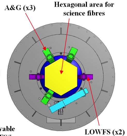
Figure 8: The fibre feed cable run from the AESOP fibre positioner (at the Cassegrain focus of VISTA) to the
     4MOST spectrographs mounted (below azimuth floor) to the VISTA telescope yoke.
2.4 Lower resolution spectrographs (R~5,000)

     Figure 9: The new baseline design lower resolution (R~5,000) spectrographs for 4MOST shown in situ attached to
     the VISTA telescope yoke under the azimuth floor.
The 4MOST lower resolution spectrographs (LRS) were originally design as a two channel system, similar in design to
the low resolution configuration of the WEAVE[11] spectrograph, however, as part of the optimization phase of 4MOST a
three channel design with two spectrographs mounted side by side has been adopted as the baseline design as shown in
Figure 9. The preferred LRS design is design to have a blue channel ~390-530nm, a green channel ~500-690nm and a
red channel ~660-900nm, with each spectrograph able to accommodate ~800 fibres (~1600 in total). Two different three-
channel designs were investigated. The first and preferred LRS design concept (shown in Figure 9), loosely based on the
ESPRESSO design[10], has: a curved fibre slit and can accommodate up to 970 fibres with core size 85µm, fibre
separation ~160µm; an ~f/3.0 off-axis Schmidt collimator; ~200mm beam diameter; three VPH gratings (1674 l/mm
blue, 1298 l/mm green and 993 l/mm red); three ~f/1.7 (fl=340mm) dioptic cameras (5 lenses each), with L2 and L3
containing aspheric surfaces and the last element of each camera acting as the respective dewar (a “standard” ESO
Espresso like design) window; feeding to 6k x 6k flat detectors with 15µm pixels giving an 80% ensquared energy
sampling for the projected fibre image of ~3.3 pixels in the spatial direction and 3.1 – 3.6 pixel in the spectral direction;
and the spectral resolving power of each channel is 5000 to >6840. The design has an elegant layout that allows the
detector dewars to be conveniently mounted relatively side by side for “easy” access.
The second LRS design concept[12] has: a curved fibre slit that can accommodate up to ~750 fibres; an ~f/3.0 on-axis
Schmidt collimator; ~300mm beam diameter; three VPH gratings; three ~f/1.29 double-pass Maksutov style cameras,
and the last element (field lens) of each camera acting as the dewar windows; feeding to 4k x 4k flat detectors with 15µm
pixels giving an 80% ensquared energy sampling for the projected fibre image of ~2.1 pixels; and the spectral resolving
power over the unique coverage of each camera is >5140 everywhere. This design can be reconfigured to high-resolution
mode providing R>18,400 for all of the channels.
Each LRS will accommodate a back illumination system required by the 4MOST metrology system and shutters within a
thermally managed enclosure.
2.5 Higher resolution spectrograph R>18,000.
The 4MOST higher resolution spectrograph/s (HRS) were originally design as a two channel system, one similar in
design to the higher resolution configuration of the WEAVE spectrograph and one based on a vertically mounted camera
design[13], however, as part of the optimization phase of 4MOST two, three channel, spectrograph designs have been
investigated. The adopted baseline design is shown in Figure 10, with the blue channel ~395-440nm, the green channel
~499-556nm and the red channel ~604-673nm. This design has: a curved fibre slit, both in focus and to compensate for
the spectral curvature (slit X curvature radius 332mm) radius and can accommodate up to 1045 fibres with core size
85µm, fibre separation ~176µm; an ~f/3.0 reversed off-axis Schmidt collimator; ~250mm beam diameter; three VPH
gratings (3586 l/mm blue, 2836 l/mm green and 2343 l/mm red); three ~f/1.5 (fl=340mm) cameras (5 lenses each), with
L2 and L3 containing aspheric surfaces and the last element of each camera acting as the respective dewar (a “standard”
ESO Espresso like design) window; feeding to 6k x 6k flat detector with 15µm pixels giving an 80% ensquared energy
sampling for the projected fibre image of ~2.8 pixels in the spatial direction and 2.5 – 3.4 pixel in the spectral direction;
and the spectral resolving power of each channel is ~18,800 to ~21,100. The single HRS will also accommodate a back
illumination system required by the 4MOST metrology system and shutters within a thermally managed enclosure. The
alternative three channel HRS is a reconfigured version of the Maksutov camera LRS deign with the 4k x 4k and 15µm
pixel detector[12].

     Figure 10: (Left) the optical layout of the 4MOST HRS design. (Right) The HRS spectrograph location attached to
     the yoke under the azimuth platform at the front of the VISTA telescope.
2.6 Detector subsystems
The detector system with its cryostats, cooling system and CCD controllers is based on the MUSE[14]&[15]
implementation, with standard ESO CCD controllers that read out the CCD data to the ESO archive at Paranal. This
consists of the detectors, cryostats (Figure 11, left), a continuous flow cooling (CFC) system, and control electronics and
software, all of which are delivered by ESO. Per spectrograph channel this consists of: detector controller Frontend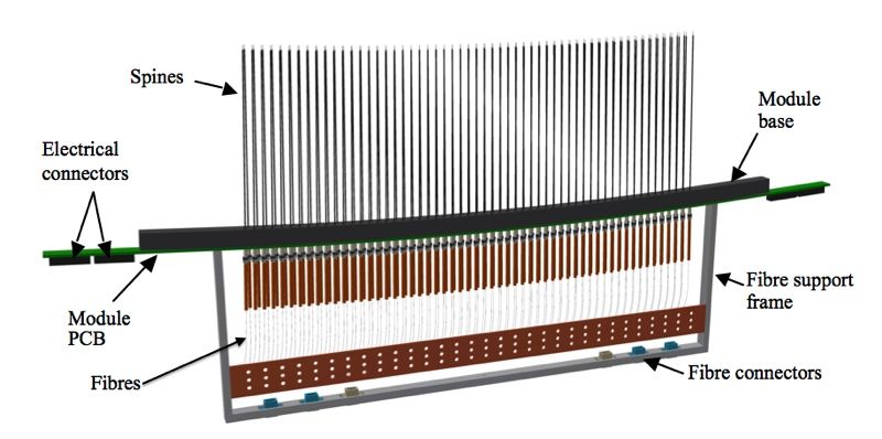
Electronics (NGC DFE), Power Supply (NGC PS), Linux Local Control Unit (LLCU), preamplifier, detector head, CFC
system and cryostat controller (TeePee), all to be delivered by ESO. The baseline LRS and HRS both use a single CCDs
of 6k x 6k array of 15µm square pixels for each channel/camera. In order to accommodate the 6k x 6k detector (versus
4k x 4k for MUSE), some small modifications will be required to the current detector head design (These modifications
are already being addressed by ESPRESSO. The CFC are fed by a central 200 litre LN2 tank (Figure 11, right) mounted
within the telescope pier at the base of the telescope such that it can be readily refilled at the ground floor during daytime
operations.

     Figure 11: (Left) the MUSE detector cryostats design. (Right) The 200 litre LN2 tank for the 4MOST continuous
     flow cooling system is located within the telescope pier under the main body of the VISTA telescope.
2.7 Facility Control System
The Facility Control Subsystem coordinates the interactions between the different subsystems. It consists of Control
Hardware maintaining the physical connections with the subsystems and of Control Software. The Control Software
ensures that all processes run correctly on the instrument to collect and archive data and metadata, and monitors and
safeguards the health and safety of the instrument. It also provides the Observing Software System that interfaces to
operators and engineers. The control system for the 4MOST system is divided into six main control systems: the
Instrument Control System (ICS1); the Target Acquisition System (ICS2); the Telescope Control System (TCS); the
New Generation detector Controller (NGC); the Observation Handling (OH) that manages the global control of the
instrument; and the ESO Archive System that takes care of the science data. Workstations (WS) with corresponding
control software are used to accomplish given tasks. Local Control Units (LCUs) and Programmable Logical Controllers
(PLCs) are used to transmit the commands to the respective components.
The instrument software runs on the WS and is responsible for the control of all hardware devices (lamps, motors,
sensors etc) in 4MOST. In addition, it controls the sequence of actions that are necessary for observations, calibrations,
and maintenance. The software will obey the requirements of "VLT Instrumentation Software Specification" and "INS
Common Software Specification". ESO is currently in transition from the traditional VLT VME/VxWorks Local Control
Units (LCU) environment to Fieldbus Extension as is assumed to be the baseline for the 4MOST facility control.
4MOST will split control into two parts (from an instrument-control point of view). The ICS1 manages the instrument
relevant functions i.e. Spectrographs, Calibration Unit and the A&G, WFS, ADC, Back-Illumination, as well as the
interaction with telescope and detectors, and the overall control. ICS2 (also call Target Acquisition) manages all
functions, corresponding to the positioner, metrology unit and fibre feed. Whether or not ICS1 and ICS2 can be run on
the same WS will be assessed in the next project phase. The cryostats are not controlled by ICS1, they are rather
independent and controlled manually in the dome. ICS1 just monitors the sensors, connected to the Vacuum and
Cryogenics System (VCS). A standard ESO NGC System controls the science detectors in the spectrographs. All
telescope related functionality is managed by the TCS, including the A&G and WFS Technical CCDs (TCCDs).
2.8 Data Management
The Data Management Subsystem (DMS) takes the raw data from the ESO archive and performs a quick look analysis
(Level 0) for immediate Data Quality feedback to the observer. Offsite, the DMS uses the raw data and carries out a
spectral extraction and calibration of the individual spectra (Level 1, see Figure 12, right). The DMS next performs
Science Analysis (Level 2) on the extracted spectra to derive higher-level science products (radial velocities, stellar
parameters, element abundances, redshifts, etc.). The DMS provides survey analysis tools to ensure that all surveys are
progressing as expected. The DMS also encompasses Archive and Distribution tools. The archive will have a VO
compliant interface layer to ensure that all products can be accessed via VO compliant protocols.
Figure 12: Left: Data Flow in the Data Management System, Right: Level 1 Data Flow
2.9 Calibration Subsystem
The Calibration Subsystem provides Flux Calibration by obtaining spectra of broadband light fed into the fibres. The
Wavelength and Resolution Calibration is obtained by taking spectra of light with narrow, well-characterized emission
lines into all science fibres, as well as feeding such light in dedicated calibration fibres permanently intermixed with the
science fibres in the spectrograph. Goal is to make 4MOST stable enough such that most calibrations can be done during
daytime. The calibration illumination unit shall provide light that is nearly uniformly distributed over the focal plane.
The difference between the illumination pattern from the illumination unit and the pattern from sky flat fields shall be no
larger than 10%. The illumination shall be stable such that it does not significantly contribute to the final error in sky
subtraction, which means it shall be stable to within 1% during one night. The Calibration Unit shall provide at the fibre
focal plane 1) a continuum flatfield with a flux per pixel > 10 phot/sec-pix (SNR > 20 for 30 second exposure) and 2) a
spectral flatfield with a flux per line (phot/sec) > 100 phot/sec-pix (SNR > 100). The calibration system consists of two
main components: the lamp cabinet including optical fibres and the calibration unit that are attached to the M2 spider
2.10 Safety Subsystem
The Safety Subsystem assures there is no unacceptable safety risk of harm for the personnel, the 4MOST facility, the
telescope and the surrounding environment during all life cycle stages of 4MOST. The Safety Subsystem will be
operational even when the Facility Control Subsystem is not functioning. The 4MOST Safety System will be the
interface between the instrument and the Central Alarm System (CAS) infrastructure. Predefined alarms will be routed
through an Alarm Connection Point (ACP), following the Alarm System protocols/standards for the Paranal
Observatory.3. SUMMARY
4MOST is a wide-field, high-multiplex spectroscopic survey facility under development for the European Southern
Observatory (ESO) and is due for installation at the VISTA telescope in 2019. The main science drivers for 4MOST are
galactic archaeology, high-energy physics, galaxy evolution and cosmology that will be performed during 5-year public
surveys. The parallel Survey strategy will provide multiple target types in each exposure and resulting in more than 25
million spectra of targets spread over a large fraction of the Southern sky. 4MOST will have a 2.5 degree diameter field-
of-view with ~2400 fibres configured by the AESOP fibre positioner, ~1600 fibres are fed to two spectrographs with
resolution R~5000 and ~800 fibres are fed to a single spectrograph with R>18,000. Both spectrographs are fixed-
configuration, three-channel designs.
4. ACKNOWLEDGMENTS
We gratefully acknowledge the financial support of the German Federal Ministry of Education and Research (BMBF)
through the Verbundforschung (grant no. 05A11BA3) and the Program Unternehmen Region (grant no. 03Z2AN11).
5. REFERENCES
[1] de Jong, R. S., Bellido-Tirado, O.; Chiappini, C.; Depagne, E., Haynes, R., et al., “4MOST: 4-metre multi-
object spectroscopic telescope,” SPIE 8446, 84460T–15, 2012.
[2] Schnurr, O., Walcher, C.J., Chiappini, C., Schwope, A.D., Bellido-Tirado, O., et al., “From spec to specs:
requirements for 4MOST,” SPIE 9150, 9150–46 (in these proceedings), 2014.
[3] Winkler R., Haynes, D.M., Bellido-Tirado, O., Xu, W., and Haynes, R., “TOAD: a numerical model for the
4MOST instrument,” SPIE 9150, 9150-28 (in these proceedings), 2014.
[4] Bellido-Tirado, O., Haynes, R., de Jong, R. S., Schnurr, O., Walcher, C. J., and Winkler, R., “Systems
engineering implementation in the conceptual design phase of 4MOST,” SPIE 9150, 9150–45 (in these
proceedings), 2014.
[5] Gillingham, P. and Saunders, W., "A wide field corrector with loss-less and purely passive atmospheric
dispersion correction," SPIE 9151, 9151-230 (in these proceedings), 2014.
[6] Brzeski, J.K., Gillingham, P., Correll, D., Dawson, J. Moore, A.M., et al., “Echidna: the engineering
challenges,” SPIE 5492, doi:10.1117/12.550963, 2004.
[7] Saunders, W., Smith, G., Gilbert, J., Muller, R., Goodwin, M., Staszak, N., Brzeski, N., Miziarski, S., Colless,
M., “MOHAWK: a 4000-fiber positioner for DESpec,” SPIE 8446, 84464W, doi:10.1117/12.925724, 2012.
[8] Saviauk, A. Dionies, F., de Jong, R., Haynes, R., Parry, I.R., “The fiber positioner for 4MOST: exploration of
an alternative R-θ design,” SPIE 9151, 9151-187 (in these proceedings), 2014.
[9] Haynes, D., Winkler, R., Saviauk, A. Haynes, R., Barden, S.C., et al., “4MOST Fiber Feed Concept Design,”
SPIE 9150, 9147-235 (in these proceedings), 2014.
[10] Pepe, F.A., Cristiani, S., Lopez, R.R., Santos, N.C., et al., “ESPRESSO: the Echelle spectrograph for rocky
exoplanets and stable spectroscopic observations,” SPIE 7735, 77350F, doi:10.1117/12.857122, 2010.
[11] Dalton, G., Trager, S.C., Abrams, D.C., Carter, D., Bonifacio, P., et al., “WEAVE: the next generation wide-
field spectroscopy facility for the William Herschel Telescope,” SPIE 8446, 84460P, doi: 10.1117/12.925950,
2012.
[12] Saunders, W., "Efficient and affordable catadioptric spectrograph designs for 4MOST and Hector," SPIE 9147,
9147-223 (in these proceedings), 2014.
[13] Mignot, S.B., Cohen, M., Horville, D., Amans, J.-P., Jagourel, P., ”High resolution spectrograph for the
4MOST facility,” SPIE 8446, doi10.1117/12.925958, 2012.
[14] Bacon, R., Accardo, M., Adjali, L., Anwand, H., Bauer, S., et al., “The MUSE second-generation VLT
instrument,” SPIE 7735, doi: 10.1117/12.856027, 2010.
[15] Lizon, J.L., Accardo, M., Gojak, D., Reiss, R., and Kern, L., “Vacuum and cryogenic system for the MUSE
detectors,” SPIE 8446, dio:10.1117/12.924650, 2012.You can also read