The Large Hadron Collider
←
→
Page content transcription
If your browser does not render page correctly, please read the page content below
34th SLAC Summer Institute On Particle Physics (SSI 2006), July 17-28, 2006

  The Large Hadron Collider
             Lyndon Evans
             CERN – European Organization for Nuclear Research, Geneva, Switzerland

  1. INTRODUCTION

       The Large Hadron Collider (LHC) at CERN is now in its final installation and commissioning phase. It is a two-ring
  superconducting proton-proton collider housed in the 27 km tunnel previously constructed for the Large Electron
  Positron collider (LEP). It is designed to provide proton-proton collisions with unprecedented luminosity (1034cm-2.s-1)
  and a centre-of-mass energy of 14 TeV for the study of rare events such as the production of the Higgs particle if it
  exists. In order to reach the required energy in the existing tunnel, the dipoles must operate at 1.9 K in superfluid
  helium. In addition to p-p operation, the LHC will be able to collide heavy nuclei (Pb-Pb) with a centre-of-mass energy
  of 1150 TeV (2.76 TeV/u and 7 TeV per charge). By modifying the existing obsolete antiproton ring (LEAR) into an
  ion accumulator (LEIR) in which electron cooling is applied, the luminosity can reach 1027cm-2.s-1.
       The LHC presents many innovative features and a number of challenges which push the art of safely manipulating
  intense proton beams to extreme limits. The beams are injected into the LHC from the existing Super Proton
  Synchrotron (SPS) at an energy of 450 GeV. After the two rings are filled, the machine is ramped to its nominal energy
  of 7 TeV over about 28 minutes. In order to reach this energy, the dipole field must reach the unprecedented level for
  accelerator magnets of 8.3 T. This high field can only be achieved using “conventional” and affordable superconducting
  material (NbTi), by cooling the magnets in superfluid helium at 1.9 K. The cryogenic equipment needed to produce the
  100 tons or so of superfluid helium is unprecedented in scale and complexity.
       The tunnel diameter in the regular arc is only 3.8 m, insufficient for the installation of two separate rings. The two
  rings are therefore incorporated into a single magnetic structure with two sets of coils in a common yoke and cryostat.

  2. MACHINE PERFORMANCE

       At nominal luminosity, the energy stored in each beam is more than 350 MJ (equivalent to 80 kg of TNT). This is
  more than two orders of magnitude in stored energy, and three orders of magnitude in energy density (due to the very
  small beam emittance) than in any other previous machine (Figure 1). It imposes unprecedented conditions on the
  reliability of the safety systems which must abort the beams cleanly if necessary as well as on the collimation systems
  which protect the machine and detectors from halo particles.

L003                                                             1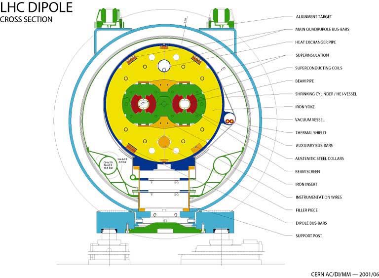
34th SLAC Summer Institute On Particle Physics (SSI 2006), July 17-28, 2006

  Figure 1: a. Energy stored in the accelerator beam, as a function of beam momentum. At less than 1% of nominal
  intensity LHC enters new territory.

  Figure 1: b. Stored energy density as a function of beam momentum. Transverse energy density is a measure of damage
  potential and is proportional to luminosity.

       The number of events per second generated by beam-beam collisions for a given process is given by:
                                                              N = Lσ
  where σ is the cross section for the process in question and L is the luminosity. For the study of very rare events the
  luminosity must be as high as possible. The luminosity depends only on beam parameters and can be written for a
  Gaussian beam profile as:

                                                          N b2 n f r γ
                                                       L=
                                                          4π ε n β *
  where Nb is the number of particles per bunch, n the number of bunches per beam, fr the revolution frequency (11.245

  kHz), γ the relativistic gamma factor, εn the normalized transverse emittance and      β*   the beta function at the collision

L003                                                            2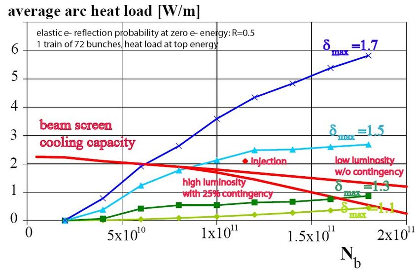
34th SLAC Summer Institute On Particle Physics (SSI 2006), July 17-28, 2006
point. As well as the rare hard collisions between particles, the particles in one beam experience the global
electromagnetic field of the other beam (the beam-beam interaction). This force is very nonlinear and gives rise to
unwanted effects if not limited to as small a value as possible. Therefore the bunches must have a crossing angle in
order to limit the beam-beam force to the colliding bunches. This produces a geometrical luminosity reduction factor F
given by:
⎛θ σ ⎞
F = 1 / 1 + ⎜ C *Z ⎟
⎝ 2σ ⎠
where θc is the full crossing angle at the interaction point (IP), σz the rms bunch length and σ* the transverse rms beam
size at the crossing point.
Table 1 shows the main parameters required to reach a peak luminosity of 1034 cm-2 s-1 for proton-proton collisions at
14 TeV centre-of-mass. It can be seen from the table that for the first time in a hadron machine, the synchrotron
radiation at top energy is not negligible. At 3.6 kW per beam it is still very small compared with lepton storage rings
and has no influence on the design of the radio frequency system, but this power is radiated into a cryogenic
environment and strongly influences the design of the vacuum and cryogenic systems.
Table 1: Performance parameters.
• Circumference 26.7 km
• Beam energy at collision 7 TeV
• Beam energy at injection 0.45 TeV
• Dipole field at 7 TeV 8.33 T
• Luminosity 1034 cm-2.s-1
• Beam current 0.56 A
• Protons per bunch 1.1x10¹¹
• Number of bunches 2808
• Nominal bunch spacing 24.95 ns
• Normalized emittance 3.75 μm
• Total crossing angle 300 μrad
• Energy loss per turn 6.7 keV
• Critical synchrotron energy 44.1 eV
• Radiated power per beam 3.8 kW
• Stored energy per beam 350 MJ
• Stored energy in magnets 11 GJ
• Operating temperature 1.9 K
2.1. Machine Layout
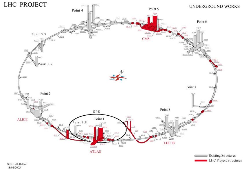
The basic layout of the LHC follows the LEP tunnel geometry and is shown in Figure 2. The machine has eight arcs
and straight sections. Each straight section is approximately 528 m long. Four of the straight sections house the LHC
detectors whilst the other four are used for machine utilities, radio frequency, collimation and beam abort. The two
high luminosity detectors are located at diametrically opposite straight sections. The ATLAS detector is located at Point
1 and CMS at Point 5, which also incorporates the small angle scattering experiment TOTEM. Two more detectors are
L003 3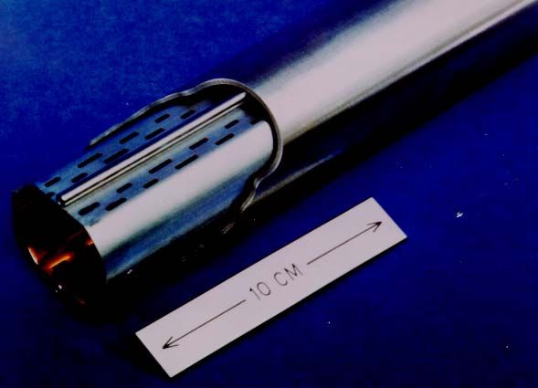
34th SLAC Summer Institute On Particle Physics (SSI 2006), July 17-28, 2006

  located at Point 2 (ALICE) and at Point 8 (LHCb), which also contain the injection systems for the two rings. The
  beams only cross from one ring to the other at these four locations.

                                                        Figure 2: LHC layout.

       In order to leave enough space for the LHCb spectrometer magnet in the already existing experimental cavern at
  Point 8, the interaction point at this location is shifted by 11.25 m towards Point 7. Bunches with the nominal 25nsec
  separation collide at all four crossing points simultaneously. However, because of this displacement, the only other
  bunch separation with simultaneous collisions in all four detectors is 75nsec. For early commissioning, this bunch
  separation is interesting because there is no possibility of electron cloud buildup (see below) and the number of long-
  range beam-beam interactions is reduced, simplifying early machine operation. The 25 GeV proton synchrotron (the
  first circular machine in the injector chain), where the LHC bunch structure is generated, has therefore been equipped
  with the means to provide either of these two bunch spacings.
       Straight sections at Points 3 and 7 contain two collimation systems for capturing stray particles. Point 3 is designed to
  capture off-momentum particles (momentum collimation) and Point 7 for removing the beam halo (betatron
  collimation). Point 4 contains the two Radio Frequency systems, one independent system for each beam operating at
  400 MHz, twice the frequency of the LHC injector. Finally, Point 6 contains the two beam abort systems which will
  allow the beams to be extracted safely and dumped onto external absorbers.
       The regular LHC lattice was designed to maximize the amount of bending power in the arc by making the dipoles as
  long as reasonably possible. This minimizes the amount of dead space between interconnects as well as the number of
  dipoles to be manufactured, tested and interconnected. After careful optimization, the dipole length was chosen to be
  14.2 m (magnetic), 15 m overall with 23 regular lattice periods per arc. Each period is 106.9 m long and is made up of

L003                                                              4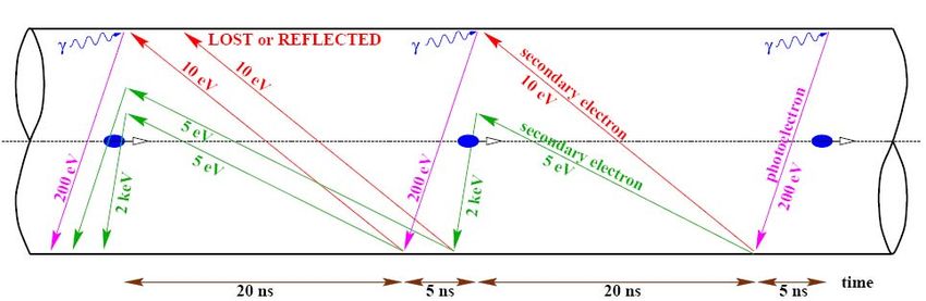
34th SLAC Summer Institute On Particle Physics (SSI 2006), July 17-28, 2006

  six dipoles and two short straight sections each of 6.6 m length containing the main quadrupoles and lattice correctors.
  The two apertures of ring 1 and ring 2 are separated by 194 mm. Both dipole apertures are connected in series whereas
  the quadrupoles are powered in two families, all focusing quadrupoles of rings one and two in series and likewise for
  the defocusing quadrupoles.
       The transition from the regular arc contains a dispersion suppressor consisting of two perturbed lattice periods. The
  purpose of the dispersion suppressor is threefold:
       -     adapt the LHC reference orbit to the geometry of the tunnel,
       -     cancel the horizontal dispersion generated in the arc and by the separation and recombination dipoles,
       -     help with the matching of the beams between the arcs and straight sections.
       A generic design of a dispersion suppressor can be made using standard arc cells with missing dipoles and dipoles of
  different length to those in the arc. However, due to the constraints imposed by the geometry of the existing tunnel and
  the economy of having only one standard dipole length, the dispersion can only be fully cancelled by individual
  powering of the quadrupoles in the dispersion suppressor cells. These quadrupoles also provide additional parameters
  for matching the insertion optics.
       The short straight sections in the arcs contain the main quadrupoles and also the correction sextupoles for
  chromaticity control and the orbit correction dipoles. Depending on their location, they can also contain trim normal or
  skew quadrupoles or Landau damping octupoles.
       The optics of the long straight sections differ according to their functionality. At Points 1 and 5 in the high luminosity
  insertions the small beta (0.5 m) at the collision point is generated with the help of a quadrupole triplet assembly. At
  Points 2 and 8, the optics at the 450 GeV injection level must allow beam injection whereas at top field the beams must
  be focused to a moderate beta. At the utility insertions the optics is tailored to their functionality. Details of the optics in
  the various insertions can be found elsewhere [1].

  2.2. Main Hardware Systems

       The main hardware systems include magnets, vacuum, cryogenics, radio frequency, power converters, injection and
  extraction equipment, beam instrumentation, collimation and controls, far too numerous for an article of this size.
  Details can be found in the LHC Design Report [1]. Only a few selected systems of general interest will be treated here.

  2.3. Magnets

       The LHC contains more than 7000 superconducting magnets ranging from the 15 m long main dipoles to the 10 cm
  long octupole/decapole correctors inside the dipole cold masses as well as more than 100 conventional warm magnets
  not counting the 500 or so conventional magnets in the two 2.6 km long transfer lines between the SPS and the LHC.
  The most challenging are the superconducting dipoles and the quadrupoles in the arcs, dispersion suppressor and
  matching regions.
       The three large superconducting accelerators operating today, the Tevatron (FNAL), HERA (DESY) and RHIC
  (BNL) all use magnets made with classical Nb-Ti superconductor cooled with supercritical helium at a temperature
  slightly above 4.2 K. In each case, the nominal field is below or around 5 T. In order to increase the field to above 8 T,
  two possibilities exist today.

L003                                                              5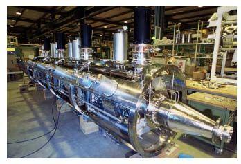
34th SLAC Summer Institute On Particle Physics (SSI 2006), July 17-28, 2006

       Figure 3 shows the critical current density of two superconductors available commercially today. The Nb-Ti
  conductor at 4.5 K has a critical current density that is too low to reach the LHC objective. The other commercially
  available conductor made from Nb3Sn gives a shift of about 3 T upwards at 4.5 K and could be used for such high field
  magnets. However, Nb3Sn superconductor is a very brittle material and cannot be used to wind magnet coils. Instead,
  the coils have to be wound before the heat treatment needed to produce the superconducting state, which requires them
  to be heated to over 600 degrees for many tens of hours. Whilst this may be reasonable for a small number of
  specialized magnets, it is clearly not feasible for a large series.

                                       Figure 3: Critical current density of superconductors.

       The other way to high fields is to cool conventional superconductor to lower temperature. It can be seen from Figure
  3 that Nb-Ti cooled to 1.8 K gives the same 3 T shift as Nb3Sn. This is a much more economical way to getting the high
  fields needed. However, it does not come without difficulties. First of all, there is a phase transition in helium at 2.17 K
  when the liquid becomes superfluid. The advantages and disadvantages of this are discussed below. In addition, the heat
  capacity of the superconductor decreases by an order of magnitude between 4,5 and 1.8 K, so for a given heat inleak
  into the cable, for example due to small movement under the very high electromagnetic force or heating due to beam
  loss, the temperature rise is much higher, making the magnets much more sensitive to quenches. However, the
  superfluid helium can help if the coils are properly engineered.
       A twin aperture dipole consists of two dipoles in a common iron yoke (Figure 4). The two coils are clamped with
  austenitic steel collars with very low permeability surrounded by a yoke of low carbon steel which carries the magnetic
  flux. Figure 5 shows the flux plot as computed for the whole structure of the main dipole.
       The requirement that the field must be in the opposite directions in the two apertures (for a proton-proton collider)
  ensures that there is no saturation of the central part of the yoke. The stored energy of 500 kJ/m in the magnet at
  nominal field requires active quench protection. If a quench is detected, the whole coil is made resistive by firing a
  capacitor bank into resistive strips (quench heaters) built into the coil. The current is then diverted through a diode until
  the power supply can be switched off.

L003                                                             6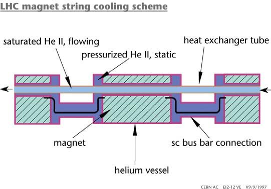
34th SLAC Summer Institute On Particle Physics (SSI 2006), July 17-28, 2006

       The cross section of one quarter of a coil is shown in Figure 6. The coil is wound in two layers in six blocks separated
  with copper wedges. The geometry of the conductor distribution has been carefully optimized to achieve as pure a
  dipole field as possible. The optimum geometry, which minimizes the higher harmonics of the field distribution, has
  been computed using a genetic algorithm. Once the coil geometry has been fixed, then it is very important to keep it
  constant during the whole series production.

                                                   Figure 4: Dipole cross-section.

                                                    Figure 5: Flux plot in dipole.

L003                                                             7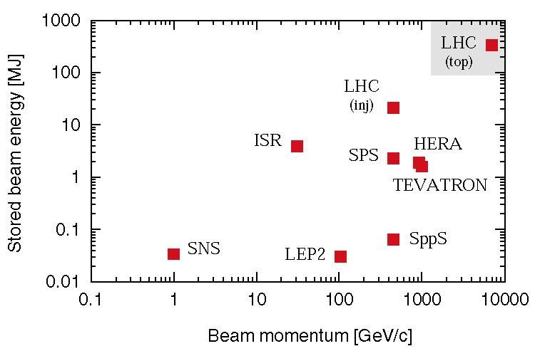
34th SLAC Summer Institute On Particle Physics (SSI 2006), July 17-28, 2006

              Figure 6: Distribution of conductors in dipole coil. The coil blocks are separated by four copper wedges.

       Equipment has been provided to the magnet manufacturers to allow the measurement of the field harmonics in the
  collared coil before assembly into the yoke. In this way, a tight quality control can be kept throughout the
  manufacturing run. Figure 7 shows the sextupole component of the field in about 1000 produced magnets. At the
  beginning of production it was necessary to make two small iterations on the geometry of the copper wedges in order to
  bring the harmonics inside the required control limits.

                         Figure 7: Sextupole component (b3) of magnetic field in 1000 of the 1232 dipoles.

       Apart from the field quality, it is also important to keep the integrated transfer function (effectively the bending angle
  for a given current) inside tight limits and identical for all three manufacturers. Too large dispersion in bending angle
  would result in very large orbit distortion which would be difficult to correct and variation in the mean for the three

L003                                                              8
34th SLAC Summer Institute On Particle Physics (SSI 2006), July 17-28, 2006
manufacturers would require that they are sorted into different octants depending on the manufacturer. Figure 8 shows
what has been achieved for 1000 dipoles produced. The dispersion is much smaller than specified and the variation in
the mean is so small that magnets from the three manufacturers can freely be mixed, simplifying enormously the
logistics.
Figure 8: Integrated bending strength measured over 1000 dipoles from three manufacturers.
The main arc quadrupoles, 3.25 m long, are made with the same superconducting cable as the outer layer of the
dipoles. Since the electromagnetic forces are much less and the geometry is more suited, the coils have separate
austenitic steel collars instead of the combined collar structure of the dipoles. Each quadrupole is integrated into a Short
Straight Section (SSS), each containing a sextupole for chromaticity correction and a closed orbit correction dipole.
Depending on its position in the arc, a SSS can also contain a trim quadrupole or a Landau octupole.
In addition to the main arc magnets, the LHC contains many more elements for correction of dipole imperfections,
matching of the optics and in the final focus. Table 2 gives a full list of all superconducting magnets, their number and
function.
Table 2: List of superconducting magnets and their function.
Type Number Function
MB 1232 Main dipoles
MQ 392 Arc quadrupoles
MBX/MBR 16 Separation & recombination dipoles
MSCB 376 Combined chromaticity & closed orbit correctors
MCS 2464 Sextupole correctors for persistent currents at injection
MCDO 1232 Octupole/decapole correctors for persistent currents at injection
MO 336 Landau damping octupoles
MQT/MQTL 248 Tuning quadrupoles
MCB 190 Orbit correction dipoles
MQM 86 Dispersion suppressor & matching section quadrupoles
MQY 24 Enlarged-aperture quadrupoles in insertions
MQX 32 Low-beta insertion quadrupoles
L003 934th SLAC Summer Institute On Particle Physics (SSI 2006), July 17-28, 2006
2.4. Cryogenics
The LHC magnets are cooled with pressurized superfluid helium, which has some interesting properties that make it a
unique engineering material. Best known is its very low bulk viscosity which allows it to permeate the smallest cracks.
This is used to advantage in the magnet design by making the coil insulation porous and enabling the fluid to be in
contact with the strands of the superconductor. It also has a very large specific heat, 100,000 times that of the
superconductor per unit mass and 2000 times per unit volume. Finally the thermal conductivity peaks at 1.9 K (Figure
9) and is approximately 1000 times higher than that of cryogenic grade OFHC copper. The helium in the coil can
therefore make up for the very low specific heat of the conductor at this temperature by helping to absorb unwanted
thermal loads and transporting them efficiently outside the coil.
2000
Helium II
K(T,q& ) = q& −2.4 ⋅ Y(T)
1500 dT q& 3.4
=
dX Y(T)
Y(T) ± 5%
q& in W / cm2
1000 T in K
X in cm
500
Tλ
OFHC copper
0
1.3 1.4 1.5 1.6 1.7 1.8 1.9 2 2.1 2.2
T [K]
Figure 9: Thermal conductivity of HeII
The most usual method of making superfluid helium in the laboratory is by pumping on the helium bath. Figure 10
shows the phase diagram of helium in the region of the point of the phase transition (the lambda point). Pumping on the
bath reduces the pressure and at around 50 mbar and at a temperature of 2.17 K it crosses the lambda point. Further
reduction of the pressure to 15 mbar lowers the temperature to 1.9 K.
L003 1034th SLAC Summer Institute On Particle Physics (SSI 2006), July 17-28, 2006
10000
SOLID
1000
CRITICAL POINT
λ line
P [kPa] HeII HeI
100
Pressurized He II
GAS
10
Saturated He II
1
1 10
T [K]
Figure 10: Phase diagram of Helium
The magnets themselves are cooled in a bath of superfluid at atmospheric pressure. This is achieved through a linear
heat exchanger traversing each 107 m period of magnets (Figure11) containing superfluid at 15 mbar pressure, cooling
the helium in the magnets at 1 bar to the same temperature as the saturated superfluid inside the heat exchanger. One
big advantage of this system is that there is no problem with the bad dielectric strength of gaseous helium since the coil
is permanently in liquid.
Figure 11: Linear heat exchanger
The machine is cooled using 8 cryogenic plants, each of 18 kW capacity at 4.5 K, located in pairs at the even points
except for one singularity at Point 2. Figure 12 shows the cryogenic architecture at an even point. Four of the
refrigerators are recuperated and upgraded from LEP, the other four are new.
L003 1134th SLAC Summer Institute On Particle Physics (SSI 2006), July 17-28, 2006
Figure 12: Cryoplant architecture at an even point
The LEP refrigerators have their cold box split between surface and tunnel level whereas the new plants are located
on the surface. At the tunnel level, the conventional refrigerators are supplemented by cold compressors. These multi-
stage axial centrifugal compressors (Figure 13) pump the cold helium gas, producing the 15 mbar pressure in the linear
heat exchangers inside the magnets in order to produce the primary superfluid. The connection to the magnets is made
through a cryogenic distribution line running in the tunnel parallel to the machine. An interconnect box allows the
plants to be used in the arc either side of the even point or if needed, for the full power of both plants to be used in one
arc.
L003 1234th SLAC Summer Institute On Particle Physics (SSI 2006), July 17-28, 2006
Figure 13: Cold compressor impeller stages.
Using a single cryogenic plant boosted with a liquid nitrogen precooler, a sector can be cooled down in less than 15
days. By coupling two plants to the same octant, this time can be reduced by a factor of two. Warming of a sector takes
about the same time.
2.5. The Radiofrequency Acceleration System
The RF system is located at Point 4. Two independent sets of cavities operating at 400 MHz (twice the frequency of
the SPS injector) allow independent control of the two beams. The superconducting cavities are made from copper on
which a thin film of a few microns of Niobium is sputtered onto the internal surface. In order to allow for the lateral
space, the beam separation must be increased from 194 mm in the arcs to 420 mm. In order to combat intrabeam
scattering (see below), each RF system must provide 16 MV during coast whilst at injection 8 MV is needed. For each
beam there are 8 single cell cavities, each providing 2 MV, with a conservative gradient of 5.5 MV/m. The cavities are
grouped into two modules per beam, each containing four cells (Figure 14). Each cavity is driven by an independent RF
system, with independent klystron, circulator and load. Although the RF hardware required is much smaller than LEP
due to the very small synchrotron radiation power loss, the real challenges are in controlling beam loading and RF
noise.
L003 1334th SLAC Summer Institute On Particle Physics (SSI 2006), July 17-28, 2006
Figure 14: Four-cavity module during assembly
2.6. The Vacuum System
The LHC presents several original requirements compared with classical vacuum systems. It has to ensure adequate
beam lifetime in a cryogenic system where heat input to the 1.9 K helium circuit must be minimized and where
significant quantities of gas can be condensed on the vacuum chamber. The main heat sources are:
- Synchrotron light radiated by the beam at high energy (0.2 W.M-1 per beam, with a critical energy of about
44 eV;
- Image currents (0.2 W.M-1 per beam);
- Energy dissipated by the development of electron clouds (see below);
- Energy loss by nuclear scattering (30 mW.M-1 per beam).
In order to remove the heat from all these processes but the last with high thermodynamic efficiency, the 1.9 K cold
bore of the magnets is shielded with a beam screen cooled to between 5 and 20 K (Figure 15). This beam screen is
perforated with about 4% of the surface area to allow the cold bore of the magnets at 1.9 K to act as a distributed
cryopump, allowing gas to be condensed on the cold bore surface protected against desorption by bombardment with
synchrotron radiation photons.
L003 1434th SLAC Summer Institute On Particle Physics (SSI 2006), July 17-28, 2006
Figure 15: LHC beam screen
For roughly 3 km of the 27 km circumference, mainly in the long straight sections, the vacuum chambers are at room
temperature, requiring a low residual pressure without the benefit of the distributed cryopumping. As a spin-off of the
development of sputtering technology for superconducting cavities a new getter material (TiZrV) has been developed
which can be sputtered on the internal surface of the copper vacuum chambers and can be activated at the very low
temperature of 200 degrees (conventional getters require activation at 600 degrees). When activated, the chamber wall
itself becomes a distributed pump, producing very low residual pressure and at the same time a very low secondary
emission yield, preventing the buildup of an electron cloud. All warm chambers, including those inside the detectors,
are treated in this way.
2.7. Accelerator Physics Issues
More than 30 years of accumulated experience from the first hadron collider, the Intersecting Storage rings as well as
the proton-antiproton colliders at CERN and FNAL and the superconducting storage rings at BNL and DESY has gone
into the LHC design. In the following chapters, the different effects that could limit machine performance and the
remedies adopted are described.
2.8. Dynamic Aperture
In superconducting magnets of the type used in the LHC, the field quality is determined by the precision of the
positioning of the superconductor and not by the geometry of the iron yoke, so it can never be as good as in
conventional magnets. It has been shown by experience in the different superconducting machines and by particle
tracking that the aperture inside which particle orbits are stable is much smaller than the physical aperture of the beam
pipe. This is called the dynamic aperture and is limited by a complex interplay between the unwanted higher field
harmonics due to magnet imperfections. Sophisticated computer codes have been developed to track particle orbits
around virtual machines with distributed random and systematic imperfections. And these results are used to define
L003 1534th SLAC Summer Institute On Particle Physics (SSI 2006), July 17-28, 2006
maximum systematic and random deviations of each field multipole. It was from this work that the control limits for the
sextupole component of the dipole field shown in Figure 7 were derived. Even with present day computers it is not
possible to perform full scale simulation over a large number of virtual machines over 4x10⁷ turns, which corresponds
to 1 hour of storage time. The dynamic aperture obtained from tracking of existing machines is always too optimistic
when compared to experiment by 20% or more. For the LHC, in order to insure a dynamic aperture of 6 sigms it has
been decided that the tracked dynamic aperture over 106 turns should be a factor of 2 larger. These results have been
used to supply the tables of allowed multipole errors to the magnet builders.
Since the dynamic aperture depends strongly on the horizontal and vertical tunes, the tracking studies are also used to
find the best working points.
2.9. The Beam-Beam Interaction
When the beams are brought into collision, a much stronger nonlinearity than the magnet imperfections comes into
play. It is called the beam-beam interaction and is caused by the force due to the electromagnetic field of one beam on
the particles in the other beam. It produces two main effects.
The first is to cause a variation of the tune with amplitude. This means that the beam does not occupy a point on the
Qh, Qv tune diagram but produces an extended “footprint” The second effect is that because of the periodic nature of
the force (particles experience a delta function kick on each revolution) it excites nonlinear resonances which can
strongly limit the beam lifetime. Figure 16 is an example of a tune scan made many years ago on the SPS proton-
antiproton collider. The lower figure shows the tune diagram with nests of 10th, 7th and 11th order resonances. The
beams are scanned across these resonances in steps, the lines corresponding to each scan position being intended to
indicate approximately the size of the footprint. The upper diagram shows a chart recorder output of the intensity decay
of the beams for each position in tune space. In this experiment, the antiproton intensity was very low so that the effect
of the beam-beam interaction of the antiprotons on the protons is very small. Consequently, as observed, the decay rate
of the protons is completely insensitive to the tune. On the other hand, the strong proton beam affects the antiprotons
much more, producing a clear effect as the beams are scanned across the resonances. Experiments like this indicate that
the total tune spread due to the sum of the tune spreads from each interaction point should not exceed 0.015. With three
proton detectors requiring almost head-on collisions this implies that the tune shift per experiment should not exceed
0.005, a value routinely achieved in previous and existing colliders.
L003 1634th SLAC Summer Institute On Particle Physics (SSI 2006), July 17-28, 2006
Figure 16: A beam-beam resonance scan at the SPS collider
The long-range beam-beam interaction between successive bunches must also be avoided by colliding the beams with
a small crossing angle of about 400 micro radians.
2.10. Intrabeam Scattering
As particles perform their betatron and synchrotron oscillations, they exchange energy due to multiple Coulomb
scattering. The correct frame of reference to understand the phenomenon is the rest frame of the beam. The transverse
rms momenta σ’x,y are unchanged by this transformation whereas the longitudinal momentum σp is transformed into
σp/γ. In a highly relativistic beam like the LHC, the longitudinal plane is therefore very “cold” compared with the
transverse planes and one would expect a damping of the transverse dimensions and an increase in the energy spread,
which would be good for luminosity preservation. This indeed does occur in the vertical plane although the damping
time is very long. Unfortunately, in the regions where the dispersion is not zero (most of the machine), a particle
changes its energy by Coulomb scattering but does not change its position and therefore finds itself on the wrong orbit
for its momentum. It can only make a betatron oscillation around its new equilibrium orbit, adding a heating term that
completely swamps the slow damping in the radial plane.
Intrabeam scattering has been clearly observed in the SPS proton-antiproton collider (Figure 17) and the growth rate
is in quite good agreement with the theory. In the LHC, if no action is taken, the beam would blow up so fast that the
luminosity lifetime would be reduced to a few hours.
The growth rate depends strongly on the 6-dimensional phase space density. The longitudinal emittance of the beam
arriving from the SPS is about 1 eV.s. During the acceleration, the emittance is increased to 2.5 eV.s using RF noise to
blow up the energy spread and bunch length. This reduction in phase space density is sufficient to increase the
transverse emittance growth time to about 80 hours, making its effect on luminosity lifetime negligible compared to
L003 1734th SLAC Summer Institute On Particle Physics (SSI 2006), July 17-28, 2006
other processes. A consequence of this is that the RF voltage during coast must be increased to 16 MV to provide a big
enough bucket for the large emittance beam.
Time
Figure 17: Intrabeam scattering in the SPS. Top Bunch lengthening with time for a strong proton bunch (left) and a
weak antiproton bunch (right) Bottom. IBS growth rate compared with theory.
2.11. Coherent Instabilities
The interaction of the beam with its environment generates electromagnetic fields which can react back on it and
drive it unstable. The first remedial action is to design the vacuum chamber to reduce this coupling as much as possible.
The chamber should be as smooth as possible without discontinuities. As an example, Figure 18 shows an interconnect
module between two dipoles. When the magnets are cold, the bellows is stretched and the RF “fingers” ensure a smooth
transition from one beam screen to the other. The material of the beam screen is stainless steel to give it structural
strength in case of quench co-laminated with a 75 micron layer of copper on its inner surface. The resistivity of the
copper layer is reduced by cooling it to between 5 and 20 K. In the room temperature regions the vacuum chamber is
made of 2 mm thick high conductivity copper.
Reducing the impedance of the environment can reduce the growth rate of the instabilities but cannot eliminate them
all together. In the LHC, the two instabilities that must be controlled are the transverse coupled bunch instability
(resistive wall) and the single bunch head-tail instability.
L003 1834th SLAC Summer Institute On Particle Physics (SSI 2006), July 17-28, 2006
Figure 18: A vacuum interconnect
The resistive wall instability is driven mainly by the long-range wake fields due to image currents in the beam screen.
The instability can occur at the frequencies of the so-called slow waves:
fn = (n – Q) fr
where fr is the revolution frequency (11.245 kHz), Q is the tune and n is the mode number. Only modes with n>Q are
unstable. The other modes drive backward waves which are stable.
The lowest and fastest growing mode is around 8 kHz (Q=59.3) with a rise time of around 300 turns (26 ms). It must
be damped with active feedback. A signal from a transverse pickup is delayed by one turn, amplified and fed back into
a pair of electrostatic deflectors placed at a betatron phase of 90 degrees with respect to the pickup. The bandwidth of
the system is around 20 MHz, allowing many modes to be damped simultaneously. Very high frequency modes have
such slow growth rates that they will be damped by Landau damping (see below). The transverse feedback system is
also useful for damping injection errors to avoid filamentation and emittance growth.
The head-tail instability is a well-known single bunch effect driven by short-range wakefields where the tail of the
bunch is driven by the head and half a synchrotron period later the roles are reversed, driving the bunch unstable. For
the lowest head-tail mode this can only happen if the chromaticity is negative. The chromatic aberrations must anyway
be corrected by the sextupoles integrated into the short straight sections. To control the head-tail instability it is
sufficient to keep the chromaticity slightly positive at all times. This will be particularly critical at the start of
acceleration where persistent currents in the superconducting magnets can produce a large and rapid change in the
chromaticity.
The ultimate panacea for beam instabilities is Landau damping where the tune spread in the beam is large enough to
stop it from oscillating coherently. To provide Landau damping, two families of strong octupoles are integrated into the
lattice in selected short straight sections. Octupoles give a variation of tune with betatron amplitude and will allow
instability control at high energy without active feedback. This will be particularly important if the transverse feedback
L003 1934th SLAC Summer Institute On Particle Physics (SSI 2006), July 17-28, 2006
system has noise problems. During collisions, the tune spread due to the beam-beam footprint should be enough to keep
the beams stable.
2.12. Electron Cloud Effects
A significant number of electrons can accumulate in the LHC vacuum chamber through ionization of residual gas
molecules or by the impact of synchrotron radiation on the beam screen. When a proton bunch passes, these electrons
will be given an impulse and can hit the beam screen with energies of several hundred electron volts. The primary
electrons produce secondaries (figure 19) and if the transit time of the electrons across the chamber is resonant with the
25 nsec bunch separation, the electron cloud can grow exponentially. This process is called beam-induced multipacting
and is known to limit the performance of storage rings with small bunch separation, notably the two B factories, PEP-II
and KEKB.
Figure 19: The electron cloud effect
The threshold for the buildup of the electron cloud depends on the bunch current, the geometry of the beam screen
and the secondary emission yield (SEY) of the surface of the beam screen. It has been shown that it can occur in the
LHC under some conditions with the nominal bunch separation and has already been observed in the SPS with LHC-
like beams. The main effect is an additional heat load in the cryogenic system and can also lead to instabilities.
A considerable amount of work has been done in order to understand the phenomenon, both experimentally and
through the development of simulation codes which have been calibrated on experimental data from the SPS. Figure 20
shows the predicted heat load on the beam screen as a function of bunch intensity for the nominal 25 nsec bunch
separation with different values of the secondary emission yield of the beam screen surface. The available cooling
capacity of the cryogenic system is also shown. At zero intensity, all of the capacity is available for the electron cloud
but as the intensity increases, part of the capacity is used for image currents and synchrotron radiation. The main
conclusions are the following.
L003 2034th SLAC Summer Institute On Particle Physics (SSI 2006), July 17-28, 2006
Figure 20: Heat load on the beam screen for different values of SEY.
For the raw surface of the beam screen with a SEY of around 1.7, the electron cloud will limit the intensity to about
half nominal. It has been shown experimentally that the presence of the cloud “scrubs” the surface and the SEY reduces
quickly to below 1.3, where this effect should no longer be a problem up to and beyond nominal intensity. Simulations
also show that for larger bunch separations, above 50 nsec, the threshold is well above nominal intensity. For this
reason, the LHC injector chain has been equipped to provide beam a beam of 75 nsec as well as the nominal one, so that
early commissioning can be done without the need for a scrubbing run.
3. CONCLUSIONS
The LHC is now in its final stage of installation and commissioning. A beam has already been extracted from the SPS
with the parameters needed to achieve design luminosity and has been transported along the 2.6 km tunnel TI8 to the
LHC injection point. The stored energy in this beam at 7 TeV is two orders of magnitude higher than in any previous
machine and one of the biggest challenges will be to ensure that the machine protection systems work with an
extremely high degree of reliability in order to protect both machine and detectors.
The accelerator physics is well understood and the appropriate means to combat the various effects have been
integrated into the machine design. The one new effect not seen in hadron machines before is the electron cloud.
Simulations and experiments on the SPS have shown that a moderate scrubbing of the surface of the beam screen by
electron bombardment will quickly reduce the secondary emission yield to a low enough value to allow design
luminosity to be reached.
References
[1] LHC Design Report, CERN-2004-03, (2004).
L003 21You can also read