The Office of the Future: A Unified Approach to Image-Based Modeling and Spatially Immersive Displays
←
→
Page content transcription
If your browser does not render page correctly, please read the page content below
SIGGRAPH 98, Orlando, Florida, July 19-24, 1998 COMPUTER GRAPHICS Proceedings, Annual Conference Series, 1998
The Office of the Future: A Unified Approach to
Image-Based Modeling and Spatially Immersive Displays
Ramesh Raskar, Greg Welch, Matt Cutts, Adam Lake, Lev Stesin,
and
Henry Fuchs
University of North Carolina at Chapel Hill and
the NSF Science and Technology Center for Computer Graphics and Scientific Visualization†
Abstract CR Categories and Subject Descriptors : I.3.3 [Computer
Graphics]: Picture/Image Generation—Digitizing and scanning;
We introduce ideas, proposed technologies, and initial results for
Display algorithms; Viewing algorithms; I.3.7 [Computer
an office of the future that is based on a unified application of
Graphics]: Three-Dimensional Graphics and Realism—Virtual
computer vision and computer graphics in a system that combines
reality; I.4.1 [Image Processing and Computer Vision]:
and builds upon the notions of the CAVE™, tiled display systems,
Digitization and Image Capture—Imaging geometry; Reflectance;
and image-based modeling. The basic idea is to use real-time
Sampling; Scanning; I.4.8 [Image Processing and Computer
computer vision techniques to dynamically extract per-pixel depth
Vision]: Scene Analysis—Color; Range data; Shading; Shape;
and reflectance information for the visible surfaces in the office
Surface fitting; Time-varying imagery; Tracking; I.4.9 [Image
including walls, furniture, objects, and people, and then to either
Processing and Computer Vision]: Applications; B.4.2 [Input/
project images on the surfaces, render images of the surfaces, or
Output and Data Communications] Input/Output Devices—Image
interpret changes in the surfaces. In the first case, one could
display
designate every-day (potentially irregular) real surfaces in the
office to be used as spatially immersive display surfaces, and then
Additional Key Words and Phrases: display, spatially immersive
project high-resolution graphics and text onto those surfaces. In
display, intensity blending, image-based modeling, image-based
the second case, one could transmit the dynamic image-based
rendering, range, depth, reflectance, projection, virtual
models over a network for display at a remote site. Finally, one
environments, calibration, autocalibration.
could interpret dynamic changes in the surfaces for the purposes of
tracking, interaction, or augmented reality applications.
To accomplish the simultaneous capture and display we
envision an office of the future where the ceiling lights are replaced
by computer controlled cameras and “smart” projectors that are
used to capture dynamic image-based models with imperceptible
structured light techniques, and to display high-resolution images
on designated display surfaces. By doing both simultaneously on
the designated display surfaces, one can dynamically adjust or
autocalibrate for geometric, intensity, and resolution variations
resulting from irregular or changing display surfaces, or
overlapped projector images.
Our current approach to dynamic image-based modeling is to
use an optimized structured light scheme that can capture per-pixel
d e p t h a n d r e fl e c t a n c e a t i n t e r a c t ive r a t e s . O u r s y s t e m
implementation is not yet imperceptible, but we can demonstrate
the approach in the laboratory. Our approach to rendering on the
designated (potentially irregular) display surfaces is to employ a
two-pass projective texture scheme to generate images that when
projected onto the surfaces appear correct to a moving head-
tracked observer. We present here an initial implementation of the
overall vision, in an office-like setting, and preliminary
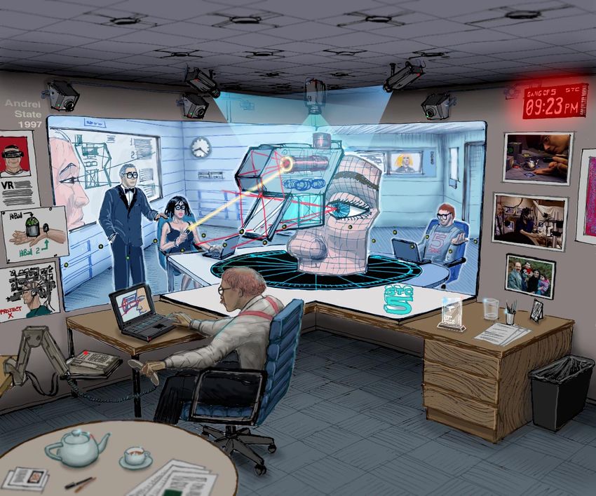
demonstrations of our dynamic modeling and display techniques. Figure 1: A conceptual sketch of the
office of the future. By replacing the
normal office lights with projectors,
† CB 3175, Sitterson Hall, Chapel Hill, NC, 27599-3175 one could obtain precise control
{raskar, welch, cutts, lake, stesin, fuchs}@cs.unc.edu over all of the light in the office. With the help of synchronized
http://www.cs.unc.edu/~{raskar, welch, cutts, lake, stesin, fuchs} cameras, the geometry and reflectance information can be captured
http://www.cs.brown.edu/stc/ for all of the visible surfaces in the office so that one can project
images on the surfaces, render images of the surfaces, or interpret
changes in the surfaces. The inset image is intended to help
differentiate between the projected images and the real objects in
the sketch.
1 INTRODUCTION
The impetus for this work is Henry Fuchs’s long-time desire to
build more compelling and useful systems for shared telepresence
and telecollaboration between distant individuals. It was Fuchs
who first inspired us with ideas for using a “sea of cameras” [39]
The Office of the Future: A Unified Approach to Image-Based Modeling and Spatially Immersive Displays 1
SIGGRAPH 98, Orlando, Florida, July 19-24, 1998                          COMPUTER GRAPHICS Proceedings, Annual Conference Series, 1998
and imperceptible lights to extract a 3D scene and to reconstruct it      to use the system, instead we would like something as convenient
at a remote location. These ideas have been refined over several          as the telephone—a SID built into an office.
years of collaboration with Ruzena Bajcsy of the University of                 While such an endeavor would probably not be cost-effective
Pennsylvania’s GRASP Laboratory [18], and with our colleagues             solely for the purpose of telecollaboration, if it were of high
in the NSF Science and Technology Center for Computer Graphics            enough quality one could use it for every-day 2D computer work,
and Scientific Visualization.                                             video, and 3D immersive visualization. However not only does the
      While we are making progress toward our vision for the office       construction of such SID’s require very careful engineering and
of the future, we do not yet have a complete working system—the           assembly, but certain characteristics vary with time and
ideas are by definition futuristic. As such, throughout the paper we      environmental factors such as temperature or vibration. Such time-
present a mix of demonstrated results from new methods, and               varying characteristics include the intrinsic and extrinsic projector
plausible ideas for future systems. We do our best to distinguish         parameters, intensity balance, color balance, edge alignment, and
between the two lest the reader be led to believe that we have            blending. These problems are most often addressed by periodic
implemented something that we have not.                                   mechanical projector calibration, however this approach becomes
      In the remainder of this section we present motivation for the      increasingly difficult and less reliable as the number of projectors
idea in the form of a story that outlines the developments that led       increases. Flight simulator developers have faced such problems
to the vision as presented in this paper. In section 2 we discuss the     for some time, and while they have developed digital calibration
principal components of the envisioned system, without                    systems, the systems tend to be highly specialized, thus increasing
necessarily discussing a specific implementation. In section 3 we         development cost and overall complexity. A more general-purpose
present our approach to actually implementing such an office of           autocalibration scheme would be preferable so that one could
the future. In section 4 we discuss our current implementation, and       modify the display surface or projector configuration as needed. If
in section 5 we discuss work to be done and future research topics.       one could modify the display surface, one could spontaneously add
Note that rather than including a specific “previous work” section        a “drawing board” onto their desktop and the system would
we have chosen to discuss related work throughout the paper.              account for it. If one had some flexibility over projector placement,
                                                                          one could for example add projectors in an overlapping manner to
Telecollaboration Interfaces                                              increase the display resolution (a high-resolution region), or image
While telecollaboration systems using 2D “talking heads” and              intensity, or side-by-side to increase the display surface area.
shared white boards have improved significantly over the years, we
believe that the through-the-window paradigm itself often inhibits        Telecollaboration Infrastructure and Applications
much of the interaction that would otherwise take place if the            There exists a relatively large body of work in telecollaboration
collaborators were actually together in the same room. In [5]             infrastructures and applications, not to mention a large body of
Buxton identifies several tasks for which commercial televideo            work in the area of Computer-Supported Cooperative Work
systems provide only limited support. Aside from limited                  (CSCW). Some representative examples are [34, 37, 6, 15, 28, 19,
resolution, part of the problem is that users are forced to maintain      27, 36, 3, 41, 10, 33, 37]. Our vision for the office of the future is
two separate egocenters (notions of where they are and who they           one in which all of this and similar work can be applied, we hope
are with): one in their local environment, and another egocenter          in new and exciting ways. We envision our office as a particularly
with the remote collaborators. The participants must then consider        compelling interface to be used in support of these efforts, and
and adjust normal behavior to “fit through the window.”                   every-day applications. We are aware of no other one system that
      One alternative is to implement a shared immersive virtual          attempts to achieve what we do in a similar unified approach.
environment where a user dons a head-mounted display (HMD),                    Of the existing telecollaboration efforts that we know about,
disappears from the real world, and enters a shared virtual               the only one that attempts to provide an office-like interface is
environment “inside the display” where for example they might             TelePort [20]. The TelePort system uses wall-sized displays that
see virtual objects along with 2D video avatars of their                  each show a synthetic scene that is blended with video images of
collaborators. Indeed, we have experimented with such paradigms,          remote participants. As participants move, their locations are
as have others. However this interface has several disadvantages.         tracked so that the images are rendered from the proper
Most obvious are the typical ergonomic problems, for example              perspective. The TelePort display is built into a room that is
size, weight, mobility, limited resolution, and limited field of view.    carefully designed to match the rendered room. The goal is for the
Furthermore, for immersive HMD’s, the resulting disassociation            virtual room to seem as an extension of the real room. They use
from a person’s comfortable surroundings can be disconcerting             carefully constructed geometric models for the office environment,
and can limit their ability to interact with other people and real        and video-based human avatars obtained by separating the remote
objects in the environment.                                               participants from the original background (via delta-keying).
      A more attractive alternative is to get the display off of the      Rather than building a specialized telecollaboration system that
user’s head, and to instead use a spatially immersive display (SID).      resembles an office, we want to build capability for a life-like
A SID is a display that physically surrounds the viewer with a            shared-room experience into existing offices.
panorama of imagery [4]. SID’s are typically room-sized, thus
accommodating multiple viewers, and are usually implemented               “Every Millimeter at Every Millisecond”
with multiple fixed front or rear-projection display units. Probably      One question in our minds was how should remote collaborators
the most well-known examples of general-purpose SID’s are the             and their environment appear remotely? While acceptable for some
Cave Automated Virtual Environment (CAVE™) [12], the related              tasks, we believe that 2D video-based avatars do not effectively
tiled-display PowerWall and Infinity Wall™ systems, and                   engender the sense of being with another person that is necessary
Alternate Realities’ VisionDome [2]. There are several good               for effective interpersonal communication. We want to see and
examples of telecollaboration applications where the users see and        interact with collaborators in 3D, as naturally as we do when we
interact with their remote collaborators using a CAVE™ or                 are in the same physical room: gesturing, pointing, walking,
CAVE™-like system, for example [34]. Such large systems                   waving, using all of the subtle nuances of both verbal and
typically require significant physical floor space, for example in a      nonverbal communication. A visually attractive possibility would
laboratory where there is room for both the screens and the               be to use a high-quality 3D image-based rendering or modeling
projection units. But we would like to avoid going “down the hall”        system for each participant (see for example [30, 38, 40, 43]).
                                                                          However we dream of a room-sized working volume, not only

The Office of the Future: A Unified Approach to Image-Based Modeling and Spatially Immersive Displays                                         2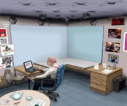
SIGGRAPH 98, Orlando, Florida, July 19-24, 1998                           COMPUTER GRAPHICS Proceedings, Annual Conference Series, 1998
because we want mobility, but also because we want to be able to           2.1 Dynamic Image-Based Modeling
see multiple participants, and to see everyone in their natural
surroundings, i.e. their offices. In short, we envision a system           One of the major components of the system is the module that will
similar to [20] where the local and remote offices appear to be            capture, continually and in real time, image-based models of the
physically joined together along some common junction such as a            office environment including all of the designated display surfaces.
designated wall that is actually a SID. But unlike [20] which              A large body of literature exists from computer vision regarding
overlays 2D video of the remote participants onto a virtual                the determination of depth from a scene. Some of the more
adjoining office, we want to see an image-based 3D reconstruction          common approaches include depth from motion, stereo, focus, and
of the remote office and all of its real contents including people         defocus. For our system we are interested not only in dynamic
and every-day clutter. That is, we have the ability to capture and         image-based modeling, but over a large volume also. With real-
remotely display a dynamic image-based model of an entire office.          time in mind, many of the techniques traditionally used are
      At some point when considering all of these factors, we came         difficult because of computational and bandwidth requirements. At
to the realization that if we had access to a dynamic image-based          CMU, a specialized hardware real-time depth from stereo
model of the entire office, including the designated SID surfaces,         architecture system has been developed [31]. It can take input from
we could automatically correct for changes in the time-varying             six cameras and produce, at 30 frames/second, a 256 × 240 depth
geometric characteristics of the SID. Furthermore, if several              map aligned with an intensity image. They also have the ability to
cameras could see the display surfaces from a variety of angles, we        produce an uncertainty estimation for each pixel. One advantage of
should be able to observe view-dependent intensity and color               this technique is the instantaneous sample-and-hold nature of
variations in the designated display surfaces, thus inferring the          depth from stereo. In contrast, using a laser scanner that cannot
surface reflectance properties. In other words, while obtaining an         complete a scan of the image in a single frame may result in
image-based model for the office we could autocalibrate all of the         distorted shapes as objects in the scene move. Any technique
designated display surfaces. Thus the realization that the SID could       which depends on computations made with several frames
in effect be almost anything or anywhere in the office! It wouldn’t        sampled at different times, including the structured light method
matter if the surfaces were irregularly shaped, or if the geometry         described in section 3.1, will have this problem.
was changing over time, the image-based model would indicate the                 Another real-time depth system has been developed by the
variations. And if one was willing to sacrifice some dynamic range         Columbia University Automated Visual Environment Group [38].
in the projected images, one might even be able to use the surface         They have demonstrated the ability to produce 512 × 480 depth
reflectance information to account for slight variations in view-          estimates at 30 Hz with an accuracy of 0.3%. Their technique
dependent intensity. Note that a crucial advantage of this unified         relies on a precise physical model of all the optical sensing and
approach is that because the autocalibration and the projection are        computational elements in the system: the optical transfer
done by the same device, one eliminates the problems of                    function, defocus, image sensing and sampling, and focus measure
calibration and drift of the calibration system itself.                    operators. They project a high frequency texture onto the scene
      Finally, we also note that if one has access to a dynamic            and, via the same optical path, image the scene. An advantage of
image-based model of the entire office, including the occupants,           this system over the depth from stereo is that they do not have to
one could potentially extract higher-level representations of the          worry about the correspondence problem faced by depth from
data, assign semantics to those higher-level objects, and then in          stereo. One concern is the distracting high frequency textures
real-time interpret and respond to object motion or collisions for         which much be projected onto the scene. These patterns could
the purpose of tracking, interaction, or augmented reality (AR).           prove unacceptable if the user wants to be in the environment
With such capability one could implement untethered interaction            while the scene is being captured.
as in the Luminous Room, where cameras and projectors serve as
“I/O Bulbs” [46, 47]. In this way for example one might be able to
                                                                           2.2 Rendering
track a person’s hands so that they could reach out and manipulate         Our vision for the office of the future requires the ability to
a floating 3D model, or perhaps one could detect collisions                generate images that when projected onto the display surfaces
between real and virtual objects so that virtual objects could be          appear correct to a moving head-tracked observer. This is true also
placed on the desk.                                                        for systems such as the CAVE™, but our situation is somewhat
      Figure 1 depicts a conceptual sketch of our office of the future,    unusual in that we want to be able to project onto general surfaces
replicated and in use at three different sites. Note the ceiling-          whereas the CAVE™ system is tailored to planar surfaces. Future
mounted projectors and cameras, the use of lightly-colored                 capabilities in image generation will allow the increased burden of
material on the designated SID wall and desk area, and the mixed           display on arbitrary surfaces to be realized.
use of that SID for simultaneous image-based and geometric                       An interesting technique is presented in [16] for the use of
model visualization.                                                       computer graphics systems in theater design, where she models the
      To achieve the above capabilities of acquisition, calibration,       appearance of backdrops from the audience’s perspective. If left
and display in a continuously changing office scene with both local        uncorrected, the backdrops would appear distorted. Essentially, we
and remote participants, we dream of being able to control light in        are faced with the same problem in our system, except with
the office over “every millimeter at every millisecond.”                   multiple projectors. We need to determine how to predistort the
                                                                           images such that, when projected from the projector’s viewpoint, it
2 FUNDAMENTAL COMPONENTS                                                   will look correct from the user’s viewpoint. Dorsey et al. also
Our idea for the office of the future brings together several              extend this technique to model the projector optics and
fundamental areas of computer science, components that can be              demonstrates an extended radiosity method to simulate directional
enumerated independently from descriptions of their actual                 lighting characteristics.
implementations. While one goal of this paper is to present the
specific implementation of such a system, this does not preclude
                                                                           2.3 Spatially Immersive Displays
the use of any of the techniques others have developed in each of          The most well known spatially immersive display in the graphics
these areas. Quite to the contrary, we believe there are trade-offs        community is probably the CAVE™ [12]. The CAVE™ exists in
with all of these techniques which warrant further investigation.          many forms, typically it is configured as a left, right, and rear wall
                                                                           rear projection system. In some implementations they use a mirror
                                                                           above the CAVE™ that projects an image onto the floor. While the

The Office of the Future: A Unified Approach to Image-Based Modeling and Spatially Immersive Displays                                          3
SIGGRAPH 98, Orlando, Florida, July 19-24, 1998 COMPUTER GRAPHICS Proceedings, Annual Conference Series, 1998
CAVE™ does provide head-tracked stereo views surrounding the
user of the system, current implementations are limited to 1
projector displayed on each wall. The CAVE™ does not deal with
intensity blending and has no method of capturing the geometry of
the environment, which is reasonable since this was not an a
intended goal of their system.
The military simulation/flight simulator industry is full of
numerous examples of spatially immersive displays [9, 23, 29, 32,
35]. These systems typical use CRT projectors which need
frequent calibration. Also, they usually (but not always) restrict
themselves to matching the seams of the display instead of
considering the whole display area as something that needs to be
blended seamlessly. Another technique of the flight simulator
industry is to place a high resolution display in the center of view
of the user and project a low resolution image on the surrounding
screen, or to only project an image in the view frustum of the user.
While this is effective, it cannot easily be repositioned and may
show a seam where the high resolution image meets the low
resolution image. The seam is a problem because it is
disconcerting and severely disrupts the goal of achieving a feeling
of being somewhere else—the user is always reminded they are b
looking at an imperfect display surface. The attempts at creating a
seamless display are discussed in the previously cited flight Figure 2: Our current implementation of the office of the future.
simulator papers. (a) The cameras and digital light projectors are mounted near the
Domed displays are another example [2]. Such systems are ceiling using Unistrut material. (b) The walls consist of white
often limited to only one high resolution projector and have rarely foam-core board mounted on vertical posts. As shown in (b),
employed a mechanism to capture depth or projection surface they are used as display surfaces for a spatially-immersive
information from the scene. A method is presented in [29] that display (SID).
corrects the warping of the dome by modeling a dome with a 5-
degree polygon mesh and a GUI for manipulating the coordinates typically need high accuracy so that the projections are correct. To
of this mesh, but this is not done in real-time or automatically: model dynamically changing scenes we need higher update rates
direct user intervention is required. This method is meant to only to represent motion with potentially decreased resolution or
be used when the system is moved or for some infrequent reason accuracy. The method should be non-intrusive so that people can
falls out of alignment, it is not meant to be a method that can work in the environment. This prevents the use of lasers or other
update the projection in real-time as the display surface changes invasive methods.
shape or occlusion properties. Our system currently uses one video camera and one
A final important point about all of these systems is that they projector in a pair, although multiple cameras could work with one
rely on special geometric configurations and they present no projector [43]. The correspondence problem is solved by
general solution, which is a completely reasonable design decision projecting binary coded vertical bars [14]. The camera looks at a
on their part: typically they had an unchanging environment with set of n successive images, creates binary images using adaptive
uniform, ideal display surfaces. Also, they had control of every thresholding on a per-pixel basis, and generates an n-bit code for
issue of the display system, from the lighting to the precise every pixel corresponding to the code for the vertical bar that was
n
calibration of the projectors. Instead, we propose a general solution imaged at this pixel. This allows us to distinguish between 2
to the problem of projecting onto arbitrary display surfaces with projected vertical bars. A pre-computed sparse triangulation
real-time, automatic calibration procedures. Understand that we do lookup table based on calibration data allows trilinear interpolation
not necessarily believe people will want to project on every type of to compute intersection of pseudo-camera rays and projected
surface or object, but we feel that thinking about the problem in vertical planes. The 3D coordinates of the surface points imaged at
this way is useful. every pixel are later used with color information to complete the
image-based model. The vertical bars can be projected repeatedly
3 METHODS to compute depth for dynamic scenes. The same method can be
used for scanning walls, people or moving objects with different
In this section we describe the idea of using cameras and
levels of sophistication for sub-pixel image thresholding. See
projectors that can be operated in either a capture or display mode.
Figure 3 for some still-frame sample results.
(See Figure 2 and Figure 8.) When in capture mode, the projectors
A choice of a camera and projector to actively scan 3D
and cameras can be used together to obtain per-pixel depth and
environments is necessitated by the fact that display surfaces may
reflectance information from the designated display surfaces.
lack texture to provide enough correspondence cues. Use of the
When in display mode, the image-based models may be used to
same projector for scanning and display allows unification of the
render and then project geometrically and photometrically correct
two tasks and the only additional component is a camera. Speed
images onto the (potentially irregular) display surfaces.
versus accuracy trade-offs led us to two types of camera-projector
3.1 Dynamic Image-Based Modeling pairs. Relatively static display surfaces such as walls and furniture
in office scenes are modeled more accurately and slowly by the
Image-based modeling is a difficult problem, one that has occupied outward looking pairs of camera-projector than people and moving
the computer vision community for many years. objects, which are scanned by inward looking pairs of camera-
projectors.
Depth Extraction
The difficult part of using two separate devices for depth
The depth extraction method for office scenes should work in large extraction is calibration. We use [45] first to find intrinsic and
working volumes populated with areas with high frequency texture extrinsic parameters of the camera using a checkerboard pattern on
as well as surfaces that lack texture. To model display surfaces, we
The Office of the Future: A Unified Approach to Image-Based Modeling and Spatially Immersive Displays 4SIGGRAPH 98, Orlando, Florida, July 19-24, 1998 COMPUTER GRAPHICS Proceedings, Annual Conference Series, 1998
p9 p1 p1 p2 p2 p9
time
Sequence of patterns and their complements.
original complement
light pattern
flat field
Figure 3: Some example results (still frames from live updates) Figure 4: Pattern and complement are visually integrated over
of depth extraction using binary coded structured light. time, the result is the appearance of a flat field, or “white” light.
a flat surface. Then the same method is used to calibrate the display on the depth extracted surface. This eliminating problems
projector with respect to the same flat surface. Combining the two due to drift or misalignment.
gives the relationship between the camera and the projector. To
find the relationship between two camera-projector pairs, the 3.2 Imperceptible Structured Light
transformation between the two cameras is first determined by With respect to the structured light described in section 3.1, our
viewing a common checkerboard pattern on a flat surface. Then, goal is to make it appear to the casual observer as nothing more
using the method described above, the two pairs are calibrated with than incandescent white light, not a succession of flashing binary
respect to the working volume. The procedure is easier if the patterns. Our method for doing this is to use imperceptible
frustums of the two cameras overlap considerably. structured light. The approach is a combination of time-division
Detection of changes in scene geometry by camera image multiplexing and light cancellation techniques to hide the patterns
differencing is not robust when display surfaces lack texture. in a rapid series of white-light projections. Figure 4 depicts a
However, changes in a projected random texture can be imaged sequence of patterns projected in time. A binary structured light
The random texture itself will be imperceptible to the human eye approach such as ours uses n patterns to resolve 2 n projected
as described in section 3.2. Detected changes in scene geometry vertical bars. The period of pattern repetition would be, for
over a period of time could be the result of either actual changes in example, 1/60 second for a 60 Hz depth extraction rate. Figure 4
the surfaces or drift in the calibrated system. depicts how a given pattern p i and complement p i are integrated
The use of cameras allow the possibility to self-calibrate the by the visual system in such a way that the sequence appears to be
system periodically to compensate for errors due to environmental the projection of a flat field or white light. The same approach can
factors such as temperature or vibrations in the setup. be applied to project imperceptible structured light along with
Color and Reflectance video or graphics images, facilitating imperceptible
autocalibration of designated display surfaces. We use a digital
The projector is used in two modes, scene extraction and display.
light projector [25, 26] which uses PCM to project the pattern and
To get color information about the surfaces the projector is used as
its complement. A synchronized camera can measure the
a bright light source along with a synchronized camera. However,
structured light by integrating light during the pattern projection.
the modes can be interleaved by inserting completely white frames
While limited access to digital light projector specifications
in between the display frames. In the binary pulse-coded
currently limits our ability to implement completely imperceptible
modulation (PCM) coded light projectors, only a few bits are used
image-based modeling, we are able to separately demonstrate real-
to project white frames while other bits can be used to project the
time capture and imperceptible structured light. Figure 5 shows the
display frames at reduced color resolution.
effect in a laboratory experiment. Figure 6 shows the use of a
Currently we illuminate the scene with a black followed by
similar approach to embed imperceptible structured light in a still
white pattern and observe the resultant dark image and bright
image as opposed to white light. We are working together with the
image from one view point to estimate the per-pixel reflectance
developers of the projector technology to obtain lower-level access
function. The reflectance function is primarily used to threshold
to the technology, which will introduce a whole new realm of
images of projected binary coded structured light patterns
possibilities for dynamic structured light and display.
assuming the camera response is linear to intensity. Camera
response curves can be estimated by illuminating the scene with 3.3 Geometric Registration
different levels of intensity. To complete the image based model,
surfaces in the scene can be sampled from multiple view points to The depth data acquired from different cameras needs to be zipped
estimate a bidirectional reflectance distribution (BRDF) function. together to complete the display surface geometry. This is required
The camera is used for per-pixel depth extraction as well as for generating correct images from a single projector for
color extraction. Since the two procedures share the same optical multisurfaces [42] and also for intensity blending if the projections
axis, there is no drift. Similarly, the same projector is used for from multiple projectors overlap. The depth images are taken from
projecting structured light patterns, for depth extraction, and for distinct cameras and are in different coordinate systems. Thus in
order to tile the extracted surfaces together corresponding points
The Office of the Future: A Unified Approach to Image-Based Modeling and Spatially Immersive Displays 5SIGGRAPH 98, Orlando, Florida, July 19-24, 1998 COMPUTER GRAPHICS Proceedings, Annual Conference Series, 1998
3.4 Rendering and Display
Our goal is to generate images that appear correct to an observer
when projected onto (potentially irregular) display surfaces. Since
the observer can move around in the office, we currently use
magnetic head-tracking to determine the viewer’s location. The
inputs to the algorithm are a model of the surface, the projector’s
intrinsic and extrinsic parameters, the viewer’s location, and a
camera “desired image,” the image which we want the viewer to see. The
desired image will typically be the result of conventional 3-D
rendering.
Our algorithm can work with any general type of surface
representation (e.g. NURBs), as long as the model of the real-
projector world display surface is accurate. Likewise, rendering could be
done with many different methods (e.g. ray-tracing); our current
implementation uses projective textures with OpenGL primitives
to achieve hardware acceleration. The underlying projective
Figure 5: Imperceptible structured light is textures [44] technique is an extension of perspectively-correct
demonstrated in the laboratory. The digital texture mapping that can be used to do arbitrary projection of two
projector on the left is projecting the text dimensional images onto geometry in real-time.
shown in the monitor and its complement , We describe a two pass approach for rendering and displaying
however the text can only be seen with a synchronized camera
such as that sitting on the projector above. The inset snapshot of images of 3D scenes on potentially irregular surfaces. In the first
an oscilloscope shows the pulses that correspond to the brief pass, we compute the “desired image” for the viewer by rendering
time when the pattern (text in this case) is being projected. the 3D scene from the observer’s viewpoint. This desired image is
stored as a texture map. In the second pass the texture is effectively
projected from the user’s viewpoint onto the polygonal model of
If you can read this, the display surface. The display surface (with the desired image
then you are seeing texture mapped onto it) is then rendered from the projector’s
Imperceptible viewpoint. The resulting image, when displayed by the projector,
Structured will produce the desired image for the viewer. As the user moves,
a b Light cab the desired image changes and it is also projected from the user’s
new location.
Multiple projectors can be used to increase the display surface
area. To ensure complete coverage of the display surface, every
part of the display surface must be visible to at least one projector.
To ensure complete coverage from a given viewpoint, at least one
projector must be able to image on every surface visible from that
viewpoint. The projectors’ viewpoints in the second pass typically
remains fixed. Neither projector overlap nor self-occlusions of
display surfaces from observer’s viewpoint need hinder the
effective image from the user’s viewpoint. See Figure 7.
To specify the viewing direction for projecting textures with
monocular viewing, we only need the position of the user and not
orientation. A field of view that contains all the polygons of the
synthetic object is sufficient for the frustum of texture projection.
This frustum may be trimmed if it exceeds the frustum of the
d display surface model.The frustum is oriented from the viewer’s
Figure 6: Imperceptible structured light embedded in images. (a) location toward the polygonal model of display surfaces. The
An initial image (Tokaj, Hungary). (b) The binary image that is user’s frustum parameters during the first pass and texture
to be imperceptible. (c) The two images combined and mapped projection in the second pass are identical.
to the proper time-division bit sequence. (d) The final result, We assume that the projectors have no radial distortion and
showing the initial image (with reduced dynamic range) being hence the projectors can be modeled with a pinhole camera. For
projected on the wall, while the embedded imperceptible image the optics of digital micromirror device (DMD) projectors, this
is captured and displayed on the monitor (lower left). assumption is valid. However, if the projector has radial distortion,
we must pre-distort the rendered image before it is sent to the
from overlap regions are used. The corresponding points are projector framebuffer. This pre-distortion can be done using non-
generated using the binary coded structured light approach for linear 3D warp of display surface geometry or using screen space
rows and columns of projector pixels. The binary code of an 2D warp with texture mapping.
imaged point uniquely identifies the corresponding projector pixel.
Pairs of pixels in two cameras that share the binary code are used Challenges
to compute transformation between depth data sets. Note that this Speed.
transformation between two cameras can also be pre-computed The two pass rendering method consists of normal 3D rendering in
during calibration stage but is usually not sufficiently accurate to the first pass, followed by a second pass that maps the desired
register two depth data sets. Otherwise, for blending purposes, the image to a display surface model. The additional cost of the
geometric correspondence between pixels of two different algorithm comes from transferring the framebuffer from the first
projectors is established by observing the projection overlap region pass into texture memory and rendering the display surface model
from a single camera. We assume that every pair of images has a with texture mapping applied in the second pass. Thus it is crucial
substantial overlap (about one-third of its total area). to simplify the display surface geometries.
The Office of the Future: A Unified Approach to Image-Based Modeling and Spatially Immersive Displays 6SIGGRAPH 98, Orlando, Florida, July 19-24, 1998 COMPUTER GRAPHICS Proceedings, Annual Conference Series, 1998
the transitions between the projected images: one can either design
the system such that the images do not overlap but can be adjusted
so that they are barely touching and thus “seamless,” or one can
allow projected images to overlap and employ some means of
blending. The second approach typically uses a roll-off function
a b such as a linear ramp or a cosine curve to smooth the transition
between projectors.
Designers of the CAVE™ exercise the first option by limiting
the system to a well-defined, relatively simple screen arrangement
whereby no projectors overlap. However we want to be able to
project images onto arbitrary potentially irregular display surfaces
in the office, which means that we cannot use the first approach as
we assume no control over the surfaces. Furthermore, we envision
a more flexible setup whereby multiple projectors can be used to
project into the same space in order to achieve higher resolution
(e.g., via a “high-resolution insert”) or increased light.
We implemented a weighting function by assigning alpha
values between 0 and 1 to every pixel in every projector, and as
described in section 3.3 ensure that every illuminated world point
corresponding to a single camera pixel has an alpha sum equal to
one. This assumes that the projectors have similar intensity
response. There are two cases: a point resulting from a projection
of only one projector and a point resulting from a number of
c projectors. In the first case the solution is trivial. However, in the
second case, the case where overlap occurs, we make alpha values
Figure 7: Multisurface rendering. (a) A teapot projected onto a a function of the distance to the beginning/end of overlapping
single planar surface. (b) A distorted projection resulting from region, with the constraint that alpha values of points from
the introduction of a second planar display surface. (c) The final
corrected projection obtained by extracting the display surface different projectors, corresponding to the same point in space,
geometry and then employing our two-pass rendering scheme. must sum up to one. To assign different weights to projector pixels,
The edges of the second planar surface—shown leaning against we actually create an alpha image for each projector. This image
the wall on the desk in (c)—are highlighted with a dashed line. contains (1 - desired_alpha) at each pixel. This alpha image is
rendered last. In our OpenGL implementation this is achieved
Parallelization using transparent textures. A camera in the closed loop system
If more than one projector is used, each projector can have a allows one to photometrically correct images even when the
separate display engine. Rendering can be done in parallel, and projectors have different brightness or when the display surface
each display engine need only load those parts of the display has non-uniform reflectance properties. Although the digital light
surface model that are visible from the corresponding projector. projectors have linear intensity response, they use a de-gamma
We have some initial evidence [42] that our method is faster versus correction [25]. Use of alpha image allows us to compensate the
conventional rendering techniques with multiple projectors, de-gamma correction.
complex displays, or complex graphics models. The reason is that
the first pass of the algorithm (conventional rendering) only needs
3.6 Simplification of Depth Data
to be done once, and then the second pass can be performed for Dynamic image-based modeling of an entire office will result in
each projector. Conventional techniques require the graphics tremendously large data sets, given that the data would be per-pixel
model to be re-rendered for each projector or even for each for multiple cameras, occurring at video rates. However it is
polygon in the display surface. reasonable to expect that the majority of the data is highly
If the first pass is also parallelized, all the corresponding correlated both temporally and spatially. In fact most of the office
graphics pipelines need to access the synthetic model being is unlikely to change dramatically over short periods of time, in
displayed simultaneously. This could be a problem if the model is particular this is likely to be true for the office walls and most
dynamically changing and the graphics pipeline must read the designated display surfaces. It makes sense to attempt to simplify
model during every display iteration. Other parallelization issues the data so that the system does not have to deal with such a
include if the display surface model is dynamic, as well as network horrendous volume of data. For example, Radim Sara and Ruzena
issues if the display engines are on different machines. Bajcsy at the University of Pennsylvania have created a depth data
Latency set of an office that has approximately half a million vertices. The
simplification method must be careful not to simplify in regions of
There is inherent latency in the system in addition to traditional
rapid change or high curvature where information might be lost.
tracking and rendering latency due to two pass method for drawing
The automatic reconstruction of surfaces from range data is
models. For large models, rendering times could be different for
explored in [13, 1, 8, 11, 17, 22].
different projectors so that there is inter-projector delay during
Unfortunately, the dynamic nature and the presence of noise
rendering. If all the projectors are driven from a single machine,
in our system, disallow the use of well-established simplification
then setting up viewports within a single rendering program for
algorithms. The method we currently employ is not a well-defined
each projector and synchronously updating the framebuffers will
mathematical approach, but rather a heuristic-based method that
eliminate this problem.
produced qualitatively pleasing results based on the characteristics
3.5 Generating Blending Functions of our data sets. We first apply a curvature approach to the data set
using a tangent method similar to [24], and we then use a
We use the traditional computer graphics phrase “alpha values” to Euclidean distance approach on the remaining points. We chose
describe the blending functions. When building some sort of a tiled this particular sequence of steps because the curvature method is
multi-projector SID, one is faced with two approaches for handling usually much more successful in eliminating points than the
The Office of the Future: A Unified Approach to Image-Based Modeling and Spatially Immersive Displays 7SIGGRAPH 98, Orlando, Florida, July 19-24, 1998 COMPUTER GRAPHICS Proceedings, Annual Conference Series, 1998
second one. This approach produces elimination rates of 80% to 640 × 480 resolution video cameras (Figure 2). The outward
90% without any visible loss of information. This is because most looking five projectors are driven simultaneously from an SGI
of the objects in the office environment are locally planar. Infinite Reality. Four of these project on relatively vertical surfaces
and one projects down on the table and the floor. The binary PCM
3.7 Tracking coded light projectors project 24 bit color at a 60Hz update rate.
While our office of the future could certainly and possibly very The projectors allow off-axis projection with a small offset without
effectively be used in a 2D-only mode, we believe that it is more significant focus problems. The camera framegrabbers are SGI
compelling to consider its additional use as a 3D visualization O2s and currently we use a video switcher to switch between the
environment. We need the ability to track viewers’ heads in order video cameras while capturing images of the environment. We
to render perspectively correct images. Interestingly enough, for expect that in the very near future the rendering will be done in
monoscopic viewing one does not need the orientation of the eye different viewports of a single window and hence can be used to
because the display image is uniquely determined by the eye maintain synchronous updates of all projector framebuffers. The
position. For stereoscopic viewing one needs to be able to either system also includes an Ascension magnetic tracker for tracking
track one eye and the user’s head orientation, or two eyes, each user position.
with position only. The system involves projecting synthetic The walls of the office are made up of relatively inexpensive
foam-core board, and does not need solid support because the
system supports non-planar surfaces and off-axis projection. A
era
r
cam
separate projector-camera pair setup is used to create dynamic
cto
pr
cam
image based model in a small working volume of 3 × 3 × 2 feet,
oj
oje
era
ceiling
ec
pr
to
and can be used for dynamic image-based modeling of human
r
faces (see Figure 3) [43]. The system creates a 640 × 240 depth
map at three updates per second, which is texture mapped with live
video. Using a direct digital interface to the digital light projectors
from a PC, we have been able to project patterns that are
wall
imperceptible to human eye but visible from a synchronized
camera (see Figure 5). We have capability to change the binary
PCM coding of light for the projectors allowing us to use different
bits for different purposes; in particular we have the ability to burn
an equal-bit-time PROM for the projectors which allows us to
demonstrate compelling imperceptible structured light (see
Figure 5). With the equal-bit-time PROM, a binary pattern can be
displayed 24 times per 60 Hz frame, i.e. every 694 microseconds.
Thus a pattern and its complement can be displayed sequentially in
display approximately 1.4 milliseconds. The synchronized camera with
surfaces exposure time less than 700 microsecond was used in Figure 5.
Using this PROM we could in theory project and capture
60 × 24 = 1440 binary patterns per second. Our current
framegrabbers, however, can process only 60 images per second. A
better digital interface to DLP’s will also allow us to render stereo
images at 60 Hz.
Figure 8: Digital projectors and cameras work together to
capture depth, color, and surface reflectance information for Although we expect the participants to be seating in a chair
objects and participants in the scene. A subset of the projectors most of the time (Figure 2), the current setup allows participants of
is also used for display purposes; captured display surface depth, average height (under 6 feet) to stand and move around without
color, and reflectance information can be used to autocalibrate blocking the projection on the walls if they are at least 4 feet away
the display surfaces so that projected images are geometrically from the walls.
and photometrically correct from the viewer’s viewpoint, and so The office of the future setup allows scalability in terms of
overlapping projections are properly blended more pairs of camera and projector to either increase resolution of
extracted surfaces, or resolution of display on surfaces. The system
images onto real surfaces for which the extracted surface model is other than computer hardware costs approximately $35,000. We
assumed to be correct in world space. Any small error in tracker expect minimal maintenance of projector, cameras or display
reading (after transformation) in world space will result in visibly surfaces because the system employs self-calibration methods.
incorrect registration between projected images and the display
surfaces. This situation is similar to augmented reality systems 5 FUTURE WORK
where traditionally a vision based registration system is used to Much work remains to be done, some of which we have concrete
correct the tracker readings. A similar closed loop system may be plans to attack, some we are attacking with collaborations, and
necessary for accurate rendering for our system. some we hope others will pursue.
We plan to integrate scene acquisition and display in such a
4 CURRENT IMPLEMENTATION way that the acquisition is imperceptible, or at least unobtrusive.
While a complete realization of such an office of the future is, by This will involve some combination of light control and cameras,
definition, years away, we are making steady progress and present possibly wide-field-of-view high-resolution clusters as described
here some promising results and demonstrations. We have in [7]. Together with our collaborators in the GRASP Laboratory at
implemented a working system using projective textures. We have the University of Pennsylvania, we are exploring the continuum of
also independently demonstrated 1) a depth extraction system options between strict control of all of the lights in the
running at 3 Hz, 2) imperceptible structured light, and 3) initial environment (as outlined herein) and little or no control of the
experiments in intensity blending. lights but using multiple cameras and passive correlation-based
The office size is 10 × 10 × 10 feet, and is populated with techniques. We expect to have within the coming year a new
five 800 × 600 resolution digital light projectors and two
The Office of the Future: A Unified Approach to Image-Based Modeling and Spatially Immersive Displays 8SIGGRAPH 98, Orlando, Florida, July 19-24, 1998 COMPUTER GRAPHICS Proceedings, Annual Conference Series, 1998
multibaseline correlation system on hand for experiments with our We thank Nick England for sharing his significant knowledge
structured light acquisition and display environment. about wide-area tiled display systems, both in terms of past work
As part of scene acquisition, one can detect display surface and fundamental issues; Mary Whitton, David Harrison, John
changes and adapt the rendering accordingly. Currently it can be Thomas, Kurtis Keller, and Jim Mahaney for their help in
done at non-interactive rates. Eventually we also want to explore designing, arranging, and constructing the prototype office of the
methods as in [21] to detect surface changes for purposes such as future; Todd Gaul for help with our video taping; Jean-Yves
tracking and gestural input. Bouguet of Caltech for the camera calibration code and useful
We also want to improve image generation with better discussions; Nick Vallidis for his work on creating new DLP
blending, by exploiting image-based rendering methods to binary PCM coding; Andy Ade and Jai Glasgow for their
construct a target image from multiple reference images. There is a administrative help; our department’s Computer Services staff
good possibility that a distributed rendering scheme employing the members for keeping our networks and machines humming in
multiprojector and multisurface display algorithms that we present spite of our experimental modifications; and Hans Weber and Rui
and analyze in [42] will prove to be effective. In addition, we want Bastos for help photographing the imperceptible structured light
to correct for surface reflectance discontinuities dynamically, and demonstrations. Finally, we gratefully acknowledge Andrei State
to make use of the information during run-time to adjust the for his illustrations of the office of the future (Figure 1).
rendered images.
We are planning to use our system in an on-going References
telecollaboration involving multi-disciplinary mechanical design
[1] Bajaj, C.L., F. Bernardini, and G. Xu. “Automatic
and manufacturing with our collaborators in the NSF Science and reconstruction of surfaces and scalar fields from 3D scans,”
Technology Center for Graphics and Visualization. In addition as SIGGRAPH 95 Conference Proceedings, Annual Conference
part of The Tele-Immersion Initiative we are planning to make use Series, ACM SIGGRAPH, Addison-Wesley, pp. 109-118,
of the CAVE™ library or similar framework to connect several August 1995.
laboratories over high speed networks with novel immersive [2] Bennett, David T. Chairman and Co-Founder of Alternate
display environments. Realities Corporation. Internet: http://www.virtual-reality.com. 215
Southport Drive Suite 1300 Morrisville, NC 27560.
6 SUMMARY AND CONCLUSIONS [3] Bowen, Loftin, R. “Hands Across the Atlantic,” IEEE Computer
We have shown initial results for a novel semi-immersive display Graphics and Applications, Vol. 17, No. 2, pp. 78-79, March-April
in an office-like environment, one that combines acquisition and 1997.
display. We have developed techniques to acquire the geometry of [4] Bryson, Steve, David Zeltzer, Mark T. Bolas, Bertrand de La
an irregular surface and then modify rendering to allow projection Chapelle, and David Bennett. “The Future of Virtual Reality: Head
Mounted Displays Versus Spatially Immersive Displays,”
onto that irregular surface so that it looks correct to an observer at SIGGRAPH 97 Conference Proceedings, Annual Conference
a known location. We have described a method of injecting Series, ACM SIGGRAPH, Addison-Wesley, pp. 485-486, August
structured light into a scene that is imperceptible to the participants 1997.
but measurable to synchronized cameras. These techniques can be [5] Buxton, W., Sellen, A. & Sheasby, M. “Interfaces for multiparty
applied to other display environments which use multiple videoconferencing,” In K. Finn, A. Sellen & S. Wilber (Eds.). Video
projectors or that involve complex display geometries. Mediated Communication. Hillsdale, N.J.: Erlbaum, pp. 385-400,
In conclusion, we note that a major trend in computer science 1997.
over the past few decades has been from one to many, from being [6] Capin, Tolga K., Hansrudi Noser, Daniel Thalmann, Igor
restricted by resources' proximity to employing resources Sunday Pandzic and Nadia Magnenat Thalman. “Virtual Human
irrespective of their locations. One field unaffected by this global Representation and Communication in VLNet,” IEEE Computer
development has been the computer display or the area where the Graphics and Applications, Vol. 17, No. 2, pp. 42-53, March-April
results of our work are being presented. Our system pushes this 1997.
envelope, thus enabling any object, or a collection of such, located [7] Chi, Vern, Matt Cutts, Henry Fuchs, Kurtis Keller, Greg Welch,
anywhere to be used as a display surface. From now on, one does Mark Bloomenthal, Elaine Cohen, Sam Drake, Russ Fish, Rich
not have to cramp the information into a relatively small monitor, Riesenfeld. 1998. “A Wide Field-of-View Camera Cluster”,
University of North Carolina at Chapel Hill, Dept of Computer
but to have as much space as possible and to be limited only by the Science, Technical Report TR98-018.
amount of space around. Anything can be a display surface - a wall
[8] Chien, C.H., Y.B. Sim, and J.K. Aggarwal. “Generation of
or a table, and anywhere - be it an office or a conference hall. Of volume/surface octree from range data,” In The Computer Graphics
course, the system faces many challenges, but they can be Society Conference on Computer Vision and Pattern Recognition,
overcome by the increasing power of graphics hardware and pp. 254-260, June 1988.
general purpose computing. [9] Clodfelter, Robert M. “Predicting Display System
Performance,” Presented at the 1996 IMAGE Conference,
7 ACKNOWLEDGMENTS Scottsdale, AZ, pp. 1-5, June 23-28, 1996.
This work was supported by (1) the National Science Foundation [10] Conner, D.B, Cutts, M., Fish, R., Fuchs, H., Holden, L.,
Cooperative Agreement no. ASC-8920219: “Science and Jacobs, M., Loss, B., Markosian, L., Riesenfeld, R., and Turk, G.
Technology Center for Computer Graphics and Scientific “An Immersive Tool for Wide-Area Collaborative Design,”
Visualization”, Center Director Andy van Dam (Brown TeamCAD, the First Graphics Visualization, and Usability (GVU)
Workshop on Collaborative Design. Atlanta, Georgia, May 12-13,
University). Principal Investigators Andy van Dam, Al Barr 1997.
(California Institute of Technology), Don Greenberg (Cornell
[11] Connolly, C.I. “Cumulative generation of octree models from
University), Henry Fuchs (University of North Carolina at Chapel range data,” Proceedings, Int’l. Conference Robotics, pp. 25-32,
Hill), Rich Riesenfeld (University of Utah); (2) the “National Tele- March 1984.
Immersion Initiative” which is sponsored by Advanced Networks [12] Cruz-Neira, Carolina, Daniel J. Sandin, and Thomas A.
and Services, President and Chief Executive Officer Al Weis, Chief DeFanti. “Surround-Screen Projection-Based Virtual Reality: The
Scientist Jaron Lanier; and (3) DARPA grant no. N66001-97-1- Design and Implementation of the CAVE,” Computer Graphics,
8919: “Three Applications of Digital Light Projection for Tiled SIGGRAPH Annual Conference Proceedings, 1993.
Display and 3-D Scene Capture.”
The Office of the Future: A Unified Approach to Image-Based Modeling and Spatially Immersive Displays 9You can also read