UCC S5 REVO-2 CMM controller installation guide - UCC S5 REVO-2 CMM controller installation guide
←
→
Page content transcription
If your browser does not render page correctly, please read the page content below
UCC S5 REVO-2 CMM controller installation guide

www.renishaw.com

UCC S5 REVO-2 CMM controller installation
guide
Documentation part number: H-1000-7598-04-A

Issued 07 2021                                    1

UCC S5 REVO-2 CMM controller installation guide

www.renishaw.com

General information
© 2015 ‐ 2021 Renishaw plc. All rights reserved.

This document may not be copied or reproduced in whole or in part, or transferred to any other media or language by any means, without the
prior written permission of Renishaw.

Disclaimer
WHILE CONSIDERABLE EFFORT WAS MADE TO VERIFY THE ACCURACY OF THIS DOCUMENT AT PUBLICATION, ALL WARRANTIES,
CONDITIONS, REPRESENTATIONS AND LIABILITY, HOWSOEVER ARISING, ARE EXCLUDED TO THE EXTENT PERMITTED BY LAW.

RENISHAW RESERVES THE RIGHT TO MAKE CHANGES TO THIS DOCUMENT AND TO THE EQUIPMENT, AND/OR SOFTWARE AND THE
SPECIFICATION DESCRIBED HEREIN WITHOUT OBLIGATION TO PROVIDE NOTICE OF SUCH CHANGES.

Trade marks
RENISHAW®, the probe symbol and REVO® are registered trade marks of Renishaw plc.

Renishaw product names, designations and the mark ‘apply innovation' are trade marks of Renishaw plc or its subsidiaries.

Other brand, product or company names are trade marks of their respective owners.

WEEE

The use of this symbol on Renishaw products and / or accompanying documentation indicates that the product should not be mixed with
general household waste upon disposal. It is the responsibility of the end user to dispose of this product at a designated collection point for
waste electrical and electronic equipment (WEEE) to enable reuse or recycling. Correct disposal of this product will help to save valuable
resources and prevent potential negative effects on the environment. For more information, please contact your local waste disposal service
or Renishaw distributor.

Warranty
Unless you and Renishaw have agreed and signed a separate written agreement, the equipment and/or software are sold subject to the
Renishaw Standard Terms and Conditions supplied with such equipment and/or software, or available on request from your local Renishaw
office.

Renishaw warrants its equipment and software for a limited period (as set out in the Standard Terms and Conditions), provided that they are
installed and used exactly as defined in associated Renishaw documentation. You should consult these Standard Terms and Conditions to find
out the full details of your warranty.

Equipment and/or software purchased by you from a third-party supplier is subject to separate terms and conditions supplied with such
equipment and/or software. You should contact your third-party supplier for details.

Issued 07 2021                                                                                                                            2
UCC S5 REVO-2 CMM controller installation guide

www.renishaw.com

Care of equipment
Renishaw probes and associated systems are precision tools used for obtaining precise measurements and must therefore be treated with
care.

Changes to Renishaw products
Renishaw reserves the right to improve, change or modify its hardware or software without incurring any obligations to make changes to
Renishaw equipment previously sold.

Company registration details
Renishaw plc. Registered in England and Wales. Company no: 1106260. Registered office: New Mills, Wotton-under-Edge, Gloucestershire,
GL12 8JR, UK.

Packaging
To aid end user recycling and disposal the materials used in the different components of the packaging are stated here:

 Packaging component                Material                            94/62/EC code                      94/62/EC number

 Outer box                          Cardboard - 70% recycled            PAP                                20
                                    content
 Packing foam                       Polyurethane                        PU                                 7
 Packing foam                       Cross-linked polyethylene           LDPE                               4
 Plastic bags                       Low density polyethylene bag        LDPE                               4

Issued 07 2021                                                                                                                    3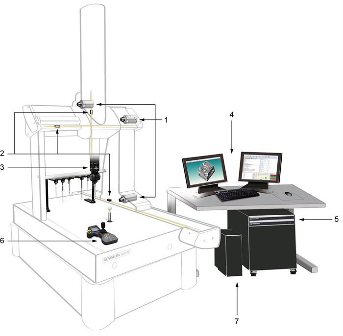
UCC S5 REVO-2 CMM controller installation guide

www.renishaw.com

Product compliance
EU declaration of conformity
Contact Renishaw plc or visit www.renishaw.com/EUCMM for the full EU declaration.

UK declaration of conformity
Contact Renishaw plc or visit www.renishaw.com/UKCMM for the full UK declaration.

EMC conformity
This equipment must be installed and used in accordance with this installation guide. This product is intended for industrial use only and
should not be used in a residential area or connected to a low voltage power supply network which supplies buildings used for residential
purposes.

FCC (USA only)
Information to user (47 CFR 15.105)
This equipment has been tested and found to comply with the limits for a Class A digital device, pursuant to Part 15 of the FCC rules. These
limits are designed to provide reasonable protection against harmful interference when the equipment is operated in a commercial
environment. This equipment generates, uses, and can radiate radio frequency energy and, if not installed and used in accordance with the
instruction manual, may cause harmful interference to radio communications. Operation of this equipment in a residential area is likely to
cause harmful interference, in which case you will be required to correct the interference at your own expense.

Information to user (47 CFR 15.21)
The user is cautioned that any changes or modifications not expressly approved by Renishaw plc or authorised representative could void the
user's authority to operate the equipment.

Equipment label (47 CFR 15.19)
This device complies with part 15 of the FCC Rules. Operation is subject to the following two conditions:

1. This device may not cause harmful interference.
2. This device must accept any interference received, including interference that may cause undesired operation.

Issued 07 2021                                                                                                                          4
UCC S5 REVO-2 CMM controller installation guide

www.renishaw.com

ICES-001 (Canada only)
This ISM device complies with Canadian ICES-001.

Cet appareil ISM est conforme à la norme ICES‐001 du Canada.

REACH regulation
Information required by Article 33﴾1﴿ of Regulation ﴾EC﴿ No. 1907/2006 ﴾“REACH”﴿ relating to products containing substances of very high
concern (SVHCs) is available at:

www.renishaw.com/REACH

China RoHS
Contact Renishaw plc or visit www.renishaw.com/ChinaRoHSCMM for the full China RoHS tabulation.

Issued 07 2021                                                                                                                      5
UCC S5 REVO-2 CMM controller installation guide

www.renishaw.com

Safety
If the equipment is used in a manner not specified by the manufacturer, the protection provided by the equipment may be impaired.

There are no user serviceable parts inside the equipment.

The UCC S5 controller is only warranted and approved for use with the provided PSU - Cincon TRG70A240-02E02 and XP AHM180PS48.

Cincon PSU electrical ratings
 Supply voltage                                                          100 V to 240 Vac +10%,-10%
 Frequency range                                                         50 Hz to 60 Hz
 Power consumption                                                       1.5 A
 Output voltage                                                          24 V
 Transient voltages                                                      Installation category II

XP PSU electrical ratings
 Supply voltage                                                          100 V to 240 Vac +10%,-10%
 Frequency range                                                         50 Hz to 60 Hz
 Power consumption                                                       2.2 A
 Output voltage                                                          48 V
 Transient voltages                                                      Installation category II

The UCC S5 is isolated from ac power by disconnection of the IEC mains connector from the supplied PSU. If any additional means of isolation
is required, it must be specified and fitted by the machine manufacturer or installer of the product. The isolator / disconnection device must be
sited within easy reach of the operator and comply with any applicable national wiring regulations for the country of installation.

The UCC S5 is provided with an equipotential bonding point which must be used to connect it to the rest of the installations ground
structures.

          WARNING: Switching off or isolating the UCC S5 may NOT prevent unexpected machine movement. The user is advised to isolate
          the machine from the electricity supply, compressed air or other energy sources in accordance with the machine manufacturer's
          instructions before entering the danger zone or performing any maintenance operations.

Issued 07 2021                                                                                                                           6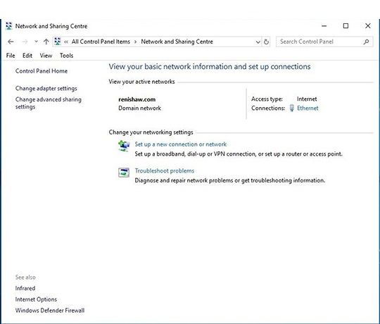
UCC S5 REVO-2 CMM controller installation guide

www.renishaw.com

Enviromental conditions
Indoor use                                                              IP30* (BS EN60529:1992)
Altitude                                                                Up to 2000 m
Operating temperature                                                   +5 °C to +50 °C
Storage temperature                                                     ‐25 °C to +70 °C
Relative humidity                                                       80% maximum ﴾non‐condensing﴿ for temperatures up to +31 °C
                                                                        Linear decrease to 50% at +50 °C
Transient voltages                                                      Installation category II
Pollution degree                                                        2

          * NOTE: It may be necessary to house UCC S5 in a suitable enclosure according to the installation's environmental conditions to
          obtain a higher IP rating.

Issued 07 2021                                                                                                                        7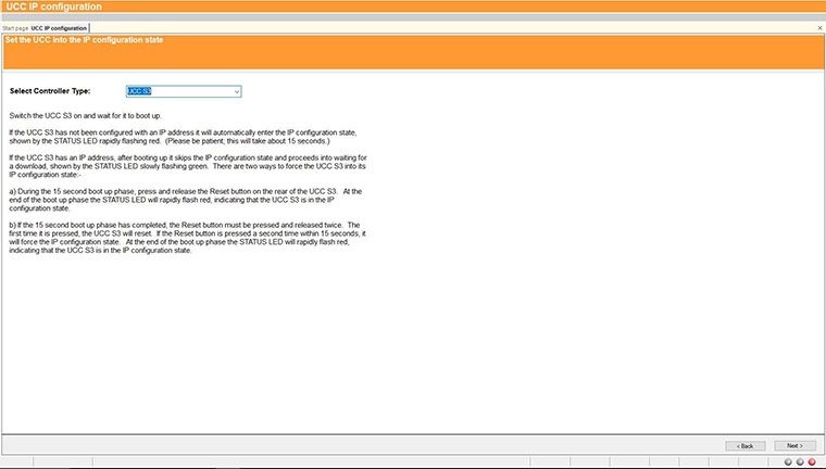
UCC S5 REVO-2 CMM controller installation guide

www.renishaw.com

References and associated documents
It is recommended that the following documentation is referenced when installing the UCC S5:

Renishaw documents
 Title                                                                   Document number
 Installation guide: REVO-2                                              H-1000-7590
 Installation guide: SPA3                                                H-1000-7566
 Installation and user's guide: MCU                                      H-1000-5182
 UCCassist-2 help                                                        Found within UCCassist-2

These can be all downloaded from www.renishaw.com/cmmmanuals.

External documents
National and international standards including the following may be applicable to the finished machine or installation: -

EN 292-2:1991 (Safety of machinery - Basic concepts, general principles for design - Part 2: Technical principles and specifications.

EN (IEC) 60204-1:1997 (Safety of machinery - Electrical equipment of machines - Part 1: General requirements).

Issued 07 2021                                                                                                                          8

UCC S5 REVO-2 CMM controller installation guide

www.renishaw.com

Introduction
The UCC S5 is the latest generation Renishaw CMM controller product and supports the second generation REVO-2 measurement head.

Issued 07 2021                                                                                                               9
UCC S5 REVO-2 CMM controller installation guide

www.renishaw.com

 Key                                   Description                           Key                                  Description

 1                                     Machine motors                        5                                    UCC S5 and power amplifier
                                                                                                                  SPA3 - these connect to the
                                                                                                                  machine cabling
 2                                     Machine scales and readheads          6                                    MCU joystick - MCUlite-2, MCU5,
                                                                                                                  MCU5-2, MCU W, MCU W-2 -
                                                                                                                  connects to SPA3
 3                                     Probe head - REVO-2 connects to 7                                          PC - connects to UCC S5 via an
                                       UCC S5 via the orange machine                                              ethernet cable
                                       cabling
 4                                     UCCassist-2 commissioning
                                       software and application
                                       software

The UCC S5 comprises a controller in a 19 inch rack-mountable enclosure. It is coupled to the CMM host computer by an Ethernet link and to
the CMM via external cable interface connectors.

The UCC S5 controller has the capability to:

     control three axes of a CMM (accepting digital readhead signals and generating three axes drive motor control signals)
     accept input signals from emergency stop, air pressure, crash detector, digital SPA, amplifier faults and all axis inner and outer travel limit
     switches
     accept two uncommitted general purpose input signals and generate one uncommitted general purpose output signal
     interface REVO-2
     directly support one or two Renishaw SPA3 servo power amplifiers (two SPA3 units will be required for machines with additional axes i.e.
     dual drive, rotary table)
     directly support the Renishaw TEC (16 channels) and RS232 (Mitutoyo) TEC systems
     provide a +24 V supply for use by the CMM switches

The UCC S5 supports the MCUlite-2, MCU5, MCU5-2, MCU W and MCU W-2 joysticks through the SPA3.

This guide gives information on physical installation, system connections and communications, as well as assistance in fault finding during the
installation of the UCC S5.

           WARNING: UCC S5 is not compatible with PH9, PHS, PH10 and the previous REVO systems. No attempt should be made to
           connect these system components to the UCC S5 as this will result in damage to the product or attached equipment.

Please use this guide in conjunction with the REVO-2 user's guide in order to fully understand the system's features, capabilities and
operation.

The UCC S5 must be used in conjunction with a Renishaw SPA3. Setup and commissioning should be completed through Renishaw's
UCCassist-2 software.

The UCC S5 uses an external power supply and manages full control of the REVO-2 head, CMM and probe signals and communicates with the
CMM's computer.

Issued 07 2021                                                                                                                               10
UCC S5 REVO-2 CMM controller installation guide
www.renishaw.com
Front panel
UCC S5
Rear panel layout
Key Description Key Description
1 37-way D-type plug for 7 Reserved
temperature compensation
2 Ethernet communications 8 Reserved
connector to CMM computer
3 Reset button 9 15-way D-type socket for REVO-
2 connection
4 Reserved - (USB type B socket) 10 Equipotential bond point
5 RJ45 connector to SPA3 11 DC power jack 48 V
6 RJ45 connector to second SPA3 12 DC power jack 24 V
(not implemented at this time)
Issued 07 2021 11UCC S5 REVO-2 CMM controller installation guide www.renishaw.com Installation Dimensions Width Depth Height Weight 440 mm (17.3 in) 180 mm (7.1 in) 44 mm (1.7 in) 2.1 kg (4 lb 10 oz) UCC S5 can either be free standing or used in a 19 inch rack system. Stand-alone installation The UCC S5 unit draws air from the right hand side when viewed from the front and expels air out of the left hand side. A minimum clearance gap of 10 mm is necessary between the sides of the unit and any potential obstruction. Issued 07 2021 12
UCC S5 REVO-2 CMM controller installation guide

www.renishaw.com

Mounting in a 19 inch rack
The rack mounting kit ﴾part number A‐5518‐0005﴿ contains two brackets and four M5 × 6 mm screws.

Assemble the brackets to the UCC S5 as shown below:

Cable lengths
UCC S5 to SPA3 connection
The units are linked via a CAT 5 or STP/ FTP cable. 300 mm cables are supplied with the SPA3 kits. It is not recommended to use a cable over
400 mm.

Ethernet cable link to PC
This is a standard ethernet CAT 5 cross-over cable and a 5 m cable is supplied as part of the UCC S5 kit. Lengths up to a maximum of 20 m
can be used.

Issued 07 2021                                                                                                                       13
UCC S5 REVO-2 CMM controller installation guide

www.renishaw.com

General wiring standards
To achieve reliable operation of the UCC S5 and the CMM's host computer, the following points should be observed:

   All signal cables MUST be screened and all cable screens must be connected electrically to the metal shells of the cable connectors
   It is recommended that cable screens should only be connected to the ground (via the connector shell) of the UCC S5 and SPA3
   To avoid earth loops, cable screens should not be directly attached to the CMM's protective earth
   The grounding must be continuous between the controller and all other equipment in the installation
   All cable connectors should be secured to the UCC S5 and SPA3 by the connector jack screws

          NOTE: The UCC S5 and SPA3 electronic zero volt rails are connected to their respective ground planes at star points within the
          UCC S5, the SPA3 and also to the protective ground of the ac supply.

Issued 07 2021                                                                                                                           14
UCC S5 REVO-2 CMM controller installation guide www.renishaw.com Reset button The rear panel reset button has two different functions. The function depends on the operational state of the controller. 1. Pressing and releasing the reset button within 15 seconds of switching on the unit will force the controller into IP configuration state. 2. Pressing and releasing the reset button after 35 seconds of switching on the unit will cause the unit to restart. To enter IP configuration state when the unit is already running the control software, press and release the reset button twice. Issued 07 2021 15
UCC S5 REVO-2 CMM controller installation guide

www.renishaw.com

System connection
Earth bonding scheme

Issued 07 2021                                    16
UCC S5 REVO-2 CMM controller installation guide

www.renishaw.com

Installation for up to 3 axes with head cable less than 25 m

Key                  Description                        Key    Description
1                    Orange head cable                  6      24 V power supply (supplied)
2                    Cat 5 300 mm cable (supplied)      7      25 V - 80 V power supply (not
                                                               supplied)
3                    16 / 0.2 mm earth connection       8      Air filter
4                    MCU connection                     9      48 V power supply (supplied)
5                    Cat 5 ethernet cable (5 m cross-
                     over cable supplied) to host PC

Issued 07 2021                                                                          17
UCC S5 REVO-2 CMM controller installation guide
www.renishaw.com
Installation for 4 - 6 axes with head cable exceeding 25 m and thermal effect
compensation (TEC)
Key Description Key Description
1 Orange head cable 7 25 V - 80 V power supply (not
supplied)
2 Cat 5 300 mm cable (supplied) 8 Air filter
3 16 / 0.2 mm earth connection 9 48 V power supply (supplied)
4 MCU connection 10 E-STOP link cable (supplied)
5 Cat 5 ethernet cable (5 m cross- 11 Head comms signal booster
over cable supplied) to host PC
6 24 V power supply (supplied) 12 TEC input
The REVO-2 head and CMM system are operated through UCCserver which uses I++DME command protocol to communicate between the
system application software and the UCC S5.
Full 5-axis scanning capability is achieved through interaction between the UCC S5, the REVO-2 and the SPA3, to co-ordinate all the motion
and metrology aspects across the three CMM axes and the two head axes.
Issued 07 2021 18UCC S5 REVO-2 CMM controller installation guide
www.renishaw.com
Head comms signal booster box installation
When using the Renishaw high-speed communications cable (orange cable) with Renishaw's 5-axis products, the maximum permissible cable
length is 25 m. Where runs of greater than 25 m are needed between the machine controller and probe head, a head comms signal booster
(HCSB) must be inserted. One HCSB is required for each additional 25 m of cable run.
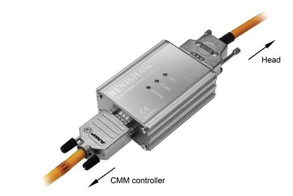
The HCSB is powered from the machine cable so does not require an additional power supply. It simply connects between two machine cables
as shown in the diagram below and can be attached to a suitable part of the machine structure if required.
Dimensions ﴾L × W × H﴿ 91 mm × 64 mm × 32 mm
Net weight 161 g
Power supply 20 Vdc supplied via machine cable
Connectors 15-way high-density 'D' type plug connects to cable from controller
15-way 'D' type socket connects to cable from head
Issued 07 2021 19UCC S5 REVO-2 CMM controller installation guide
www.renishaw.com
Cable connections
The cable connection to the head uses a standard 15-way high-density D connector. The cable should be connected and terminated as
detailed below. It is mandatory that the Renishaw universal machine cable is used.
Various lengths of cable are available and include pre-crimped options for ease of installation.
The following image shows the pin numbers for each connector end view of the Renishaw universal machine cable.
15-way HDD socket pin Function Core colour 15-way D plug pin number
number (quill) (controller)
11 Comms D+ Green 1
2 0V Black 2
1 Comms U+ Orange 3
7 0V White 4
13 Motor B0 Blue 5
3 +20 V Red 6
4 Motor A2 Grey 7
10 Motor A0 Pink 8
9 0V Inner screen * 9
12 Comms D- Green / black 10
6 Comms U- Orange / black 11
8 +20 V Clear 12
14 Motor B1 Violet 13
15 Motor B2 Yellow 14
5 Motor A1 Brown 15
Shell Outer screen Shell
* NOTE: In pre-crimped cables this will be yellow / green.
Ensure that the inner screen is not shorted to the outer screen at either end of the cable. A short can be prevented by using a small
piece of heatshrink or other suitable method.
Issued 07 2021 20UCC S5 REVO-2 CMM controller installation guide www.renishaw.com Preparation of Renishaw universal machine cable for quill mounted systems Preparation of Renishaw universal machine cable for shank mounted systems Issued 07 2021 21
UCC S5 REVO-2 CMM controller installation guide

www.renishaw.com

Temperature compensation connector

Pin number                          Channel                           Pin number                         Channel
1                                   Channel 1 input                   20                                 Channel 1 return
2                                   Channel 2 input                   21                                 Channel 2 return
3                                   Channel 3 input                   22                                 Channel 3 return
4                                   Channel 4 input                   23                                 Channel 4 return
5                                   Channel 5 input                   24                                 Channel 5 return
6                                   Channel 6 input                   25                                 Channel 6 return
7                                   Channel 7 input                   26                                 Channel 7 return
8                                   Channel 8 input                   27                                 Channel 8 return
9                                   Channel 9 input                   28                                 Channel 9 return
10                                  Channel 10 input                  29                                 Channel 10 return
11                                  Channel 11 input                  30                                 Channel 11 return
12                                  Channel 12 input                  31                                 Channel 12 return
13                                  Channel 13 input                  32                                 Channel 13 return
14                                  Channel 14 input                  33                                 Channel 14 return
15                                  Channel 15 input                  34                                 Channel 15 return
16                                  Channel 16 input                  35                                 Channel 16 return
17                                  Reserved                          36                                 Reserved
18                                  Reserved                          37                                 Reserved
19                                  Reserved                          Shell                              GND

The thermistors for each channel connect between the CH input and CH return numbers. The return signals are NOT zero volts and MUST
NOT be connected to any zero volt signal, GND or screen.

          NOTE: For more information regarding the set up and usage of axis and work piece sensors, please read the temperature
          compensation page of this installation guide.

Issued 07 2021                                                                                                                    22
UCC S5 REVO-2 CMM controller installation guide
www.renishaw.com
Connecting the UCC controller
Hardware connection
The host PC must have a dedicated ethernet connection to the UCC controller. It is recommended that this is NOT a USB plug-in adapter
because of the reduction in speed of operation these devices normally produce.
If the host PC is also to be connected to a network, it is necessary to install additional hardware within the host PC to permit a dedicated
connection to be available for UCC controller communication. For details on how to install additional hardware into the host PC, please refer
to the PC's installation / users guide.
The UCC controller is capable of using both 10 Mbps and 100 Mbps ethernet. The selection is determined by the capability of the network
adapter to which it is connected. It is recommended that a 100 Mbps network adaptor is used.
A 5 m Cat 5e cross-over ethernet cable is provided for this link as part of the UCC controller kit. Other lengths may be used, but the maximum
is governed by the generic specification for ethernet connections (i.e. a hundred metres) which is sufficient for any CMM installation.
If there are concerns about EMC disruption due to the environment, or the routing of the cable, then the using a shielded cable is
recommended.
It is suggested that the cross-over cable is labelled as a cross-over cable looks identical to a normal ethernet cable.
Software installation
The UCCassist-2 software must be installed on the host PC prior to connection of the UCC controller.
The latest version of UCCsuite can be downloaded from the Renishaw website for anyone with a MyRenishaw account. UCCsuite will install
UCCassist-2 and UCCserver to enable the hardware set-up.
After the software has been installed, one of the utility sequences available is “IP Configurer” which is used to give the UCC controller an IP
address and establishes the pairing of the PC and the UCC controller.
Configuration of IP addresses
This section describes the steps needed to connect the UCC controller to the host PC and configure the ethernet communication link.
NOTE: The examples used in this section are for Windows10 Professional and will vary for other operating systems.
Issued 07 2021 23UCC S5 REVO-2 CMM controller installation guide
www.renishaw.com
IP addressing
Choose an IP address for the UCC controller and an IP address for the PC's network adaptor that are of the same class:
class A 1.0.0.1 – 126.255.255.254 For class A networks, a network is defined by the first number.
class B 128.0.0.1 – 191.255.255.254 For class B networks, a network is defined by the first two numbers.
class C 192.0.0.1 – 223.255.255.254 For class C networks, a network is defined by the first three numbers.
NOTE: The last number must not be 0 or 255.
If there is more than one network connection in the PC, choose a network class for the UCC - PC connection that is not currently in use to keep
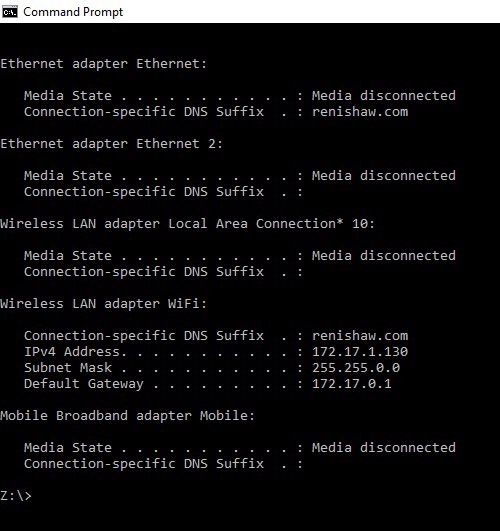
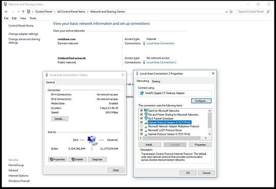
the connections clearly separate. To find out which IP address the other network interfaces use, bring up the command prompt, then type
“ipconfig”. Its output will look similar to this:
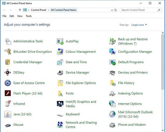
Issued 07 2021 24UCC S5 REVO-2 CMM controller installation guide www.renishaw.com Setting the IP address of the PC The process to set the IP address on the PC varies with each version of Windows. Administrator rights are needed in order to perform this operation. a) Navigate to 'Control Panel', then select 'Network and sharing centre': b) Select 'Ethernet' in 'Access type connections': Issued 07 2021 25
UCC S5 REVO-2 CMM controller installation guide

www.renishaw.com

c﴿ Click on 'Properties' and select ‘Internet Protocol ﴾TCP/IPv4﴿' and click 'Properties'.

d﴿ Select ‘Use the following IP address' and type in the IP address to use for the PC end of the comms link. Click in the Subnet mask field. On
Windows10 the Subnet mask will already be filled in. If you have to fill it in for yourself, here are the values:

 Class of network IP address belongs to                                     Subnet mask to use
 A                                                                          255.0.0.0
 B                                                                          255.255.0.0
 C                                                                          255.255.255.0

Leave the 'Default gateway' field blank.

Example:

Issued 07 2021                                                                                                                          26
UCC S5 REVO-2 CMM controller installation guide

www.renishaw.com

e) Click 'OK' and then 'OK' again. On earlier versions of Windows the PC needs to be rebooted.

Setting the IP address of the UCC controller
The UCC controller is not intended to be used on a corporate network. It is extremely important that the setting of the IP address of the UCC
controller is on a dedicated connection. It is also important that the connection is not “firewalled” at the PC end. Administrator rights are
needed in order to perform this operation.

Turn on the UCC controller and press the reset button (within 15 seconds), then wait for it to boot up.

          NOTE: This will take about 15 seconds.

It will enter its IP configuration state, shown by the 'Error' LED flashing rapidly.

Now start UCCassist-2 and the UCC IP configuration utility or commissioning sequence on the PC.

a﴿ Login to UCCassist‐2 → Go to 'Utilities bar' → Select 'IP Configure':

Issued 07 2021                                                                                                                         27
UCC S5 REVO-2 CMM controller installation guide www.renishaw.com b) Pressing 'Next' will bring up a screen to allow the specific controller to be selected. It will also give instructions on getting the controller into IP configure mode depending on if it has already been configured or has no current configuration. c) Click on the drop-down icon and select the IP address of the network adapter into which the UCC controller is plugged (this should be the one on which the IP address was set in 'Setting the IP address of the PC'). Issued 07 2021 28
UCC S5 REVO-2 CMM controller installation guide

www.renishaw.com

d) The UCC controller does not have an IP address. Type in the relevant address to match the network adapter in the PC. In the case below this
is 10.0.0.1:

e) Fill in the desired IP address. The IP configuration software has given you a head start by filling in the network part of the address
appropriate for the network adapter selected (see section 'IP addressing' for a discussion of the choice and of IP addresses in general).

Issued 07 2021                                                                                                                              29
UCC S5 REVO-2 CMM controller installation guide

www.renishaw.com

f﴿ Click on ‘Configure PC and UCC pair'. If all is well this will result in the address being applied to the controller and the IP configure screen
will close. If the controller is already configured a dialogue box saying the UCC is configured will open. Click 'Next' to finish.

          NOTE: Whenever one of the items in this pairing is changed, e.g. by connecting a different UCC controller to the PC, the UCCassist-
          2 IP configuration software must be re-run to establish the new UCC controller to the PC system.

Issued 07 2021                                                                                                                               30
UCC S5 REVO-2 CMM controller installation guide www.renishaw.com Changing the IP address of the UCC If the UCC controller already has an IP address, after booting up it skips its IP configuration state and proceeds into waiting for a download, shown by the status LED flashing slowly. There are two ways to force the UCC controller into its IP configuration state: a) During the 15 second power up phase, before the error LED comes on, press and release the 'Reset' button on the rear of the UCC controller. At the end of the power up phase the error LED will flash rapidly indicating it is in the IP configuration state. b) If the UCC controller has already powered up with the error light flashing slowly, i.e. about once per second, or even if the control software has been downloaded, the reset switch will need to be pressed twice. The first time to reset the controller then a second time, within 15 seconds, to force the IP configuration state. The UCC controller is now in its IP configuration state, and the UCCassist-2 IP configuration software can be run on the PC, selecting the appropriate network adapter required. The current IP address of the UCC controller will be displayed. Type in the new one and click on ‘Configure PC and UCC pair'. Establishing a new UCC - PC pairing If a different UCC controller is connected to the PC, or a different PC to the UCC controller or even if the network settings on the PC are modified, ensure that they are a matched pair. To do this, go through the procedure in the 'Setting the IP address of the PC' section, even if you do not wish to change the IP address of the UCC controller (if the IP address is already suitable, then you do not need to re-type it). Clicking on ‘Configure PC and UCC pair' will establish the new pairing. Downloading The name of the downloadable file is specific to the controller so the correct controller needs to be selected to select the correct downloadable. Other controller downloadables will not work on a different controller. Remember to change the name in any configuration settings appropriate for the front-end. The UCC controller system should now be established. Issued 07 2021 31
UCC S5 REVO-2 CMM controller installation guide

www.renishaw.com

Temperature compensation
          NOTE: Thermal compensation is activated and setup through UCCassist-2.

Axis sensors
Axis sensors are required to monitor and compensate for any temperature changes within the CMM's scale. The axis sensor is housed in a
potted ring terminal with a Ø3.7 mm hole which can be screwed or glued in position using a thermally conductive glue. The axis sensors are
supplied with a 200 mm cable (attached) with a male JST connector fitted to the end. The mating part of the connector is supplied as part of
the axis sensor kit.

Workpiece sensors
Workpiece sensors are required to monitor and compensate for any temperature changes of the workpiece material. They can be
magnetically mounted or clamped to the workpiece. The sensors are housed in a Ø20 mm aluminium body with a polyacetal sleeve. The
sensors should always be handled by the polyacetal sleeve in order to reduce any thermal effects. The sensors are supplied with a cable length
of 2000 mm and have a LEMO connector fitted. The mating part of the connector is supplied as part of the workpiece sensor kit in either panel
mount or in-line form.

Issued 07 2021                                                                                                                       32
UCC S5 REVO-2 CMM controller installation guide
www.renishaw.com
Pin allocation:
With the red dot on the LEMO pointing upwards:
‘Pair A' ‐ Top left pin and bottom left pin
‘Pair B' ‐ Top right and bottom right
NOTE: Ensure the sensor is connected to the controller with one pin from ‘pair A' and one pin from ‘pair B'.
Sensor resistance checks
A resistance check test is recommended:
During system installation once all sensor cabling has been completed
After every hardware change to the system (e.g. sensor, cable or switch change)
Every six months, after the system has been commissioned, to check for any sensor failure or cabling issues
Resistance check procedure
Regulate the temperature of the CMM room to a constant temperature between 16 °C and 28 °C
Allow the CMM to stabilise thermally for a minimum of one hour
Measure the sensor resistance from the 37-way D-type socket that the sensors are wired into. This is the resistance that the UCC measures
(cable plus sensor resistance).
All workpiece and axis sensor resistance measurements should be within the range of 8.4 kΩ < R < 15.7 kΩ
Best practise for using the thermal compensation system
Ensure the CMM is not subjected to unnecessary changes in temperature (fans blowing, close to radiator, in direct sunlight or any other
powerful radiant sources)
Excessive humidity should be avoided
Use the system as close as possible to the calibrated temperature
Renishaw recommends that workpiece and axis sensors are verified at six month intervals
Issued 07 2021 33UCC S5 REVO-2 CMM controller installation guide
www.renishaw.com
Workpiece sensor
Ensure the workpiece sensor is in full contact with the workpiece
Aim to position the workpiece sensor in the middle of the workpiece or near where the measurement is taking place
Electrically ground the workpiece prior to using the thermal effect compensation system to avoid electrostatic discharge (ESD) through the
workpiece sensor
Use multiple sensors for large workpieces
Handle the workpiece sensor by the white sleeve if possible or wait for five minutes once the sensor is in position before proceeding to
take a measurement
Keep the workpiece sensor cabling away from moving sections of the CMM
NOTE: It is not recommended to run axis thermal compensation without workpiece compensation (where axes and workpiece are
at the same temperature) as it is unlikely that reliable results will be obtained.
Axis sensors
Ensure the sensors are mounted as close as possible to the axis scales
It is recommended to have at least two sensors per axis to account for temperature gradient effects
On large or high specification CMMs, use more than three sensors per axis
Thermally conductive glue should be used when gluing axis sensors to an axis
All axis sensor cabling must be tightly secured to the axis body to prevent it getting trapped during moves
System accuracy and calibration
The TEC system can be used without calibration. The system accuracy is ±0.2 °C over the range 10 °C to 50 °C.
Issued 07 2021 34UCC S5 REVO-2 CMM controller installation guide www.renishaw.com Testing and verification The machine manufacturer or the installer of the UCC S5 is responsible for ensuring that the following testing and verification is performed to the appropriate standard: Verification that the electrical equipment is in compliance with the technical documentation Continuity testing of the protective bonding circuit Insulation resistance tests Functional tests, particularly those related to safety and safeguarding System performance Advisory It is recommended that periodical metrology tests are performed in order to identify any faults in subsystems e.g. air bearings, structure, cables, software etc. Issued 07 2021 35
UCC S5 REVO-2 CMM controller installation guide

www.renishaw.com

Troubleshooting
UCC S5 visual diagnostics
A visual indication of the system status provided by a multicoloured LED on the front panel. The LED provides assistance in diagnosing system
faults.

LED status key:
 LED                                                                   Description
                                                                       LED on

                                                                       LED flashing off / on

                                                                       LED flashing green / red

                                                                       LED off

                                                                       LED flashing red / blue

Issued 07 2021                                                                                                                      36
UCC S5 REVO-2 CMM controller installation guide
www.renishaw.com
LED Description
No LED - no power to UCC S5
Continuous LED - problem with comms link - reboot UCC S5 and
configure IP
Slow flash - waiting for download
Continuous light - download successful
Fast flash (5 Hz) - IP configuration mode
Slow flash - controller booting
Internal timeout - reboot UCC S5
REVO-2 head has problem - DSP watchdog triggered
REVO-2 head has problem - overcurrent detected
Fast flash (5 Hz) - communications error - reboot required
Slow flash - scale error - reboot required
Slow flash - problem with download - reboot required (check file
type)
Continuous LED - UCC S5 overheated
Slow flash - unit does not have controller ID - return to Renishaw
Fast flash (5 Hz) - no controller ID in IP configuration mode - return
to Renishaw
Fatal faults
Situations can occur that make it inadvisable or dangerous to continue using the CMM servo system. These are known in this document and
UCCassist-2 as fatal faults. A list of fatal faults are shown below and will be indicated through the user's software (for example UCCserver):
A report of the emergency stop switch being active
Air pressure is too low
Crash switch operated, if fitted
A scale reading failure
An indicated overspeed (calculated from the rate of change of position)
Outer limit switch active
NOTE: Other faults not classed as fatal can prevent the CMM's operation.
Issued 07 2021 37UCC S5 REVO-2 CMM controller installation guide
www.renishaw.com
Motors will not engage / re-engage
Symptoms
Either the servo drives will not engage when the controller has been sent the ‘engage' command, or the drives have disengaged automatically
and will not re-engage.
Possible causes (or reported causes)
After the unit is switched on and before the system is allowed to engage, it must be configured for motion (i.e. the machine, servo and move
parameters must be sent to the controller).
Any of the 'fatal faults' will prevent the system from engaging. In addition, the following will disengage the servo motors:
A reported failure from a servo power amplifier (amplifier feedback signal)
SPA being incorrectly configured.
The absence of the feedback signal from the motor contactor
The following list can also inhibit drive engagement or re-engagement
The probe being deflected
Any inner limit switch being operated or a soft limit exceeded
Tests / cures
UCCassist-2 can be used for further help with this by displaying the system status, the status bytes and signals.
The amplifier and motor contactor feedback signals can also be examined using the ‘input signals' window in UCCassist‐2.
NOTE: A scale error will cause the UCC S5 to enter an error state which is not recoverable within a metrology application
environment. If a scale error occurs it will be necessary to reinitialise the installation due to the possibility of lost scale counts and
metrology being affected.
Issued 07 2021 38UCC S5 REVO-2 CMM controller installation guide
www.renishaw.com
Maintenance
WARNING: Maintenance should only be carried out after the machine has been isolated from the electrical supply, compressed air
supply or other energy sources in accordance with the machine manufacturer's instructions.
Periodically check that all mounting screws and electrical connectors are securely tightened. Electrical safety checks should include inspecting
the mains cable for damage and the safety of the connections. Periodical safety checks should also include the function of the emergency stop
system, including operation of all switches integrated into the system. After operating the emergency stop system, the servo amplifier system
should be checked to ensure servo power can be engaged.
Advisory
It is recommended that periodical metrology tests are performed in order to identify any faults in subsystems eg air bearings, structure,
cables, software etc.
Cleaning
Cleaning should be carried out with a lint free cloth on outer surfaces only as the unit is not sealed against liquid.
Filter replacement
Positive air flow is employed within the enclosure for cooling purposes. This equipment has a replaceable filter to protect it from the ingress
of dust. The machine operator should inspect the condition of the filter on a regular basis. It is recommended that the filter is removed and
checked / replaced as necessary during the machine installer or retrofitter's regular maintenance routine.
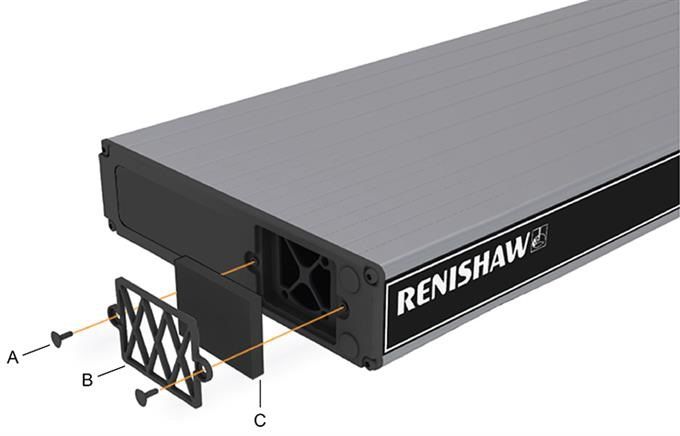
Exchanging / removing the air filter
The following procedure is recommended when exchanging / removing the air filter:
1. Isolate the controller via the ac power.
2. Remove the 19 inch rack mounting brackets (if fitted) by removing the two fixing screws on each side.
3. Pull both the filter retaining clips [A] away from the unit, this should permit the external filter cover [B] to be removed.
4. Remove the filter material [C] from the filter recess (replacement part number of filter is A-5518-0011).
5. Refit the filter cover and mounting brackets in the reverse order above.
Issued 07 2021 39UCC S5 REVO-2 CMM controller installation guide
www.renishaw.com
NOTE: There are no user serviceable parts inside this unit.
Issued 07 2021 40Renishaw plc T +44 (0)1453 524524
New Mills, Wotton-under-Edge F +44 (0)1453 524901
Gloucestershire, GL12 8JR
United Kingdom www.renishaw.com/cmmsupport
For worldwide contact details,
please visit our main website at
www.renishaw.com/contact
Issued 07 2021You can also read