UMG 96-PA UMG 96-PAMID - Janitza
←
→
Page content transcription
If your browser does not render page correctly, please read the page content below
Power Analyzer

                                                                       UMG 96-PA
                                                                       UMG 96-PAMID
                                                                       (Up to Firmware 1.12)

                                                                       User Manual and Technical Data
                                www.janitza.com
Doc no. 2.061.015.3a 04/2019

                               Janitza electronics GmbH
                               Vor dem Polstück 6
                               D-35633 Lahnau
                               Support phone number +49 6441 9642-22
                               Fax +49 6441 9642-30
                               E-mail: info@janitza.com
                               Internet: http://www.janitza.com
UMG 96-PA / UMG 96-PAMID                                                    www.janitza.com

       TABLE OF CONTENTS

       1. Notes relating to the device and the user manual                                    6
          1. 1   Disclaimer6
          1. 2   Copyright notice                                                             6
          1. 3   Technical changes                                                            6
          1. 4   About this user manual                                                       6
          1. 5   Defective device/disposal                                                    7

       2. Safety8
          2. 1   Presentation of warning notices and safety instructions                      8
          2. 2   Danger levels                                                                8
          2. 3   Safety measures                                                              9
          2. 4   Qualified personnel                                                          9
          2. 5   Warranty in the event of damage                                              9

       3. Product description                                                                10
          3. 1   Incoming goods inspection                                                   10
          3. 2   EC declaration of conformity                                                10
          3. 3   Intended use                                                                10
          3. 4   Scope of delivery                                                           11
          3. 5   Additional scope of delivery for UMG 96-PA
                                                             MID
                                                                                              11
          3. 6   Available accessories                                                       11
          3. 7   Device description                                                          12
          3. 8   Measurement method                                                          12
          3. 9   Operating concept                                                           12
          3. 10 GridVis® network analysis software                                           12
          3. 11 Performance features                                                         13

       4. Design of the device                                                               14
          4. 1   Front view - display                                                        14
          4. 2   Rear view - location of the connections                                     15
          4. 3   Nameplates16

       5. Assembly17
          5. 1   Installation location                                                       17
          5. 2   Installation position                                                       17
          5. 3   Fastening17

       6. Network systems                                                                    18

2
www.janitza.com                                                     UMG 96-PA / UMG 96-PAMID

7. Installation18
   7. 1   Rated voltages                                                                 18
          7. 1. 1   Three-phase 4-conductor network with grounded neutral conductor      18
   7. 2   Disconnectors19
   7. 3   Supply voltage                                                                 19
   7. 4   Voltage measurement                              20
          7. 4. 1  Overvoltage20
          7. 4. 2  Frequency20
          7. 4. 3  Voltage measurement connection versions 21
   7. 5   Current measurement                              22
          7. 5. 1  Current direction                       23
          7. 5. 2  Summation current measurement           23
          7. 5. 3  Ammeter23
          7. 5. 4  Current measurement connection versions 23

8. Port and PC Connections                                                               24
   8. 1   Port versions                                                                  24
   8. 2   RS485 interface                                                                24
   8. 3   Shielding25
   8. 4   Termination resistors                                                          25
   8. 5   Bus structure                                                                  26

9. Digital Inputs and Outputs                                                            28
   9. 1   Digital inputs                                                                 28
          9. 1. 1    S0 pulse input                                                      28
   9. 2   Digital outputs                                                                29
   9. 3   LED status bar                                                                 29

10. Analog Output                                                                        30

11. Operation31
   11. 1 Key assignment                                                                  31
   11. 2 Measured value display “Overview”                                               31
   11. 3 Selection menu                                                                  31
   11. 4 Overview of main screens                                                        32

                                                                                                 3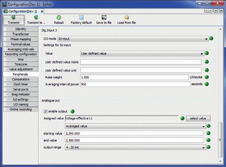
UMG 96-PA / UMG 96-PAMID                                           www.janitza.com

       12. Configuration34
          12. 1 Language34
          12. 2 Communication34
          12. 3 Measurement35
                12. 3. 1 Rated frequency                                             35
                12. 3. 2 Current transformer and voltage transformer / rated current 36
          12. 4 System38
                12. 4. 1 Firmware / serial number 38
                12. 4. 2 Time38
                12. 4. 3 Password38
                12. 4. 4 Reset39
          12. 5 Display41
          12. 6 Colors42
                12. 6. 1 Brightness42
                12. 6. 2 Standby42
                12. 6. 3 Brightness (standby) 42

       13. Commissioning43
          13. 1 Connecting supply voltage                                            43
          13. 2 Measured voltage                                                     43
          13. 3 Measured current                                                     43
          13. 4 Frequency44
          13. 5 Phase sequence                                                       44
                13. 5. 1 Principles of the pointer diagram                           45
          13. 6 Exceeding the measurement range                                      46
          13. 7 Checking the power measurement                                       47
          13. 8 Checking the communication                                           47
          13. 9 Delete min./max. Values individually                                 48
          13. 10 Harmonics48
          13. 11 Communication in the bus system 49
                 13. 11. 1 RS48549
          13. 12 Digital Inputs/Outputs                                              50
                 13. 12. 1 Digital inputs                                            50
                 13. 12. 2 Digital outputs                                           52
          13. 13 Analog output                                                       56
          13. 14 “Trailer pointer” function                                          57
                 13. 14. 1 Internal synchronization                                  57
                 13. 14. 2 External synchronization                                  58
                 13. 14. 3 Synchronization priority                                  60
          13. 15 Records61
          13. 16 Tariff switchover                                                   62

4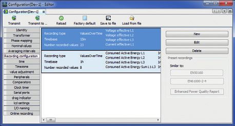
www.janitza.com                                                       UMG 96-PA / UMG 96-PAMID

14. UMG 96-PAMID                                                                           63
   14. 1 Intended use                                                                      63
   14. 2 Assembly63
   14. 3 Measured value display active energy                                              64
   14. 4 Secured load reading (meter reading) of the MID device                            64
   14. 5 Load profile                                                                      64
   14. 6 Log65
   14. 7 Password configuration                                                            65
   14. 8 Measured value display tariff                                                     65
   14. 9 Device acceptance report                                                          65

15. Overview Measured Value Displays                                                       66

16. Service and maintenance                                                                72
   16. 1 Repair and calibration                                                            72
   16. 2 Front film and display                                                            72
   16. 3 Service72
   16. 4 Device adjustment                                                                 72
   16. 5 Firmware update                                                                   72
   16. 6 Clock/battery73

17. Procedure in the event of errors                                                       74

18. Technical data                                                                         75

19. Function characteristics                                                               78
   19. 1 Modbus address list of the frequently required measured values:                   80
   19. 2 Number formats                                                                    81
   19. 3 Dimensional drawings                                                              82
   19. 4 Connection example 1                                                              83

                                                                                                   5
UMG 96-PA / UMG 96-PAMID                                                         www.janitza.com

       1.   Notes relating to the device and the user manual

       1.1 Disclaimer                                      1.4 About this user manual
       It is essential that the information products       Please send us any questions, comments or
       for the devices are observed to ensure safe         suggestions for improvement about the user
       operation and achieve the specified performance     manual via e-mail to info@janitza.de.
       characteristics and product features.

       Janitza electronics GmbH assumes no liability for                        NOTE
       personal injuries, property damage and financial    This user manual provides a description of the
       losses resulting from the failure to observe the    UMG 96-PA and UMG 96-PAMID devices and
       information products.                               information on how to operate the devices. It is
                                                           designated accordingly where provisions apply
       Make sure that your information products are        separately to each device or where they differ.
       legible and accessible.                             Observe the other applicable documentation
                                                           to your device in addition to this user manual,
       1.2 Copyright notice                                such as:
                                                           ··Installation instructions.
                                                           ··“GridVis® Software” Quick Start.
       © 2018 - Janitza electronics GmbH - Lahnau. All     ··“Safety Instructions” enclosure.
       rights reserved.
                                                           Where applicable, also observe the documents
                                                           relating to the expansion modules, such as
       Any duplication, processing, distribution and any   ··User manuals and
       other kind of use, even in part, is prohibited.     ··Installation instructions.

       All trademarks and any resulting rights belong to   Furthermore, the GridVis® software also has
       the respective holders of these rights.             its own “Online help”.

       1.3 Technical changes
       ··Make sure that the user manual matches your
         device.
       ··This user manual applies to the UMG 96-PA
         and UMG 96-PAMID. It is designated accordingly
         where provisions apply separately or differ.
         Observe chap. „14. UMG 96-PAMID“ on page
         63 In particular.
       ··First, make sure you have read and understood
         the document accompanying the product.
       ··Keep the documents accompanying the
         product accessible through its service life and
         hand them over to the subsequent owner where
         applicable.
       ··Refer to www.janitza.de for information
         concerning device revisions and the
         associated adjustments to the documentation
         accompanying the product.

6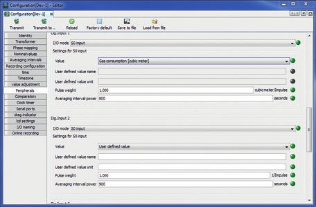
www.janitza.com                                UMG 96-PA / UMG 96-PAMID

1.5 Defective device/disposal
Before returning your defective devices
(components) to the manufacturer for inspection
(complete with accessories), please contact the
manufacturer’s support team first. Here, take the
transport terms and conditions into account.

                     NOTE
Please return any defective or damaged
devices to Janitza electronics GmbH. Observe
the shipping regulations for air freight and road
transport (complete with accessories).
Observe any special provisions relating to
devices with installed batteries or battery
packs!
Do not attempt to open or repair the device
(components) on your own, because if you do
so, the warranty rights will become void!

Please observe the national regulations for
the disposal of the device (the components)!
Dispose of individual parts, where necessary,
depending on the properties and existing
country-specific regulations, e.g. as:
··Electronic waste
··Batteries and accumulators
··Plastic
··Metal
or commission a certified disposal company with
the scrapping.

For more information on servicing and maintaining
your device, please refer to chap.„16. Service and
maintenance“ on page 72.

                                                                            7
UMG 96-PA / UMG 96-PAMID                                                              www.janitza.com

       2.   Safety

       Please read the present user manual and all           2.2 Danger levels
       other publications that are applicable for working
                                                             Warning notices and safety instructions are
       with this product. This applies in particular for
                                                             highlighted by a warning symbol and the danger
       installation, operation and maintenance.
                                                             levels are presented as follows depending on the
                                                             level of risk:
       In the process, observe all safety requirements
       and warning notices. Failure to observe the
                                                                                  DANGER
       notices can result in personal injury and/or
       damage to the product.                                Indicates an imminently dangerous situation
                                                             that will result in serious or fatal injuries in the
                                                             event of noncompliance.
       Any impermissible modification or use of this
       device exceeding the specified mechanical,
       electrical or other operating limits can result in                         WARNING
       personal injury and/or property damage.               Indicates an imminently dangerous situation
                                                             that can result in serious or fatal injuries in the
                                                             event of noncompliance.
       Read the user manual prior to first-time use of
       the device. Keep it throughout the entire service
       life of the device and always have it readily                               CAUTION
       available for reference.                              Indicates an imminently dangerous situation
                                                             that can result in minor injuries in the event of
       Also observe the applicable legal and safety          noncompliance.
       requirements for the respective application when
       using the device.                                                        ATTENTION
                                                             Indicates an imminently dangerous situation
       2.1 Presentation of warning notices and               that can result in property damage or
           safety instructions                               environmental damage in the event of
                                                             noncompliance.
       The warning notices listed below
       ··are used throughout the entire documentation.
                                                                                    NOTE
       ··can be found on the devices themselves.
       ··point out potential risks and dangers.              Points out procedures during which a danger of
       ··confirm information which clarifies or simplifies   injuries or property damage does not exist.
         procedures.

       The additional symbol on the device itself
       indicates an electrical danger that can result in
       serious injuries or death.

       The general warning symbol calls attention
       to possible risks of injury. Observe all the
       instructions listed under this symbol in order to
       prevent injuries or even death.

8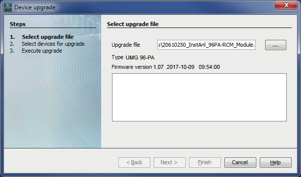
www.janitza.com                                                        UMG 96-PA / UMG 96-PAMID

2.3 Safety measures                                 2.4 Qualified personnel
When operating electrical devices, specific parts   To prevent personal injuries and property
of these devices inevitably carry dangerous         damage, only electrically qualified personnel
voltage. As a result, serious bodily harm or        may work on the devices and their components,
property damage can occur if they are not           modules, assemblies, systems and circuits. They
handled correctly:                                  must also have knowledge
                                                    ··of the national and international accident
                                                      prevention regulations.
                     WARNING                        ··of safety technology standards.
Risk of injury due to electric voltage!             ··in installation, commissioning, operation,
Serious personal injuries or death may occur!         enabling, grounding and labeling of electrical
Therefore, please observe the following:              equipment.
··Before starting work on your system,              ··of the requirements for personal protective
  disconnect the system from the power
  supply! Secure it against being switched            equipment.
  back on! Verify disconnection from power!         Electrically qualified personnel, in terms of
  Ground and short circuit! Cover or block off      the safety-related notes in all documents
  neighboring parts that are under voltage!         accompanying the device and its components,
··Also make sure to check the surrounding           are persons who can prove a professional
  area for dangerous voltage and switch it
  off if necessary during the operation and         qualification as an electrician.
  troubleshooting (especially with top hat rail
  devices)!
··For work on electrical systems, wear
  protective clothing and safety equipment                               WARNING
  according to applicable directives!               Warning against impermissible
··Before connection, ground the device/             manipulations or improper use of the device
  components at the ground wire connection,         or its components!
  if available!                                     Opening, dismantling or impermissible
··Do not touch exposed or stripped cores            manipulation of the device and its components,
  that are under voltage! Fit wire end ferrules     which exceeds the specified mechanical,
  on the conductors made of individual wires!       electrical or other operating limits, can result in
··Dangerous voltages may be present in              property damage or injuries up to death.
  all circuit parts connected to the voltage        ··Only electrically qualified personnel may
  supply.                                             work on the devices and their components,
··Secure the supply voltage with a suitable           assemblies, systems and circuits!
  circuit breaker/fuse!                             ··Always use your device or components as
··Never switch off, dismantle or manipulate           described in the associated documentation.
  safety devices!                                   ··Send the device or components back to
··There may still be dangerous voltages               the manufacturer in the event of visible
  present in the device or in the components          damage!
  even after disconnection of the supply
  voltage (capacitor storage).
··Do not operate equipment with open                2.5 Warranty in the event of damage
  current transformer circuits.
··Only connect screw-type terminals with the        Any impermissible manipulation or use of the
  same numbers of poles and same type!              device applies as "misuse" and/or "negligence"
··Do not exceed the threshold values stated         with respect to the product warranty and thus
  in the user manual and on the rating
  plate; this must also be observed during          voids the warranty for coverage of potentially
  inspection and commissioning.                     resulting damages. Observe chap. „3.3 Intended
··Safety instructions and warning notices in        use“ on page 10 for this.
  the documents that accompany the devices
  and their components!

                                                                                                          9
UMG 96-PA / UMG 96-PAMID                                                        www.janitza.com

       3.   Product description

       3.1 Incoming goods inspection                     3.3 Intended use
       The prerequisites for smooth and safe             The device is:
       operation of this device and its components       ··intended for installation in switching cabinets
       include proper transport, storage, setup and        and small installation distributors.
       assembly, operation and maintenance, as well      ··not intended for installation in vehicles! Using
       as observance of the safety instructions and        the device in mobile equipment is considered
       warning notices.                                    an unusual environmental condition and is only
                                                           permissible by special agreement.
       Exercise caution when unpacking and packing       ··not intended for installation in areas exposed
       the device, without using force and only using      to harmful oils, acids, gases, vapors, dust and
       suitable tools.                                     radiation, etc.
                                                         ··designed as an indoor meter.
       Perform a visual inspection of the device to
       ensure the fault-free mechanical condition.
                                                                               NOTE
       Please check the scope of delivery for            All screw-type terminals that belong to the
       completeness before beginning with the            scope of delivery are plugged into the device.
       installation of the device.
                                                                               NOTE
       If you assume that safe operation is no longer
       possible, the device must be shut down            All options and design versions supplied are
                                                         described on the delivery note.
       immediately and prevented from unintended
       re-commissioning. It can be assumed that
       safe operation is no longer possible, when, for   The following applies to the battery used in the
       example, the device:                              device:

       ··has visible damage,                                                 CAUTION
       ··no longer functions despite an intact power     Risk of injury due to fire or chemical burns!
         supply,                                         The batteries used in the device can lead to fire
       ··was subjected to extended periods of            or chemical burns if used improperly.
         unfavorable conditions (e.g. storage outside    ··Only replace batteries with the same types
                                                           or those recommended by Janitza!
         of the permissible climate thresholds without   ··Observe the polarity when installing the
         adjustment to the room climate, condensation,     battery!
         etc.) or transport stress (e.g. falling from    ··Remove batteries with non-conductive
         an elevated position, even without visible        tools only (e.g. plastic tweezers)!
         external damage, etc.).                         ··Do not recharge, destroy, heat up over
                                                           100 °C (212 °F) or burn batteries!
                                                         ··Do not dispose of batteries with household
       3.2 EC declaration of conformity                    waste! Observe the disposal requirements
                                                           in the respective device documentation!
       The laws, standards and directives applied for    ··Keep batteries away from children and
       the devices by Janitza electronics GmbH can         animals!
       be found in the EC declaration of conformity at   ··Send devices with soldered batteries
       www.janitza.de.                                     back to the manufacturer taking into
                                                           consideration the transport conditions in
                                                           the event of damage!

10
www.janitza.com UMG 96-PA / UMG 96-PAMID
3.4 Scope of delivery
Quantity Item no. Designation
1 52.32.001 1) UMG 96-PA
1 52.32.003 1) UMG 96-PAMID
1 33.03.360 Installation instructions
33.03.342 “Safety Instructions” enclosure.
1 33.03.361 “GridVis Software” Quick Start
1 10.01.896 Screw-type terminal, pluggable, 3-pole (auxiliary power)
1 10.01.849 Screw-type terminal, pluggable, 4-pole (voltage measurement)
1 10.01.871 Screw-type terminal, pluggable, 6-pole (current measurement)
1 10.01.909 Screw-type terminal, pluggable, 3-pole (RS 485)
Screw-type terminal, pluggable, 10-pole
1 10.01.865
(digital inputs and outputs, analog output)
1 52.22.251 Fastener set
1) For item number, see delivery note
3.5 Additional scope of delivery for UMG 96-PAMID
Quantity Item no. Designation
1 29.01.092 Terminal cover supply voltage
1 29.01.093 Terminal cover measurement
1 29.01.065 Silicone seal, 96 x 96
3.6 Available accessories
Quantity Item no. Designation
Battery type Lithium CR2032, 3 V
21.01.058
(Approval according to UL 1642)
29.01.065 Silicone seal, 96 x 96
15.06.015 Interface converter RS485 RS232
15.06.025 Interface converter RS485 USB
11UMG 96-PA / UMG 96-PAMID www.janitza.com
3.7 Device description 3.8 Measurement method
The device is suitable for The device measures
··Measurements and calculations of electric ··seamlessly and calculates all effective values
values such as voltage, current, power, within a 200 ms interval.
energy, harmonics in the building installation, ··the true effective value (TRMS) of the voltages
at distributors, circuit breakers and busbar and currents generated at the measurement
trunking systems. inputs.
··Measuring voltages and currents originating
from the same network. 3.9 Operating concept
··Measurements in low-voltage networks in
The measuring device’s operating concept
which rated voltages of up to 417 V conductor
consists of the following methods:
to ground and surge voltages of overvoltage
··6 function keys with display to configure and
category III occur.
record data.
··Measurements in medium and high-voltage
··The network analysis and programming
networks with current and voltage transformers.
software GridVis® for data programming and
Generally, current and voltage transformers
analysis.
perform measurements in medium and high
··The Modbus protocol and the Modbus
voltage networks!
address list for data configuration and export.
··Current measurement via external ../1 A or
You can find the Modbus address list on
../5 A current transformer.
www.janitza.de.
··Installation in permanently installed switch
cabinets or small installation distributors, in any
This user manual only describes the operation of
installation position.
the device via the 6 function keys. The GridVis®
··Use in residential and industrial sectors.
network analysis software has its own “Online
help” and e-learning modules.
The measuring device shows the measurement
results, whereas the measurement results are
3.10 GridVis® network analysis software
read and processed further via the interface.
Use the GridVis® network analysis software
ATTENTION available on www.janitza.de to program your
measuring device and to export data for analysis.
Malfunction or damage to the device due to To do so, connect a PC, for example via the
improper connection. serial interface (RS485) or a gateway (such as
Improperly connected devices can deliver
incorrect measured values or damage the UMG 512-PRO) to your measuring device.
device.
Please observe the following: Use the GridVis® network analysis software to:
··The measured voltages and measured ··Program your device.
currents originate from the same network. ··Configure and export recordings.
··Do not use the device to measure DC
current! ··Analyze the exported data.
··Ground conductive switchboards! ··Save the data in databases.
··Graphically illustrate the measured values.
··Program custom applications.
12www.janitza.com UMG 96-PA / UMG 96-PAMID
3.11 Performance features
General information
• Integrated front panel unit with the dimensions 96 x 96 mm
• Expansion with module technology
• Connection via pluggable screw terminals
• 320 x 240 px color graphics display
• Operation via 6 keys
• 3 voltage measurement inputs (600 V CAT III)
• 3 current measurement inputs (via current transformer)
• 3 digital outputs
• 3 digital inputs
(configured as pulse counter with simultaneous output calculation)
• 1 analog output (0 - 20 mA)
• Data storage 4 Mbyte flash drive
• RS485 interface (Modbus RTU, slave, up to 115 kbps)
• Recording of more than 2000 measured values
• Clock and battery
• Operating temperature range -10 °C – +55 °C
Measurement uncertainty
• Active energy, measurement uncertainty class 0.5S for ../5A transformer
• Active energy, measurement uncertainty class 1 for ../1A transformer
• Reactive energy, class 1
Measurement
• Recording of more than 800 measured values
• Measurement in TN and TT networks
• Measurement in networks with rated voltages up to L-L 720 Vrms and L-N 417 Vrms
(according to IEC)
• Current metering range 0.005 .. 6 Arms
• True effective value measurement (TRMS)
• Continuous scanning of the voltage and current measurement inputs.
• Frequency range of the power frequency 45 Hz .. 65 Hz
• Measurement of odd harmonics 1st through 25th for ULN and I.
• ULN, ULL, I, P (consumption/export), Q (ind./cap.)
• 2 rates (switchover via Modbus or digital input 1)
13UMG 96-PA / UMG 96-PAMID www.janitza.com
4. Design of the device
4.1 Front view - display
1
2
Fig. Front view of UMG 96-PA
3 8
4 7
5 6
1 Device type
2 Description of the function keys
3 Key 1: Configuration menu, back (ESC)
4 Key 2: Select number, mark check box ()
5 Key 3: Reduce number by 1, select menu item (), mark check box ()
6 Key 4: Increase number by 1, select menu item (), mark check box ()
7 Key 5: Select number, mark check box ()
8 Key 6: Open selection menu, activate input, confirm selection (Enter)
14www.janitza.com UMG 96-PA / UMG 96-PAMID
4.2 Rear view - location of the connections
2 3 4 5
1
6
8 7
Fig. Rear view UMG 96-PA
1 Supply voltage
2 RS485 interface
3 Digital inputs
4 Digital outputs
5 Analog output
6 Module connector
7 Current measurement inputs I1 to I3
8 Voltage measurement inputs V1 to V3
15PA UMG 96-PA UMG 96-PAMID
UMG 96-PA / UMG 96-PAMID www.janitza.com
4.3 Nameplates
UMG 96-PA
UMG 96-PA MID
UMG 96-PAMID (has two nameplates)
5 6 7 4 5 6 7
M 18
UMG96-PA-MID
0366
4 8 3
VDE-40048947 8
10H • 000 3 UMG 96xxx 10H • 000 9 2
XXX/XXXX 1234567 XXXX/XXXX 10 3 x 230/400 V . 0,01-1(6) A . 50 Hz . 2018
V . 4,5VA 2 Aux: 90..277V, 50/60Hz . 90..250V . 4,5VA 1 Cl.B . 10000 Imp/kWh . -10 °C...+55 °C
1 300V CAT III Janitza electronics GmbH
nitza.com Made in Germany • www.janitza.com 11 Vor dem Polstück 6 . D-35633 Lahnau 9
14 15
13 16
12
UMG 96-PA-MID 01A • 4 17
11
1234567 XXXX/XXXX 18
Aux: 90..277V, 50/60Hz . 90..250V . 4,5VA
10 300V CAT III
Made in Germany • www.janitza.com 19
Pos. Designation Description Pos. Designation Description
·· AC supply voltage in V ·· Voltage range in V
·· Rated frequency in Hz ·· Current range in A
1 (10) Operating data ·· DC supply voltage in V ·· Frequency range in Hz
·· Power consumption in VA 1 Operating data ·· Year of manufacture
·· Overvoltage category ·· Accuracy class
·· Pulse value in pulse/kWh
2 (11) Item number Item number of the manufacturer ·· Measurement temperature range
General danger symbol. 2 Single phase system Network system
Observe the warning notices
3 (12) “Danger sign” depicted on the device and listed 3 Three-phase system Network system
symbol in the documents in order to
prevent injuries or even death. 4 Device type Device designation
4 (13) Device type Device designation “MID active power” ·· Delivered
5 symbol ·· Purchased
5 (14) QR code Coded manufacturer data
6 CE mark See chap. 3.2 on page 10.
6 (15) Manufacturer logo Logo of the device manufacturer
Combined with the CE mark, is
7 CE mark See chap. 3.2 on page 10. 7 MID approval mark considered an MID conformity
mark (calibration mark).
8 (16) Manufacturer- Coded manufacturer data 8 VDE ID number VDE certification number
specific data
9 (17) Hardware version Hardware version of your device Manufacturer’s
9 Manufacturer’s address data
address
10 (18) Type/serial number Number for identifying the device
10-19 See table “Nameplate UMG 96-PA”
11 (19) Designation of Country of origin and web address
origin/web address of the manufacturer Table “Nameplate UMG 96-PA”MID”
Table “Nameplate UMG 96-PA”
16www.janitza.com UMG 96-PA / UMG 96-PAMID
5. Assembly
5.1 Installation location 5.3 Fastening
The device is suitable for indoor installation in Fasten the device using the side mounting
a stationary and weather-protected switch board. brackets inside the switchboard (mounting plate).
To this end, take the following steps:
Ground conductive switchboards! ··Before inserting the device, remove the
mounting brackets by applying horizontal lever
ATTENTION movement (with a screw driver, for example).
Property damage due to noncompliance with
the assembly instructions! Fig. Side view of UMG 96-PA
Non-observance of the assembly instructions with mounting brackets.
may damage or destroy your device.
··Observe the information for the installation
location in the “Assembly” and “Technical
data” sections.
··Ensure sufficient air circulation in your
installation environment and, where
applicable, sufficient cooling with high
temperatures!
5.2 Installation position
··Guide your device from the front through the
The cut-out size in the switchboard is switchboard (mounting plate).
92+0.8 mm x 92+0.8 mm. ··Fasten the brackets on the side of the device
by inserting and snapping them in.
Keep the following minimum distances to ensure ··Screw in the tensioning screws until they touch
sufficient ventilation: the mounting plate.
··The, apply two additional turns and carefully
tighten the tightening screws. Tensioning
screws that are tightened too firmly may
destroy the mounting brackets!
Mounting plate
Tensioning screw
Mounting
bracket
Screwdriver
Fig. Rear view of installation position of UMG 96-PA
If the tightening screws touch the mounting plate
apply no more than 2 additional turns to mount
the device
NOTE
UMG 96-PAMID : Observe the additional
information about assembly in section 14.2 on
page 63.
17UMG 96-PA / UMG 96-PAMID www.janitza.com
6. Network systems 7. Installation
Network systems and maximum rated voltages The UMG 96-PA is suitable for voltage
according to DIN EN 61010-1/A1: measurement in TN and TT systems.
The voltage measurement in the UMG 96-PA
Three-phase 4-conductor systems is classed in the overvoltage category 600V
with grounded neutral conductor CATIII(rated surge voltage 6 kV).
L1 L1 L1
L2 L2
WARNING
N N
Risk of injury due to electric voltage!
Do not short circuit secondary side connections
of voltage transformers! This can result in
R serious personal injuries or death. L2
··Connect voltage transformers according to
L3 L3
their documentation! L3
E E E E E
··Check your installation! E E
IEC UL-N / UL-L: 417 VLN / 720 VLL
UL UL-N / UL-L: 347 VLN / 600 VLL 7.1 Rated voltages
The device can be used in 7.1.1 Three-phase 4-conductor network
··TN and TT networks L1 with
L grounded neutral conductor
L1
··residential and industrial sectors.
Networks and rate voltages suitable for your
device: N
UL-N / UL-L
WARNING
66V / 115V
Risk of injury due to electric voltage!
L2 N
120V / 208V L2
Measurement Evoltage surges over E the approved
E E
127V / 220V E E
overvoltage category can damage insulation Maximum rated voltage of the network
in the device. The safety of the device will be 220V / 380V
impaired. This can result in serious personal 230V / 400V according to MID (UMG 96-PAMID)
injuries or death. 240V / 415V
··Only use the device in environments in 260V / 440V
which the permissible measurement 277V / 480V Maximum rated voltage of the
voltage surge can be observed. 347V / 600V network according to UL
400V / 690V
417V / 720V Maximum rated voltage of the
network
Fig. Suitable network rated voltages for measurement
inputs according to EN 60664-1:2003
L1 347V/600V 50/60Hz L1
L2
240V
L3 50/60Hz
N N
PE
V1 V2 V3 VN
AC/DC
4M
4M
4M
4M
DC
Grounding of
the system Voltage measurement
UMG 96-PA Auxiliary supply
Fig. Schematic diagram -
measurement in three-phase 4-conductor system.
18www.janitza.com UMG 96-PA / UMG 96-PAMID
L
7.2 Disconnectors N
Install a suitable disconnector for the supply PE/FE
voltage in the building installation in order to de-
1)
Functional ground
energize the device from current and voltage.
1) Fuse (UL/IEC-listed)
··Install the disconnector near the device in a 2) Disconnect device
location that is easily reachable for the user. (disconnector or circuit
··Mark the disconnector as a disconnecting 2) breaker)
device for this device.
Fig. Connection
7.3 Supply voltage example
“Supply voltage”
A supply voltage is required for device operation.
The type and level of the supply voltage for your
device can be found on the rating plate. Please
also observe the following:
··Before connecting the supply voltage, ensure
that the voltage and frequency correspond to
the specifications on the nameplate.
··Connect the supply voltage an UL/IEC
approved fuse to the plug-type terminals on the
rear side of the device.
··After connecting the supply voltage, a screen
appears on the display. If no screen appears,
check whether the supply voltage is within the
rated voltage range. NOTE
Without functional ground, the device shows
a non-applied residual voltage.
WARNING
Risk of injury due to electric voltage!
Serious personal injuries or death can occur
due to:
··Touching live exposed or stripped cores.
··Device inputs that are dangerous to touch.
Before starting work, disconnect your
system from the power supply! Secure it
against being switched back on! Verify
disconnection from power! Ground and short
circuit! Cover or block off neighboring parts
that are under voltage!
CAUTION
Property damage due to noncompliance with
the connection conditions.
Noncompliance of the connection conditions
can damage or destroy your device.
Therefore, please observe the following:
··Observe the specifications on the
nameplate relating to voltage and
frequency!
··Connect the supply voltage via a fuse
pursuant to the technical data!
··Do not tap the supply voltage at the voltage
transformers!
··Provide a fuse for the neutral conductor
if the neutral conductor connection is not
grounded to the source!
19UMG 96-PA / UMG 96-PAMID www.janitza.com
Overcurrent protection device for the line The power frequency is calculated using the
protection of the supply voltage phase L1 measured voltage. The sampling
frequency of the voltage and current
Recommendation for the overcurrent protection measurement inputs is calculated based on the
device for line protection of the supply voltage power frequency.
(depending on the device versions):
··Option 230 V --> 6 - 16 A (Char. B) The frequency of the voltage power frequency
··Option 24 V *--> 1 - 6 A (Char. B) can no longer be calculated accurately while
measuring with severe voltage distortion. What
this means is that a fixed value should be
HINWEIS specified for the corresponding power frequency
*The 24 V option applies only to the UMG 96-PA! for measured voltages with severe voltage
distortion. Voltage distortions occur, for example,
when measuring consumers that are operated
Recommendation for the maximum number of with a phase angle control. Current distortions do
devices on one circuit breaker depending on the not have an impact on the determined frequency.
versions:
··230 V option:
For a B6A circuit breaker, a maximum of NOTE
4 devices. The MID device only supports an automatic
For a B16A circuit breaker, a maximum of frequency calculation (45 -65 Hz)!
11 devices.
··24 V option:
For a B6A circuit breaker, a maximum of More information can be found in chapter „12.3.1
3 devices. Rated frequency“ on page 35
For a B16A circuit breaker, a maximum of
9 devices.
NOTE
The fuse is only a line protection - is not device
protection!
7.4 Voltage measurement
The device has 3 voltage measurement inputs
(V1 to V3) that are on the rear side of the device.
7.4.1 Overvoltage
The voltage measurement inputs are suitable for
measuring in networks in which category 600 V 1.) Fuse
CAT III overvoltages can occur (rated surge 1) 1) 1) (UL/IEC listed)
voltage 6 kV). 2.) Disconnect device
2) 2) 2)
(disconnector or circuit breaker)
7.4.2 Frequency
L1
The device: L2
··requires the power frequency for the
L3
measurement and calculation of measured
values. N
··is suitable for measuring in networks in which Fig. Connection example for voltage measurement.
the power frequency of the voltage is in the
45 Hz to 65 Hz range.
20www.janitza.com UMG 96-PA / UMG 96-PAMID
7.4.3 Voltage measurement connection versions
WARNING
Fig. Voltage measurement in the
Risk of injury due to electric voltage! three-phase 4-conductor
Non-observance of the connection conditions Voltage system
for voltage measurement inputs may result in V1 V2 V3 VN
severe injuries or death.
Therefore, please observe the following:
··Before starting work, disconnect your
system from the power supply! Verify that
there is no current!
··Use voltage transformers to connect Load
voltages exceeding the permitted rated line
voltages.
··The voltage measurement inputs on the
device are dangerous live parts!
··Attach a disconnector as described in Fig. Voltage measurement in the
section 7.2 on page 19. single-phase 3-conductor
··Use a UL/IEC approved overcurrent
Voltage system
V1 V2 V3 VN
protection device with a rated value that
is rated for the short-circuit current at the
connection point.
Load
CAUTION
Improper connection will cause the device to
malfunction.
Faulty measured values will result if the device Fig. Voltage measurement in the
is improperly connected. three-phase 4-conductor
Therefore, please observe the following: Voltage
V1 V2 V3 VN
system via a voltage
··Measured voltages and currents originate transformer
from the same line.
··The device is not suitable for measuring DC
current.
NOTE Load
·· The device only calculates measured values if
voltage L1-N is greater than 20 Veff (4-conductor
measurement) or voltage L1-L2 is greater than
34 Veff (3-conductor measurement) at voltage
Fig. Voltage measurement in the
measurement input V1. single-phase 2-conductor
··Use a line protection (1 - 10 A) with IEC/UL Voltage system
approval as fuse protection for the voltage V1 V2 V3 VN
measurement.
Load
21UMG 96-PA / UMG 96-PAMID www.janitza.com
7.5 Current measurement
WARNING
The device:
··is designed for the connection of current Risk of injury due to electric voltage on
transformers with secondary currents of ../1 A current transformers!
High voltage spikes that are dangerous to
and ../5 A. touch can arise on current transformers that are
··is only approved for a current measurement operated open on the secondary side, which
using the current transformer. can result in serious injuries or even death.
··does not measure DC currents. Therefore, please observe the following:
The default current transformer ratio is set ··Before starting work, disconnect your
system from the power supply! Verify that
to 5/5 A and may need to be adjusted to the there is no current!
current transformer used. ··Avoid open operation of the current
transformer.
··Short-circuit the unloaded current
transformer.
··Before interrupting the power supply, it
is critical to short circuit the secondary
connections of the current transformer.
··If a test switch is present that automatically
short circuits the secondary lines of the
current transformer, it is sufficient to
put it in the “test” position provided that
the short-circuiters have been checked
beforehand.
··Only use current transformers that have
a basic insulation according to
IEC 61010-1:2010.
··Fasten the attached screw-type terminal to
the device with the two screws.
·· Even safe open current transformers are
dangerous to touch if they are operated open.
··Observe the documentation for the current
transformers!
S1 S2 Load
L1
L2 S1 S2
WARNING
L3 S1 S2
Risk of injury due to electric voltage!
During high measured currents, temperatures
N
up to 80 °C can arise at the connections.
Fig. Example of “Current measurement via current Use lines which are designed for an operat-
transformer” connection ing temperature of at least 80 °C.
NOTE
WARNING
You can easily configure the current
Risk of injury due to electric voltage! transformer ratios via
Serious personal injuries or death can occur ··the device menu (Configuration >
due to: Measurement > Measurement).
··Touching live exposed or stripped cores. ··the GridVis® software.
··Device inputs that are dangerous to touch.
De-energize your system before beginning
to work! Check that there is no voltage!
Ground the system!
Use the ground connection point with the
ground symbol for this.
22www.janitza.com UMG 96-PA / UMG 96-PAMID
7.5.1 Current direction 7.5.4 Current measurement connection versions
You can correct the current direction for each
phase individually using the existing serial Fig. Current measurement via
the current transformer
interfaces. So, there is no need to subsequently in the three-phase
reconnect the current transformer in the event of 4-conductor system
an improper connection.
7.5.2 Summation current measurement Load
For a summation current measurement via
two current transformers, first set their total
transformation ratio on the device. A description
of how to set the current transformer ratios is
provided in chapter 12.3.2 on page 36.
Fig. Current measurement in the
Example: single-phase 3-conductor
The current measurement occurs via two current system
transformers. Both current transformers have a
transformation ratio of 1000/5 A. The summation Load
measurement is performed with a summation
current transformer 5+5/5 A.
The device must then be set as follows:
Primary current: 1000 A + 1000 A = 2000 A
Secondary current: 5 A
Fig. Current measurement via
Fig. Example for 2 current transformers in the
the current UMG three-phase 4-conductor
measurement I system
via a summation S1 S2
current transformer
Einspeisung 1 Einspeisung 2 Load
Supply 1 Supply 2
P1 P2
1S1 1S2 2S1 2S2
1P1 1S1 2S1 2P1
(K) (k) (k) (K)
(L) (l) (l) (L)
1P2 1S2 2S2 2P2
L1 Fig. Current measurement in the
Verbraucher A Verbraucher B single-phase 2-conductor
Consumer A Consumer B N system
Load
7.5.3 Ammeter
If you want to measure the current not only with
the UMG, but also with an ammeter as well,
switch the ammeter in series to the UMG.
Fig. Circuit diagram UMG NOTE
with additional I
ammeter S1 S2 If the measuring range is exceeded, the device
switched in series display shows the warning notice Measuring
A
range exceeded and specifies the current
and voltage path.
Einspeisung Verbraucher
Supply (k)S1 S2(l) Consumer
(K)P1 P2(L)
23UMG 96-PA / UMG 96-PAMID www.janitza.com
8. Port and PC Connections
8.1 Port versions 8.2 RS485 interface
There are various options available to connect The RS485 interface for this device is designed
the device to a PC: as a 3-pole plug contact and communicates via
1. Connection via an interface converter: the Modbus RTU protocol.
PC with GridVis® Recommended cable type:
··Unitronic Li2YCY(TP) 2x2x0.22 (Lapp cable).
UMG 96-PA
Connection capacity of the terminal:
··0.2 - 1.5 mm2
RS232
(see chapter “Technical Data”)
RS232 RS485
RS485
PC with GridVis®
e.g.: RS485 bus
Data GND
UMG 96-PA connection e.g.
A A connection of
to the UMG
additional
604 as a B B slave devices
gateway
(master)
USB
USB RS485
RS485
2. Use of the UMG 96-PA (slave) via an UMG
(master) using a Gateway function (such as
UMG 512):
PC with GridVis®
Fig. Fig. RS485 interface, 3-pole plug contact
RS485 bus
Data GND
A
120 Ω
B
Ethernet Ethernet
UMG 512-PRO
as gateway UMG 96-PA UMG 96-PA UMG 103
Slave 1 Slave 2 Slave 3
Fig. RS485 interface, 3-pole plug contact with
termination resistor (item no. 52.00.008)
Modbus Modbus Modbus
NOTE
CAT cables are not suitable for the bus wiring!
CAUTION Use the cable types recommended for this (see
above).
Property damage due to incorrect network
settings. A segment of an RS485 bus structure can
Incorrect network settings can cause faults in contain up to 32 participants/devices. Use
the IT network! repeaters to connect segments with more than
Consult your network administrator for the 32 participants/devices.
correct network settings for your device.
The device does not contain an integrated
termination resistor (see chap. „8.4 Termination
resistors“ on page 25).
24www.janitza.com UMG 96-PA / UMG 96-PAMID
8.3 Shielding 8.4 Termination resistors
For connections via the interfaces, provide The cable is terminated with resistors (bus
a twisted and shielded cable and observe the terminator, 120 Ω, 1/4 W) at the start and end of
follow points for the shielding: a segment.
··Ground the shields of all cables that lead into
the cabinet at the cabinet entrance. The device does not contain an integrated
··Connect the shield over a large area and with termination resistor.
good conductivity to a noiseless ground.
··Do NOT connect the shield to terminal C (GND) Correct
··Mechanically trap the cable above the
grounding clamp in order to prevent damage
caused by cable movement.
··Use appropriate cable entries for guiding the
cable into the switch cabinet, for example, PG Incorrect
glands.
Cable
Terminal strip in the switch cabinet.
Tension relief
Shielding braid Device with RS485 interface
of the cable (without termination resistor)
Grounding clamp Device with RS485 interface
Noiseless ground (With termination resistor on the device)
Fig. Shielding design at cabinet entrance.
WARNING
Transmission errors and risk of injury due to
electrical disturbance!
Due to atmospheric discharge, errors in the
transmission and dangerous voltages on the
device can arise.
Therefore, please observe the following:
··Place the shielding at least once on
functional ground (PE).
··If there is a greater source of interference
or the frequency converters are in the
switch cabinet, connect the shielding as
close as possible on the device to the
functional ground (PE).
··Adhere to the maximum cable length of
12000 m at a baud rate of 38.4 k.
··Use shielded cable.
··Lay interface lines separated or additionally
insulated from the system parts carrying
mains voltage.
25UMG 96-PA / UMG 96-PAMID www.janitza.com
8.5 Bus structure
In a bus structure ··Devices with an activated bus terminator must
··all devices are connected in line. be supplied with power.
··each device has its own address (see chap. ··Placing the master at the end of a segment is
„12.1 Communication“ on page 34). recommended. If the master is replaced with an
··up to 32 participants/devices can be activated bus terminator, the bus is deactivated.
interconnected in a segment. The cable is ··The bus can become unstable if a slave is
terminated with resistors (bus terminator, replaced with an activated bus terminator or is
120 ohm, 1/4 W) at the start and end of de-energized.
a segment. ··Devices, which are not subscribed to the bus
··Repeaters (line amplifiers) are used for more terminator, can be replaced without making the
than 32 subscribers to connect the segments. bus unstable.
Fig. Illustration of a bus structure
Master
T
T
Slave Slave Slave Repeater
T
T
Slave Slave Slave Slave
Speisung notwendig / power supply necessary Master - e.g. UMG 604-PRO
T Busabschluss eingeschaltet / bus terminator on Slave - UMG 96PA
26www.janitza.com UMG 96-PA / UMG 96-PAMID
27UMG 96-PA / UMG 96-PAMID www.janitza.com
9. Digital Inputs and Outputs
The device has External auxiliary
voltage 24V DC
··3 digital inputs and
··3 digital outputs. - +
UMG 96-PA 17
9.1 Digital inputs Digital inputs 1-3
The device has three digital inputs allowing 18
a connection, for example, to one signal each. 2k21 S1
LED
Digital
Input 1
If a signal is active, the corresponding LED is 2k21
illuminated green.
19
The device recognizes an input signal on the 2k21 S2
Digital
LED
digital input if Input 2
2k21
··A voltage of at least 18 V and no more than
28 V DC (typically at 4 mA) is applied.
··A current of at least 0.5 mA and no more than 20
6 mA is applied. 2k21
Digital S3
LED
Input 3
2k21
NOTE
Observe the polarity of the supply voltage. Fig. Example for connecting the external switching
contacts S1-S3 to the digital inputs 1, 2 and 3.
+
-
9.1.1 S0 pulse input
Every digital input is designed for connecting an S0
pulse generator according to DIN EN62053-31.
You require an external auxiliary voltage with
an output voltage in the range of 18 - 28 V DC
and a resistance with 1.5 kOhm.
External auxiliary
Fig. Port for digital inputs voltage 24V DC
- +
CAUTION UMG 96-PA 17
Digital inputs 1-3 1.5k
Transmission errors and property damage
due to electrical failure. 18
S0 Pulse
At a line length exceeding 30 m, there is a 2k21
LED
Digital generator
Input 1
likelihood of transmission errors and damage to 2k21
the device as a result of atmospheric discharge.
Use shielded lines for connecting to the
digital inputs and outputs! 19
2k21
Digital
LED
Input 2
2k21
20
2k21
Digital
LED
Input 3
2k21
Fig. Example for connecting an S0 pulse generator to
a digital input 1.
28www.janitza.com UMG 96-PA / UMG 96-PAMID
~
9.2 Digital outputs
The device has 3 digital outputs that
··Are electrically isolated from the analysis
electronics via an optical coupling.
··Have a common reference.
··Are not short-circuit proof.
··Require an auxiliary voltage. Fig. Port for digital/pulse outputs
··Can be used as pulse outputs. External auxiliary
··Can switch DC and AC loads. voltage 24V DC
··Can be controlled via Modbus. + -
··Can emit results from comparators.
UMG 96-PA
CAUTION
21
Property damage due to connection fault.
LED
The digital outputs are not short circuit proof! DC
Therefore, connection faults may cause Digital Ouput 1
22
K1
damage to the connections.
When connecting the outputs, ensure that
the wiring is correct.
LED
DC
Digital Ouput 2
23
K2
NOTE
LED
··Functions for the digital outputs can be
easily and clearly configured in the GridVis® Digital Ouput 3
24
software (see www.janitza.de).
··A connection between the device and the Fig. Connection example of two relays to the digital
PC is required via an interfaces for use of the outputs
GridVis software®.
UMG 96-PAMID: 9.3 LED status bar
··The function “MID active energy” is assigned
to digital output 1 (terminal 21/22) of the The LED status bar on the rear of the device
UMG 96-PA MID. The function “MID active shows the different input and output states.
energy” is allocated to Digital output 1 and
can be neither modified nor configured
otherwise! Digital inputs
Each LED assigned to the input is illuminated
in green if a signal of at least 4 mA flow at this
CAUTION interface.
Measurement errors when used as a pulse
output. Digital outputs
When using the digital outputs as a pulse Each LED assigned to the input is illuminated in
output, measurement errors may occur as green if the output is set as active - irrespective
a result of residual current. of any additional connection to this interface.
For the supply voltage (DC) of the digital
inputs and outputs, use a power adaptor
with a residual current below 5% of the
supply voltage. LED status bar LED status bar
Digital inputs Digital outputs
29UMG 96-PA / UMG 96-PAMID www.janitza.com
10. Analog Output
The device has one passive analog output
that can output a current of 0 - 20 mA. An
external power adapter (24 V DC) is required for
operation.
The connectable load must not exceed
a resistant of 300 ohm.
If the analog output is loaded with a higher
resistance, the output range (20 mA) is limited.
The measured value assigned to the analog
output, the start and end values and the output
range 4 - 20 mA or 0 - 20 mA must be set via the
GridVis® software (more information can be found
in chapter „13.13 Analog output“ on page 56)
-
=
+
Fig. Analog output connection
230 V AC
External operating
voltage 24 V DC
+ -
26
Analog inputs
25
+
UMG 96-PA
Analog output 1
30www.janitza.com UMG 96-PA / UMG 96-PAMID
11. Operation
The device is operated via six function keys, 11.2 Measured value display “Overview”
which, depending on the context, are assigned
Start screen UMG 96-PA:
various functions:
After the power returns, the UMG 96-PA starts
with the measured value display “Overview”.
··Selecting displayed measured values.
··Navigation within the menus.
Start screen UMG 96-PAMID:
··Editing device settings.
The UMG 96-PAMID starts with the measured
value display “MID active energy”.
1 This measure value display contains the device
name and an overview of important measured
values. In delivery state, the device name
2 consists of the device type and the serial number
of the device.
3 Pressing key 1 (Esc) several times branches out
the measured value display “Overview”!
4
Fig. 96-PA measured value display “Overview”
1 Display title
2 Measured values
3 Labeling of the function keys
4 Function keys
11.1 Key assignment
Key Function Fig. Measured value display “Overview”
··Selection menu 11.3 Selection menu
··Exit menu, back (Esc)
··Press several times: If you are in the measured value display “Overview”,
Back to measured value display open the main menu by pressing key 1 (Esc).
“Overview”
··Select number
··Set check box ()
··Change (number -1)
··Set check box ()
··Select menu item ()
··Change (number +1)
··Set check box ()
··Select menu item ()
··Select number
··Set check box ()
··Open selection menu
Fig. UMG 96-PA main menu
··Activate input
··Confirm selection (Enter)
Key 1 (Esc): Main menu
31UMG 96-PA / UMG 96-PAMID www.janitza.com
11.4 Overview of main screens
Main menu
Overview (start screen UMG 96-PA) Oscilloscope
Voltage L1
Voltage Voltage L2
Voltage L-N Voltage L3
Voltage L-L Voltage L1-3
Curve Current L1
Current L2
Current Current L3
Current Current L1-3
THD-I
Curve Pointer diagram
Power System
Total power Configuration
Active power Language
Reactive power Communication
Apparent power Field bus: Device address
Active power curve Field bus: Baud rate
Reactive power curve Field bus: Data frame
Apparent power curve Measurement
Measurement
Energy (& MID) Current transformer
Active energy (Only UMG 96 PA) Voltage transformer
Reactive energy Rated current
Apparent energy Rated frequency
Tariff System
MID active energy (Only UMG 96 PAMID
) Version
(Start screen UMG 96-PAMID) Serial number
Time
Usage overview Password
Active energy /month Reset
Reactive energy /month Display
Apparent energy /month Brightness
Active energy /day Standby after
Reactive energy /day Brightness (standby)
Apparent energy /day Colors
L1 voltage / current
Harmonic L2 voltage / current
Voltage L1 L3 voltage / current
Voltage L2 Overview COM ports
Voltage L3 Comparator 1
Current L1 Comparator 2
Current L2 Select menu:
Current L3 ·· Using keys 3 () and 4 () select the menu item.
·· Confirm this using key 6 (Enter).
·· Exit the selection with key 1 (Esc).
32www.janitza.com UMG 96-PA / UMG 96-PAMID
33UMG 96-PA / UMG 96-PAMID www.janitza.com
12. Configuration
To configure the device, connect the supply ··Confirm the selection using key 6 (Enter).
voltage. For this purpose, proceed as described ··Exit the configuration screen by pressing key 1
in 13.1 on page 43. (Esc).
··Press key 1 (Esc) to open the main menu. Select
NOTE the desired measured value display with keys 3
The configuration of the UMG 96-PAMID is () and 4 (). Confirm the selection with key 6
password protected (cf. „14.7 Password (Enter) or navigate directly to the measured value
configuration“ on page 65). display “Overview” by pressing key 1 (Esc).
··If you are not in the measured value display 12.1 Communication
“Overview”, switch to this view by pressing key
1 (Esc) several times. In the configuration menu, set the parameters for
··Press key 1 (Esc) to open the main menu. the RS485 interface of your device.
With keys 3 () and 4 () select the “System”
and confirm your selection with key 6 (Enter).
··Select “Configuration” and confirm the
selection with key 6 (Enter).
Fig. Configuration menu, “Communication” selection
··Open the configuration menu (see chapter 12
“Configuration”).
··Using keys 3 () and 4 () select the menu
Fig. Main menu, “System” selection item “Communication”.
12.2 Language ··Confirm using key 6 (Enter).
··Using keys 3 () and 4 () select the desired
In the configuration menu, set the desired parameters
language for the measured value displays and - Device address,
menus under “Language”. - Baud rate
··Open the configuration menu (see chapter 12 - Data frame.
“Configuration”). ·· Confirm the selection using key 6 (Enter).
··Using keys 3 () and 4 () select the item ··Change the parameter values with keys 3 ()
“Language”. and 4 () .
··Confirm using key 6 (Enter). Device address: Using keys 2 () and 5 () set
the number position.
··Confirm using key 6 (Enter).
··Close the “Communication” menu by pressing
key 1 (Esc).
··Exit the configuration menu by pressing key 1
(Esc).
··Press key 1 (Esc) to open the main menu.
··Select the desired measured value display with
keys 3 () and 4 () . Confirm the selection
with key 6 (Enter) or navigate directly to the
measured value display “Overview” by pressing
key 1 (Esc).
Fig. Configuration menu, “Language” selection
Using the keys 3 () and 4 () select the
desired language (“German”, “English”).
34You can also read