Urban Pool XL 6.50 m x 3.50 m - with integrated automatic cover - INSTALLATION AND OPERATING INTRUCTIONS - Poolseller
←
→
Page content transcription
If your browser does not render page correctly, please read the page content below
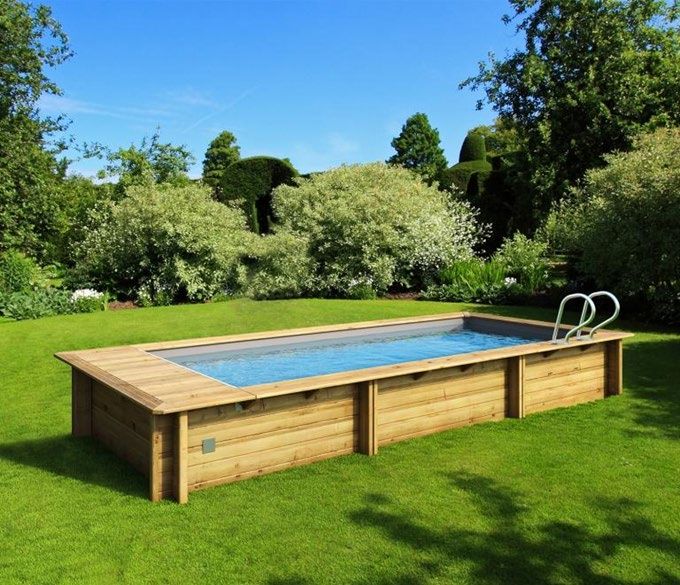
Urban Pool XL
6.50 m x 3.50 m
with integrated
automatic cover

                 INSTALLATION AND
                 OPERATING INTRUCTIONS
                 to be read carefully and kept for future reference

                                                                                                                        GB | PAGE 1

  URBAN POOL BWT myPOOL                                               2019/01 - Indice de révision : C - Code : 37321        1/76
1. PRESENTATION............................................................................................. 6

2. FOREWORD.................................................................................................... 6
    2.1    Storage.....................................................................................................................................6
    2.2    An above-ground kit................................................................................................................6
    2.3    Safety........................................................................................................................................6
    2.4    Assembly..................................................................................................................................7
           2.4.1 Assembly steps.............................................................................................................7
           2.4.2 Tools.............................................................................................................................7
           2.4.3 Assembly time..............................................................................................................7

3. NOMENCLATURE........................................................................................... 8
    3.1    Wood and coping pack............................................................................................................8
    3.2    Accessories pack....................................................................................................................8
           3.2.1 Screws for the pool structure........................................................................................8
           3.2.2 Pool structure metalwork ......................................................................................................10
           3.2.3 Integrated cartridge filtration system...........................................................................10
           3.2.4 Accessories .............................................................................................................................11
    3.3    Automatic cover pack...........................................................................................................11
           3.3.1 Mechanical assembly and automatic cover slat apron...............................................11
           3.3.2 Ladder rails.................................................................................................................11

4. WOOD, A NATURAL MATERIAL................................................................... 12
    4.1    Colour variations...................................................................................................................12
    4.2    Resin beads............................................................................................................................12
    4.3    Salt stains...............................................................................................................................12
    4.4    Greying...................................................................................................................................12
    4.5    Splitting and cracking...........................................................................................................13
    4.6    Knots.......................................................................................................................................13
    4.7    Surface mould........................................................................................................................13
    4.8    Joined wood...........................................................................................................................13
    4.9    Curved wood..........................................................................................................................13

5. EARTHWORKS............................................................................................. 14
    5.1    Introduction............................................................................................................................14
    5.2    Creating the excavation........................................................................................................14
           5.2.1 Material quantities.......................................................................................................14
           5.2.2 Excavation..................................................................................................................14
           5.2.3 Drainage.....................................................................................................................14
           5.2.4 Stone bedding.............................................................................................................16
    5.3    Installing the supporting braces..........................................................................................16
    5.4    Pouring the concrete slab.....................................................................................................19
           5.4.1 Rebar..........................................................................................................................19
           5.4.2 Slab dimensions.........................................................................................................20

6. ASSEMBLING THE WOODEN STRUCTURE ................................................ 21
    6.1    Introduction............................................................................................................................21
    6.2    Application of the bituminous strips...................................................................................23
    6.3    Assembling the slats ............................................................................................................23
    6.4    Mounting the finishing trim on the supporting braces......................................................25
    6.5    Mounting the coping brackets..............................................................................................25
    6.6    Assembling the wooden access ladder...............................................................................26
    6.7    Mounting the metal fittings...................................................................................................27
    6.8    End grain sealer.....................................................................................................................27
    6.9    Finishing trim.........................................................................................................................27

2/76                2019/01 - Indice de révision : C - Code : 37321                                          URBAN POOL BWT myPOOL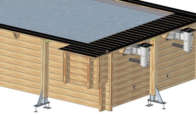
7. INSTALLATION OF THE FILTRATION SYSTEM........................................... 28
    7.1     Filtration group components................................................................................................29
            7.1.1 Rigid module...............................................................................................................29
            7.1.2 Return fitting...............................................................................................................29
            7.1.3 Skimmer......................................................................................................................29
            7.1.4 Filtration group............................................................................................................29
    7.2     Skimmer..................................................................................................................................30
    7.3     Return fitting body.................................................................................................................31
    7.4     Filtration pipework.................................................................................................................31
            7.4.1 Installation of the rigid descending modules...............................................................31
            7.4.2 Assembling the filter...................................................................................................33
            7.4.3 Pump/ filter and manifold module...............................................................................34
            7.4.4 Pipe connections........................................................................................................35

8. PARTS FOR THE AUTOMATIC COVER......................................................... 36
    8.1     Throughwall flange ...............................................................................................................36
    8.2     Bearing mounting unit..........................................................................................................37

9. IN-POOL LADDER........................................................................................ 38
    9.1     Assembling the in-pool ladder.............................................................................................38
    9.2     Drilling holes to mount the ladder.......................................................................................38

10. FITTING THE WATERPROOFING MEMBRANE ........................................... 39
    10.1    Installing the liner locking track...........................................................................................39
    10.2    Drilling for the beam mounting unit.....................................................................................39
    10.3    Applying self-adhesive gaskets...........................................................................................40
    10.4    Fitting the underlay...............................................................................................................40
    10.5    Fitting the liner.......................................................................................................................40
    10.6    Underwater light cable ties...................................................................................................41
    10.7    Filling the pool with water.....................................................................................................41
    10.8    Installing flanges on plastic pool fittings ...........................................................................41
            10.8.1 Return fitting flange.....................................................................................................42
            10.8.2 Throughwall fitting flange............................................................................................42
            10.8.3 Bearing mounting unit flange......................................................................................43
            10.8.4 Skimmer flange...........................................................................................................43
    10.9    Installation of the ladder rails...............................................................................................43

11. ASSEMBLY OF THE AUTOMATIC COVER ................................................... 44
    11.1    Assembly of the automatic cover axle................................................................................44
            11.1.1 Installation of the stainless steel shaft........................................................................44
            11.1.2 Fitting the axle into the bearing mounting unit............................................................44
            11.1.3 Fitting the automatic cover shaft into the axle............................................................44
    11.2    Beam and beam flanges........................................................................................................45
    11.3    Installing the pit wall and the underwater light...................................................................46
    11.4    Automatic cover apron and safety fasteners .....................................................................46
            11.4.1 Advice prior to installation...........................................................................................46
            11.4.2 Assembling the slat cover...........................................................................................47
            11.4.3 Locking the slats in position........................................................................................47
            11.4.4 Installing the cover apron safety fastener...................................................................48
            11.4.5 Securing and releasing the slat cover ........................................................................48
    11.5    Water level in the pool for correct operation of the cover.................................................49

           URBAN POOL BWT myPOOL                                                 2019/01 - Indice de révision : C - Code : 37321                 3/76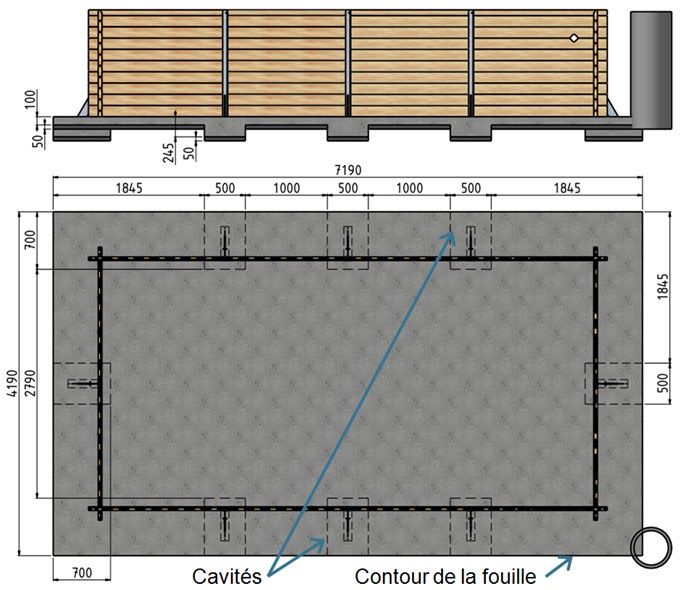
12. INSTALLATION OF THE COPING AND FINISHING ELEMENTS ....................... 50
12.1 Coping ...................................................................................................................................50
12.2 Assembling and installing the duckboarding.....................................................................51
12.3 Ladder hand rail.....................................................................................................................52
12.4 Wiring......................................................................................................................................52
12.5 Automatic cover motor.........................................................................................................53
12.5.1 Safety advice concerning the motor...........................................................................53
12.5.2 Assembly of the automatic cover motor .....................................................................53
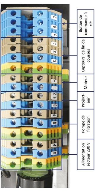
12.6 Electrical panel: mounting and wiring.................................................................................53
12.6.1 Mounting the electrical panel on the wall....................................................................54
12.6.2 Electrical panel power supply.....................................................................................54
12.6.3 Connecting the filtration pump....................................................................................54
12.6.4 Connecting the underwater light.................................................................................54
12.6.5 Connecting the motor ................................................................................................54
12.6.6 Connecting the end of travel sensors.........................................................................55
12.6.7 Connecting the key switch..........................................................................................55
12.7 Adjusting the ends of travel and anti-tear...........................................................................55
13. COVER PIT FOR URBAN POOLS.................................................................. 57
13.1 Nomenclature.........................................................................................................................58
13.1.1 Hardware....................................................................................................................58
13.1.2 Wooden elements.......................................................................................................58
13.2 Cover pit exploded view........................................................................................................59
13.3 Assembly................................................................................................................................60
13.3.1 Assembling the walls..................................................................................................60
13.3.2 Mounting the finishing trim on the ends of the walls...................................................61
13.3.3 Swapping out the pool corner cleat............................................................................61
13.3.4 Fastening the cover pit to the pool..............................................................................61
13.3.5 Fastening the hinges to the cover pit..........................................................................62
13.3.6 Duckboarding assembly.............................................................................................62
13.3.7 Positioning the coping on the cover pit.......................................................................62
13.3.8 Assembling the lock....................................................................................................63
14. SAFETY........................................................................................................ 64
14.1 Electrical supply and filtration pump safety.......................................................................64
14.2 Safety of all users..................................................................................................................64
14.3 Safety of children...................................................................................................................64
14.4 Safety cover...........................................................................................................................65
15. WATER TREATMENT................................................................................... 66
15.1 Water filtration........................................................................................................................66
15.1.1 Using the filter mutli-port valve...................................................................................66
15.1.2 Commissioning the filter.............................................................................................66
15.1.3 Cleaning the pre-filter and the filter.............................................................................66
15.1.4 Length of the filtration cycle........................................................................................67
15.2 Maintaining pool water quality.............................................................................................68
16. MAINTENANCE OF YOUR URBAN POOL.........................................................
69
16.1 Maintenance of the pool structure.......................................................................................69
16.2 Maintenance of the filtration pump......................................................................................69
16.3 Maintenance of the cover......................................................................................................69
16.4 Winterizing the pool...............................................................................................................70
4/76 2019/01 - Indice de révision : C - Code : 37321 URBAN POOL BWT myPOOL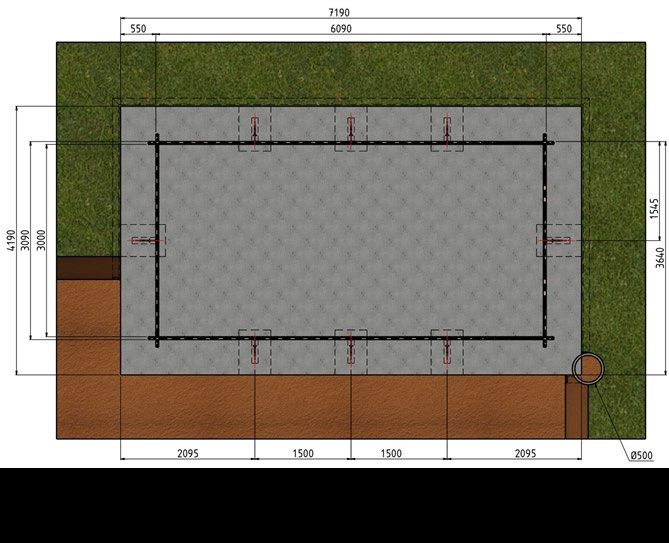
17. GUARANTEE CONDITIONS.......................................................................... 71
   17.1    Guarantee covering the wooden components....................................................................71
   17.2    Guarantee covering accessories.........................................................................................71
           17.2.1 Liner guarantees.........................................................................................................71
           17.2.2 Guarantee covering the sand filtration pump..............................................................72
           17.2.3 Guarantee covering ABS fittings (skimmer, return fitting)...........................................72
   17.3    Guarantee covering the automatic cover............................................................................72
           17.3.1 Guarantee covering the automatic cover mechanical assembly................................72
           17.3.2 Guarantee covering the PVC slats of the cover apron...............................................73

          URBAN POOL BWT myPOOL                                             2019/01 - Indice de révision : C - Code : 37321            5/76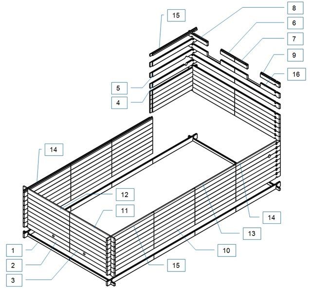
1. PRESENTATION
For your comfort and safety, URBAN pools are fitted with a submerged automatic cover that complies with
the French pool safety standard (NF P90 308), an attribute usually associated with large, top of the range
pools. Housed under the coping the submerged cover keeps the pool water warm and provides discreet
protection for your pool.

2. FOREWORD
Once you have built your pool, keep the documentation (installation instructions, invoice, etc). You will
need these for any future exchanges with our various services.
Great care has gone into the manufacture of your pool, however, some precautions are necessary for its
correct assembly and use. We strongly recommend that you read the installation instructions carefully
before beginning assembly of the pool, and that you keep them for future reference concerning the use
and maintenance of the pool.
In the event of any claim, you will need to quote the pool’s tracking number that you will find at the end of
this document.

2.1    Storage
If you do not intend to assemble your pool immediately, do not unpack the components, store the boxes
in a suitable, well ventilated, cool area protected from the sun and bad weather. The purpose is to avoid
deformation of the wooden elements that would make assembly more difficult.
Deformation of the wood could only be caused by storing the wood other than as recommended. If you had
to unpack your pool, you must repack and restrap the pallet of wooden elements.
Once the wooden elements are unpacked, proceed with assembly within the next 24 to 48 hours. While
storing the boxes, we recommend that you remove the film and insert wooden wedges between each layer
of wood to facilitate the circulation of air.

2.2    An above-ground kit
The kit delivered is for an above-ground installation. If the pool is to be installed in-ground (or partially in-
ground) some extra work and materials will be required:
• acquire the URBAN pool wooden plant housing;
• carry out the necessary excavation work;
• create a drain and a relief well adapted to the terrain around the periphery of the concrete slab;
• cover the in-ground sections of wall with a foundation membrane;
• backfill behind the walls with 10/20 rolled gravel.
The necessary supplies are not included in the kit.

2.3    Safety
Your electrical installation must comply with the standard in effect in the country of installation (C15-100 in
France). Notably, the electrical supply of the pump should be protected by a 30mA residual current device.
Do not hesitate to have this work carried out by a professional to ensure the compliance of your installation.
The kit provided will allow installation of the filtration system 3.5 m from the pool in accordance with the
French safety standard NF C15-100.
Subject to the condition that the cover is mounted according to the installation instructions provided in this
document, the safety cover equipping your Urban pool will secure access to the pool in accordance with
the French safety standard NF P90 308 (December 2013).

6/76              2019/01 - Indice de révision : C - Code : 37321              URBAN POOL BWT myPOOL
Children should only use the pool under the supervision of an adult. This pool is intended for private use only.
Installation of the pool beneath trees is not advised, installation beneath electrical wires is strictly prohibited.

2.4     Assembly
2.4.1 Assembly steps
• excavation
• assemble the supporting braces
• pour the concrete slab
• assemble the wooden structure
• install the filtration system and pool fittings
• assemble the vertical section of the ladder
• lay the waterproofing membrane
• assemble the automatic cover
• install the coping and finishing trim
• wiring
2.4.2 Tools
Excluding the materials required for excavation and pouring the concrete slab, we recommend that you
have the following equipment on hand:
• measuring tools: decameter, rope, big spirit level
• mallet
• drill and drill bits, flat head screw diver, cross head screw driver, drill bit diameter 10 mm
• cutting tools: Stanley knife, metal saw, hole saw diameter 60 mm
• tube or socket wrench (13 and 17mm), set of Allen keys
• finishing tools: sand paper, lime fine
• tools for glueing pipework: medium sand paper, PVC stripper
2.4.3 Assembly time
Excavation and earthworks: 2 DAYS DEPENDING ON THE MATERIALS USED
Supporting braces: ½ DAY (WITH 2 PEOPLE)
Pouring the slab: ½ DAY (WITH TWO PEOPLE) DEPENDING ON THE MATERIALS USED
Wooden structure and cover: 2 DAYS (WITH TWO PEOPLE - THE TIME INDICATED DOES NOT
INCLUDE THE CONCRETE CURING TIME)
Curing of the concrete slab: 21 DAYS (3 WEEKS)

           URBAN POOL BWT myPOOL                               2019/01 - Indice de révision : C - Code : 37321   7/76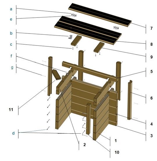
3. NOMENCLATURE
3.1    Wood and coping pack
QTY   DESCRIPTION                      FIGURE             REF        DIMENSIONS (MM)                     TYPE
 4 Wall slat                           Figure 7           n°1          1700 × 78 × 45                    Male
 60 Wall slat                          Figure 7            2          1700 × 145 × 45                Male/female
                                                                                             Male/female, machined to
  2    Wall slat                       Figure 7              3        1700 × 145 × 45
                                                                                              receive the return fitting
                                                                                              Male/female, machined to
  2    Wall slat                       Figure 7             4         1700 × 145 × 45
                                                                                            receive the throughwall flange
                                                                                              Male/female, machined to
  2    Wall slat                       Figure 7              5        1700 × 145 × 45
                                                                                            receive the throughwall flange
                                                                                             Male/female, machined to
  2    Wall slat                       Figure 7           n°16        1700 × 145 × 45
                                                                                                receive the skimmer
  1 Wall slat                         Figure 7             n°6         523 × 137 × 45         Left female for skimmer
  1 Wall slat                         Figure 7             n°8         691 × 137 × 45         Left female for skimmer
  1 Wall slat                         Figure 7             n°7         523 × 137 × 45        Right female for skimmer
  1 Wall slat                         Figure 7             n°9         691 × 137 × 45        Right female for skimmer
 36 Wall slat                         Figure 7            n°10        1570 × 145 × 45                Male/female
  1 Wall slat                         Figure 7            n°11        1700 × 137 × 45                 Female left
  1 Wall slat                         Figure 7            n°12        1700 × 137 × 45               Female right
  4 Wall slat                         Figure 7            n°13         1570 × 70 × 45                   Female
  2 Wall slat                         Figure 7            n°14         1700 × 70 × 45                 Female left
  2 Wall slat                         Figure 7            n°15         1700 × 70 × 45               Female right
 16 Trim                              Figure 7              -         1290 × 137 × 45          For supporting braces
 14 Coping bracket                    Figure 7              -          180 × 150 × 45                 For coping
  1 Ladder rail                       Figure 7              -          1330 × 95 × 35                  For steps
  4 Ladder tread                      Figure 7              -          600 × 145 × 27                  For steps
  8 Coping                            Figure 7              -          1295 × 70 × 45           To finish the corners
  2 Coping                            Figure 50           n°1         1570 × 145 × 28                 Interior left
  2 Coping                            Figure 50           n°2         1570 × 145 × 28                Interior right
  4 Coping                            Figure 50           n°3         1716 × 145 × 28                 Exterior left
  4 Coping                            Figure 50           n°4         1716 × 145 × 28               Exterior right
  1 Coping                            Figure 50           n°5         1621 × 145 × 28                 Interior left
  1 Coping                            Figure 50           n°6         1621 × 145 × 28                Interior right
  8 Coping                            Figure 50           n°7         1500 × 145 × 28           Interior and exterior
  2 Mitered cleat                     Figure 50           n°8           206 × 70 × 28                   Corner
 2 Mitered cleat                      Figure 50           n°9           412 × 70 × 28                   Corner
 10 Straight cleat                    Figure 51             -           585 × 70 × 28            For duckboarding
 20 Duckboarding                      Figure 51             -          600 × 145 × 28                       -
 2 Wall slat                                                -         ≈ 290 × 145 × 45            For martyr block
3.2    Accessories pack
3.2.1 Screws for the pool structure
 QTY       DESCRIPTION          KIT                                               PURPOSE
      Torx safety screw 6 × 30,
   3                             Y                       Fasten the elastic strap underneath the duckboarding
      A2 SS
      Hex screw M8 × 120, A2                             Fasten the beam and counter plate to the polyamide blocks
   4                             Y
      SS, DIN 931                                        from outside the pool
      Screw, M8 × 70 DIN 603 A4
   4                             Y                       Fasten the beam and counter plate from inside the pool
      (round head, square neck)
      Countersunk screws, 4.2
   4                             Y                       Fasten the polyamide blocks to the pit wall flanges
      × 19, A4 SS, DIN 7982

8/76               2019/01 - Indice de révision : C - Code : 37321                       URBAN POOL BWT myPOOL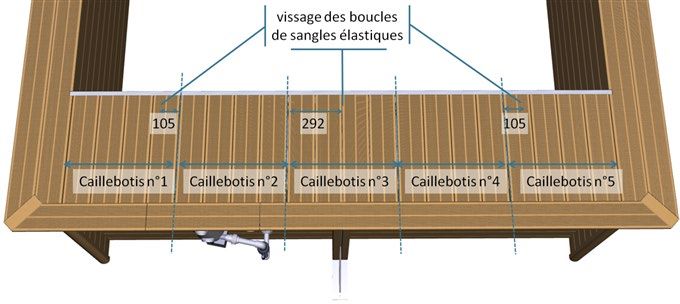
Stove screws, M8 × 16,             Fasten the elastic strap at the bottom of the pit wall modules (x 3)
 7                                  Y
      A4 SS torx                         Fasten the pit wall to the beam mounting plate (× 4)
      Hex screws, M8 × 20, A4
 8                                  Y    Assembly of the pit wall modules
      SS,
                                         Fasten the pit wall brackets to the beam mounting plates (4 nuts
                                         & 4 washers)
                                         Fasten the beam and counterplate from inside the pool (4 nuts &
                                         4 washers)
23    Nut M8, A4 SS                 Y
                                         Assembly of the pit wall modules (16 nuts & 16 washers)
                                         Fasten straps to the pit wall (3 nuts & 3 washers)
                                        Fasten the pit wall to the beam mounting plate (4 nuts & 8
                                        washers)
                                         Fasten the pit wall brackets to the beam mounting plates (4 nuts
                                         & 4 washers)
                                         Fasten the beam and counterplate from inside the pool (4 nuts &
                                         4 washers)
35    Washer M8, A4 SS              Y
                                         Assembly of the pit wall modules (16 nuts & 16 washers)
                                         Fasten straps to the pit wall (3 nuts & 3 washers)
                                        Fasten the pit wall to the beam mounting plate (4 nuts & 8
                                        washers)
56  Nut, M10, zinc plated steel     A    Fasten the 3 jacks to each of the four supporting braces
 8  Nut, M8, A4 SS, DIN 934         B
8   Washer M8 SS A4                 B
                                         Fasten the ladder hand rail to the coping
    Mushroom head screw,
 8                                  B
    M8x50, A2 SS
    Countersunk screw, 5 ×
160 40 A4 SS, torx, threaded        C    Lock the slats together at the supporting braces
    over 25 mm
    Torx safety screw 6 × 30,            Fasten the wall slats to the supporting braces from outside
 80                                 D
    A2 SS                                the pool
    Torx safety screw 6 × 20,
416                                 G    Fasten the coping modules to the coping brackets
    A2 SS
    Countersunk screw, 4×35
100 A4 SS, torx, threaded           H    Mount the Hung track under the coping
    over 20 mm
    Domed head nail, 2.8 × 60,
24                                  I    Fasten the finishing trim to the walls (3 nails per profile)
    A2 SS
    Countersunk screw 5 × 60
                                         Assembly of the wooden steps: fasten the 4 treads
16 zinc plated torx threaded over   K
                                         to the 2 rails
    35 mm
    Countersunk screw 4 × 25
  4                                 K    Mount the warning panel
    zinc plated torx
    Countersunk screw 5 × 100,
                                         Mount the wooden coping brackets on the walls
 28 A4 SS, torx, threaded over      L
                                         (2 × 14 consoles)
    60 mm
    Countersunk screw 5 × 80,
 48 A4 SS, torx, threaded over      L   Fasten the trim over the supporting braces
    50 mm

        URBAN POOL BWT myPOOL                              2019/01 - Indice de révision : C - Code : 37321      9/76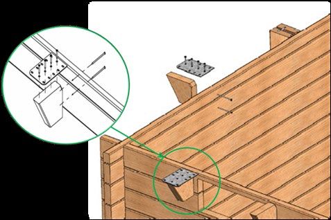
Countersunk screw 5 ×
                                                      Fasten the metallic plates to the wooden coping brackets
  56    40, A4 SS, torx, threaded              M
                                                      (4 x 14)
        over 25 mm
        H head screw M8x25 zinc
  16                                           M      Mount the skimmer bracket
        plated steel
  16    M8 nut zinc plated steel               X
        Countersunk          screw                    Mount the upper connecting plates
  16                                           X
        5.5x25 SS A4 torx
        Countersunk screw 5 ×
  80    40 SS A4 torx threaded                 Z      Assembly of the duckboarding (4 x 13 duckboarding)
        over 25 mm
  1     Torx bits                              J      T20 ; T25 ; T30
  1     Wood drill bits 4 × 75 mm              J      Pre-drill the liner locking rail (hung)

3.2.2 Pool structure metalwork
 QTY                                                    DESCRIPTION
                      Coping module fittings (× 12 right, × 12 left)
      Steel mounting
   1                  Corner coping module fittings (× 4)
      elements kit:
                      Jacks for the supporting braces (× 12 back, × 8 front)
                      Beam mounting unit counter plate(× 2)
                      Hand rail bracket (× 1 right, × 1 left)
   1 Metalwork kit:   Skimmer blocking bracket (× 2)
                      Pit wall bracket (× 2)
                      Pit wall flange (× 2)
                      Metallic plates to fasten the coping modules (only 14 of the 17 plates will be
  14
                      used)
   8                  Steel support braces

3.2.3 Integrated cartridge filtration system
 QTY                                                       DESCRIPTION
                           2 skimmer suction modules
                           Suction manifold 2 inlets
                           Filtration pump P-AP 8m3/h, 1ph
                           Pump base
                           Sand filter P-FS 500 EH
      Filtration pump and
   1                       Filter base
      unions
                           Three 25kg of sand
                           Isolation module for P-FS filter
                           Y module for return fittings
                           2 return fitting modules
                           21 m of grey pipes D45
                           2 complete skimmers (body, flange and trim, seals, set of screws, weir)
   1 Pack of pool fittings
                           2 complete return fittings (body, flange, eyeball and trim, seals, set of screws)

10/76             2019/01 - Indice de révision : C - Code : 37321                          URBAN POOL BWT myPOOL
3.2.4 Accessories
QTY DESCRIPTION
1 Installation instructions
1 Warning panel to mount on the pool wall
1 Bitumous strips to provide insulation between the pool walls and the concrete slab
2 Roll of black plasticised PVC to protect the liner against screw heads
1 Underlay
1 Grey liner
16 1.18 m length of PVC liner locking track
2 SS hand rails
3.3 Automatic cover pack
3.3.1 Mechanical assembly and automatic cover slat apron
QTY DESCRIPTION
Anodised aluminium axle, Ø150, length 2790 mm, with two stands, a bearing and three supports
1
to attach the slat apron
1 SS motor shaft, 309 mm, for the throughwall flange with plastic locking pin and screw
1 Throughwall flange (body, gaskets, flange and screws)
1 Bearing (body, gaskets, flange and screws)
Automatic cover apron (49 slats) fitted with three connection straps on the axle side and two safety
1
fastening straps
2 Automatic cover safety fastener
Electrical panel with control pad for the automatic cover, key switch, filtration timer and water
1
slinger (o-ring) for the SS motor shaft,309 mm, inserted in the throughwall flange
1 Urban pool reduction geared motor with pins (pin for SS shaft and U shaped pin)
Lacquered aluminium beam 60 x 87 x 1988 mm with gaskets (4 washers and 4 plates) and 2
1
polyamide blocks
3 Pit wall module
1 LED underwater light
3 Black elastic strap to hold the automatic cover apron
3.3.2 Ladder rails
QTY DESCRIPTION
2 Aluminium rails ,Ø40, and ball joints
3 ABS treads with aluminium screws
2 Support, shell and adhesive gaskets with SS screws
2 Bumpers to protect the liner
URBAN POOL BWT myPOOL 2019/01 - Indice de révision : C - Code : 37321 11/764. WOOD, A NATURAL MATERIAL Being a natural material, wood will have some imperfections. These are normal and have no impact on the service life of the product. A certain number are superficial and do not fall within the scope of the guarantees. 4.1 Colour variations Colour variations are common to every species of wood. Treatment brings them out because the depth of penetration of the product depends on the wood density and grain. Weathering of wood outdoors will significantly attenuate these colour variations. 4.2 Resin beads When resinous wood species are autoclaved, the alternating pressure and vacuum can cause sticky residue to rise to the surface. To remove it, scrape it carefully with an appropriate tool, being careful not to touch the wood. Turpentine spirits could also be effective, but could stain the wood if too much is applied. 4.3 Salt stains Small green stains are frequently found on the surface of autoclaved wood. These can be removed with light sanding. If left untreated, this colour will disappear over time. 4.4 Greying Wood exposed to the sun and the moon is susceptible to greying. Some of the wood could already be greyed due to the storage conditions of the various elements of the structure. This is a natural phenomenon that has no impact on the structural integrity of the product. The colour of the whole structure will even out after a few months of exposure.. 12/76 2019/01 - Indice de révision : C - Code : 37321 URBAN POOL BWT myPOOL
4.5    Splitting and cracking
Wood expands and contracts when exposed to variations in
humidity and temperature. As it dries, wood contracts unevenly
resulting in the appearance of cracks. While these can seem to
be cause for concern, they have no impact on the mechanical
properties of the product and therefore do not fall within the
scope of the guarantee.

4.6    Knots
Knots mark the places where branches were attached. The
quantity and size depends on the species of wood and the
sorting process. For outdoor installations, small adherent knots
are acceptable.

4.7    Surface mould
Mould, caused by microscopic fungi, can grow on wood,
particularly on resinous species, on which the growth can
appear as “blueing”. It is a surface phenomenon, exacerbated
by heat, humidity and inadequate aeration and is characterised
by stains ranging from light to dark blue. They can be removed
by wiping the surface.
Remember that class IV treated wood is protected against
attack by fungi that could destroy the physical and mechanical
properties of the wood
.

4.8    Joined wood
To ensure the highest quality in the selection of our wood, it
is sorted meticulously before planing. Sections that features
defects on both sides are removed and the wood is then joined
together (see image).
This is no way penalises the mechanical properties of the wood.

4.9    Curved wood
Due to the constant pressure exerted by the water, the walls of the pool may curve slightly over time.
This phenomenon, attributable to the natural elasticity of wood, will stabilise of its own accord and in no
way would lead to failure of the wooden slats.
It is not a defect, and would not constitute grounds for a guarantee claim.

          URBAN POOL BWT myPOOL                            2019/01 - Indice de révision : C - Code : 37321   13/76
5. EARTHWORKS
5.1 Introduction
After determining the ideal position for your pool (preferably, orient the pool so that skimmers face into
dominant winds), start with the excavation required to accommodate the concrete slab that will seal in the
support braces and form the base of your pool. Seek the assistance of a professional if required.
Never backfill under the pool to achieve a level surface, the layer of stone bedding and the slab must be
seated on stable ground.
In this section on earthworks, information provided takes into account the plant housing and the drainage
system required for an in-ground or partially in-ground installation. For an above-ground installation, the
plant housing and drainage system are not required. The excavation and the slab will be rectangles,
7190 mm long and 4190 mm wide.
5.2 Creating the excavation
5.2.1 Material quantities
The quantities of materials required are shown in the table below
Estimated volume of stone bedding 3,7 m3 20/40 gravel
Geotextile surface area (pool floor) 31,6 m² nonwoven felt
Polyane surface area 31,6 m² polyethylene sheet
Theoretical length of the Ø80 mm drain 31,6 m PVC
Rebar 34 m ST25C rebar
Slab, 15 cm thick 5,2 m3 C25/30 concrete
Protective membrane for in-ground walls (rolls 1.5 m high) 33 ml polyethylene
Backfill 20 m3 10/20 rolled gravel
5.2.2 Excavation
Dig out an area, the length and the width of which should correspond to the length and width of the inner
walls of the pool increased by 0.55 m around the entire periphery of the pool, that is, 7.1 4.1 m for a pool
without a plant housing.
For an above-ground installation, so that the slab is flush with the ground, excavate to a depth of
0.26 m. For partially in-ground installations, the depth of the hole is determined by the installer.
For example, to sink the pool 1 m into the ground (leaving 33 cm above ground), the hole should be
1.26 cm deep.
To install the pool fully in-ground (bottom of the coping flush with the ground), the hole should be 1.56 m
deep.
Take care, this measurement my be greater if the moisture content of the wood is high when the pool
is installed (wood stored in a humid or poorly ventilated area).
5.2.3 Drainage
In the case of an in-ground installation, create a drain around the entire outer periphery of the pool. The
drain, which should have a diameter of 80 cm, should be connected to a relief well located in one of the
corners on the outside edge of the excavation. The relief well should be 0.5 m deeper than the floor of the
excavation and should have a diameter of at least 0.3 m to accommodate a lift pump.
14/76 2019/01 - Indice de révision : C - Code : 37321 URBAN POOL BWT myPOOLperipheral Ø80 drain
peripheral
drain
Root barrier Wooden
or felt frame
Drainage
gravel
Undisturbed
earth
Concrete slab
Min depth 150 mm
Waterproofing film
Stone bedding
Geotextile felt
Relief well, 500 mm deeper than the floor of the excavation (outlet of
the peripheral Ø80 drain)
Figure 1 – Drainage system installation diagram
URBAN POOL BWT myPOOL 2019/01 - Indice de révision : C - Code : 37321 15/765.2.4 Stone bedding
Level the floor of the excavation as much as possible, and then roll out the geotextile to cover the entire floor.
Using 20/40 mm gravel lay hardcore to a depth of 110 mm around the entire periphery of the excavation.
Correct tamping of the gravel will ensure a neat finish of the excavation floor, and facilitate installation of
the supporting braces.
Remove the gravel at the positions shown in Figure 2 in order to create four 500 × 650 mm recess
90 mm deep (as measured from the surface of the stone bedding). The recesses will accommodate the
steel braces, once imprisoned in the concrete, these braces will support the pool structure.
Recesses Contour of the excavation
Figure 2 – Positions of the recesses created to accommodate the supporting braces
5.3 Installing the supporting braces
The reinforcing metallic structure is comprised of metal posts joined together at the top and the bottom with
flat bars (Figure 3 ). Note how the parts overlap to allow correct positioning of the structure The flat bars at
the top will be removed once the concrete slab has been poured.
16/76 2019/01 - Indice de révision : C - Code : 37321 URBAN POOL BWT myPOOLa)
Depending on the version, the
flat bars are delivered in two
sections to be bolted together
b)
Figure 3 – a and b – Assembling the flat bars on the support braces
Install the supporting braces in each of the eight locations, having first fitted the recesses with jacks
(Figure 3 and Figure 4). Use 8 double acting jacks,12 single acting jacks and 56 screws with a diameter of
10 mm (bag A). The top screws should be inserted after the height of the bottom screws has been adjusted.
These posts are joined together at the bottom with 12 flat bars (B) 1.6 m long bolted together at 2 points.
The distance between each post is determined by these flat bars: it should be 1.5 m. They are joined
together at the top by 4 flat bars (B) 1.6 m long (identical to the flat bars at the bottom of the structure) and
4 flat bars (C) that are 2.253 m long in the corners (screw in bag A, see Figure 5 ).
At each end of the flat bars there are four holes. At the bottom, the outer holes (Figure 5) should be used
to fix them in position, while the inner holes should be used at the top of the structure (Figure 3).
URBAN POOL BWT myPOOL 2019/01 - Indice de révision : C - Code : 37321 17/76Adjusted using jacks Top of the pool wall (under the coping)
Figure 4 – Position of the support braces and top and bottom connecting bars
18/76 2019/01 - Indice de révision : C - Code : 37321 URBAN POOL BWT myPOOLFigure 5 – Installation of the jacks under the supporting braces
The supporting braces must under no circumstances extend above the top of the pool wall (just
beneath the coping) after adjustment of the supporting brace jacks. On the contrary, it is not problematic
if the top of the supporting braces are 1 or 2 cm below the top of the pool wall.
After assembly, adjust the supporting braces and check carefully that they are correctly positioned: plumb,
level, correct alignment of the supporting braces. To ensure that the supporting braces stay in place after
adjustment, you can pre-seal them with a small amount of concrete.
TIP: You can use the supporting braces to visualise how high the concrete slab should be once it has
been poured. To do this, taking the top of the pool wall, below the coping, as level 0 measure 1.303 m
and mark this distance on the front of the supporting brace. This mark will correspond to the height of the
finished concrete slab.
The height of the pool under the coping may be over 1.303 m if the moisture content of the wood is
high at the time of installation of the pool (wood stored in a humid or poorly ventilated area).
Take particular care while carrying out these assembly steps, they will determine the quality of the
pool finish. Incorrect positioning of the supporting braces may render assembly of the pool walls
impossible.
Check that all the dimensions quoted in Figure 4 are correct before proceeding with the next step.
5.4 Pouring the concrete slab
5.4.1 Rebar
Before pouring the concrete, lay the top layer of welded rebar mesh (type ST25C) over the floor of the
excavation (the mesh should be set back 3 to 5 cm from the edge around the entire periphery). Some
cutting around the supporting braces will be necessary. The mesh should overlap by one and a half
squares and should be connected together using metal ties. The mesh should be raised using spacers to
ensure that will sit in the centre of the slab. If you are using self-levelling concrete, you should place a layer
of polyethylene sheeting under the rebar mesh because the concrete is very liquid and could flow into the
spaces between the gravel. Use C25/30 grade concrete as a minimum.
URBAN POOL BWT myPOOL 2019/01 - Indice de révision : C - Code : 37321 19/765.4.2 Slab dimensions
The characteristics of the concrete slab are provided in Figure 6. The dimensions of the slab are such the
feet of the wooden pool access ladder will not rest on the slab. However, we recommend that the feet of
the ladder rest on a solid surface (cement blocks or slab for example).
Supporting
brace
Concrete slab
Stone bedding
Figure 6 – Characteristics of the concrete slab
While pouring the slab over the floor of the excavation, make sure that the upper rebar mesh is properly
encased in the concrete: the layer of concrete above the mesh must be at least 3 cm thick.
Refer to Figure 6 to determine the depth of the slab to be poured: it should be 150 mm thick, and of a
height to ensure that the distance between the surface of the slab and the top of the excavation is 1303
mm if the pool is to be installed in-ground.
Level and smooth the slab carefully to void surface defects that will have to be corrected later.
The slab provides seating for the wooden structure. Any levelling defects will become apparent when
the pool is filled with water. Similarly, significant surface defects will detract from the quality of the
finish of the pool floor.
20/76 2019/01 - Indice de révision : C - Code : 37321 URBAN POOL BWT myPOOL6. ASSEMBLING THE WOODEN STRUCTURE
6.1 Introduction
You may begin assembly of the pool walls 2 to 3 days after the slab is poured without waiting for the
concrete to cure completely. However, you must wait at least 3 weeks for the concrete to cure before filling
the pool with water.
Before starting to assemble the wooden walls, make sure that the slab is free from any defects and that it
is perfectly level. The finish of the concrete slab will determine the correct seating of the walls, the quality
of the pool floor and the finish of the pool. A level defect will be accentuated and visible when tee pool is
filled with water. It could also make it impossible to assemble the pool walls. If necessary, correct defects
by sanding or resurfacing the slab.
Your pool is comprised of several slat references, the positions of the slats are illustrated on various diagrams
(Figure 7).There are specific slats to house the pool fittings (skimmer, return fitting, beam mounting unit
and throughwall flange required to mount the automatic cover axle). Assembly of this structure is described
step by step in this section.
URBAN POOL BWT myPOOL 2019/01 - Indice de révision : C - Code : 37321 21/76NUMBER QUANTITY DIMENSIONS TYPE SPECIFIC
(MM)
1 4 1700 x 78 x 45 male slat
2 60 1700 x 145 x 45 male/ female slat
3 2 1700 x 145 x 45 male/ female slat return fitting
4 2 1700 x 145 x 45 male/ female slat throughwall flange
5 2 1700 x 145 x 45 male/ female slat throughwall flange
6 1 523 x 145 x 45 male/ female slat left skimmer
7 1 523 x 145 x 45 male/ female slat right skimmer
8 1 691 x 145 x 45 male/ female slat left skimmer
9 1 691 x 145 x 45 male/ female slat right skimmer
10 36 1570 x 145 x 45 male/ female slat
11 1 1700 x 137 x 45 female slat left
12 1 1700 x 137 x 45 female slat right
13 4 1570 x 70 x 45 female slat
14 2 1700 x 70 x 45 female slat left
15 2 1700 x 70 x 45 female slat right
16 2 1700 x 145 x 45 male/ female slat skimmer
Figure 7 – Exploded view of the wooden structure
22/76 2019/01 - Indice de révision : C - Code : 37321 URBAN POOL BWT myPOOL6.2 Application of the bituminous strips
Start by unrolling the bituminous strip that will insulate the wooden structure from the concrete slab (Figure 8
Figure 8 – Laying the bituminous strips
6.3 Assembling the slats
Lay out the ½ slats that constitute the pool widths, then, in the corners, slot in the slats that constitute the
pool lengths. After laying out the first row of slats, make sure that the diagonals are equal.
Fit the slats together, according to the assembly diagram shown in Figure 9 and taking care to position the
machined slats correctly (see Figure 7). The tongues should always be oriented upwards, and the grooves
downwards.
female half-slat
(70 x 45)
female slat
(137 x 45)
male/ female slat
(145 x 45)
female half-slat
(78 x 45)
Figure 9 – Slotting together the wooden slats
While assembling the pool walls, make sure as of the first rows that the slats are fully engaged in the
grooves.
After assembling the first row, check that the slats are perfectly level, screw together the slats constituting
the pool lengths:
• referring to Figure 10, screw the slats together using 2 screws per pair of slats in each of the
10 rows, that is, 160 countersunk screws 5 × 40 A4 SS torx threaded over 25 mm (bag C);
• fix them to the 8 supporting braces (these are pre-drilled as shown in Figure 11) using 72 torx safety
screws 6 × 30 A2 SS (bag D).
URBAN POOL BWT myPOOL 2019/01 - Indice de révision : C - Code : 37321 23/76Figure 10 – Screwing the slats together
Figure 11 – Fastening the slats to the supporting braces
For correct assembly, it may be necessary to use a mallet and clamp to remedy light slat deformations
caused by storage. Do not strike the wooden slats directly, use the protective martyr blocks.
The heads of screws inserted from the inside of the pool should be flush with the pool wall to avoid
damaging the liner.
The height under the coping of the assembled pool will only be 1.303 m if the moisture content of the
wood is normal and the slats are properly fitted together.
Remove any splinters raised by the screws as you go.
24/76 2019/01 - Indice de révision : C - Code : 37321 URBAN POOL BWT myPOOL6.4 Mounting the finishing trim on the supporting braces
Put the supporting brace finishing trims in position. They should be flush with the top of the pool wall.
Working from the inside of the pool, insert screws as shown in Figure 12 using 3 countersunk screws
5 × 80 A4 SS torx, threaded over 50mm (bag L) per half trim, that is a total of 48 screws. The 2 half trims
do not meet, the metallic brace will remain visible.
Should it be necessary to resize the trims (for example, if the pool is installed partially in-ground) orient the
cut surface upwards so that the cut side is not in contact with the ground.
Figure 12 – Mounting the supporting brace finishing trim
6.5 Mounting the coping brackets
Fasten a metallic mounting plate to each of the 14 wooden brackets using 4 countersunk zinc plated
screws 5 x 40, torx, threaded over 25 mm (bag M), that is a total of 56 screws, as shown in Figure 13:
the edge of the width of the metal plate should be aligned with the vertical surface of the bracket that is in
contact with the pool wall.
Referring to the diagram provided in Figure 14 fasten the wooden brackets, furnished with metallic
mounting plates, to the pool wall using two screws per bracket, that is a total of 28 countersunk screws,
5 x100 A2 SS, torx, threaded over 60 mm (bag L). The metallic mounting plates should be facing upwards.
In any case, the metallic mounting plates should be flush with the top of the pool wall. Check that the plates
are level to allow subsequent mounting of the coping.
Figure 13 – Fastening metallic plates to the wooden brackets
URBAN POOL BWT myPOOL 2019/01 - Indice de révision : C - Code : 37321 25/76Figure 14 – Coping mounting bracket positions 6.6 Assembling the wooden access ladder Assemble the ladder according to Figure 15 using16 zinc plated countersunk screws 5 × 60, torx, threaded over 35 mm (bag K), and fasten the handrail brackets to the right and left hand side of the ladder using 8 SS torx safety screws, 6 x 20 (bag G). Next, with 8 safety screws 6 x 20, A2 SS (bag G), use the left- and right-hand handrail brackets to fasten the ladder to the pool wall as shown in Figure 16. Figure 15 – Assembling the wooden access ladder Figure 16 – Fastening the access ladder to the pool wall For you own comfort, we recommend that you mount the ladder on the wall opposite the skimmer. In any case, do not locate the ladder within the third of the pool that contains the automatic cover axle. The ladder must be located at least 30 cm from the corners of pool. Remember that wooden access ladder and in-pool ladder should face each other. 26/76 2019/01 - Indice de révision : C - Code : 37321 URBAN POOL BWT myPOOL
6.7        Mounting the metal fittings
The metal fittings are intended to support the coping and allow them to be fixed in position. Make sure that
they are correctly positioned. They should be flush with the top of the pool wall and aligned with each other
and the coping bracket plates.
• On top of each of the 8 metallic supporting braces and the two wooden supporting braces, place a ‘right-
    hand’ fitting and a ‘left-hand’ fitting from the ‘Fastening elements’ kit as shown in Figure 17. Use 6 safety
    screws 6 × 20 in A2 SS (bag G) per fitting, that is a total of 96 screws.
• In each of the corners,mount a right-hand fitting, a left-hand and a corner fitting as shown in Figure 18.
    Use 4 safety screws 6 × 20, A2 SS (bag G) per corner fitting 6 safety screws 6 × 20 in A2 SS (bag G)
    per fitting, that is a total of 64 screws.

Figure 17 – Mounting the fittings on top of the supporting brace   Figure 18 – Mounting the fitting in the corners

6.8        End grain sealer
Using a brush, paint the ends of the slats in each corner with an end grain sealer to limit deformation over
time.
This product is white on application, but becomes colourless when dry. Drying time is 2 to 3 hours. If the
temperature is high or the drying time is too fast, apply a second coat. Follow the safety instructions on the
container. Rinse the brush after use.
6.9        Finishing trim
Use 3 domed head nails, 2.8 x 60 A2 SS (bag l) to fasten the wooden finishing trim to the edge of each
wall. The nails should be evenly spaced and the finishing trim should be pre-drilled using a drill bit with a
diameter of 4mm. (Figure 19).
Apply an adhesive strip (roll provided) to the
vertical joins on the inner walls of the pool taking
care to ensure that the screw heads are covered
(Figure 20). This will protect the liner from the screw
heads that could damage it.

                                                                        Figure 19 – Wooden trim               Figure 20 – Protective adhesive
                                                                                                                           strip

               URBAN POOL BWT myPOOL                                       2019/01 - Indice de révision : C - Code : 37321               27/76
7. INSTALLATION OF THE FILTRATION SYSTEM
The pump’s electrical supply must be protected by a 30mA upstream from the installation.
The filtration system as supplied in the kit, along with all other electrical devices, should be wired in in
accordance with the standards in effect in the country of installation.
Do not hesitate to seek the assistance of a professional to ensure the compliance of your installation.
The filter should be installed at a height below the water level. At a height above the water level, there
is a risk of deformation due to de-pressurisation. The maximum acceptable height is the level of the
coping. If the filter is installed above the water level, a check valve must be mounted on the return
fittings and an easily accessible check-valve should also be installed on the suction line (these items
are available from pool suppliers).
Figure 21 – Proposed position of the filtration group
The installation described is a sample installation, the kit provided allows for installation of the filtration
group at a distance of 3.5 m from the pool in accordance with standards in effect. It may be necessary
to adjust the pipe lengths depending on the configuration of the installation site, the type of installation
(above-ground, partially in-ground, in-ground), the type of plant housing and other restrictions imposed
by the installation.
Refer to the instructions for mounting the sand filter provided below, and the pump’s operating
instructions. Note the sketch of the filtration system that shows all the various components and
connection information.
FLOWRATE, NO VOLUME
DIRECTIONAL FILTERED
FILTRATION
DESCRIPTION JET ON THE FILTER DIAMETER SAND
SURFACE AREA IN 24 HOURS
RETURN
FITTINGS
URBAINE 6.5
6 m3/h 500 mm 3 × 25 kg 0;2 m² 232.8 m3
× 3.5
28/76 2019/01 - Indice de révision : C - Code : 37321 URBAN POOL BWT myPOOLYou can also read