V20 User Guide ENGLISH - Error
←
→
Page content transcription
If your browser does not render page correctly, please read the page content below
V20
User Guide
ENGLISH

             bandg.com
Preface
Disclaimer
As Navico is continuously improving this product, we retain the
right to make changes to the product at any time which may not
be reflected in this version of the manual. Please contact your
nearestdistributor if you require any further assistance.
It is the owner’s sole responsibility to install and use the equipment
in a manner that will not cause accidents, personal injury or
property damage. The user of this product is solely responsible for
observing safe boating practices.
NAVICO HOLDING AS AND ITS SUBSIDIARIES, BRANCHES AND
AFFILIATES DISCLAIM ALL LIABILITY FOR ANY USE OF THIS PRODUCT
IN A WAY THAT MAY CAUSE ACCIDENTS, DAMAGE OR THAT MAY
VIOLATE THE LAW.
Governing Language: This statement, any instruction manuals,
user guides and other information relating to the product
(Documentation) may be translated to, or has been translated from,
another language (Translation). In the event of any conflict between
any Translation of the Documentation, the English language
version of the Documentation will be the official version of the
Documentation.
This manual represents the product as at the time of printing.
Navico Holding AS and its subsidiaries, branches and affiliates
reserve the right to make changes to specifications without notice.
Copyright
Copyright © 2017 Navico Holding AS.
Warranty
The warranty card is supplied as a separate document.
In case of any queries, refer to the brand website of your unit or
system: www.bandg.com
RF Emissions notice
This equipment complies with FCC radiation exposure limits set
forth for an uncontrolled environment. This device’s antenna must
be installed in accordance with provided instructions; and it must
be operated with minimum 1.8 m spacing between the antennas
and all person’s body (excluding extremities of hands, wrist and feet)
2| | V20 operator manualduring operation. Further, this transmitter must not be co-located or
operated in conjunction with any other antenna or transmitter.
FCC Statement
This device complies with Part 15 of the FCC Rules. Operation
is subject to the following two conditions: (1) this device may
not cause harmful interference, and (2) this device must accept
any interference received, including interference that may cause
undesired operation.
¼¼ Note: This equipment has been tested and found to comply with
the limits for a Class B digital device, pursuant to Part 15 of the FCC
Rules. These limits are designed to provide reasonable protection
against harmful interference in a normal installation. This equipment
generates, uses and can radiate radio frequency energy and, if not
installed and used in accordance with the instructions, may cause
harmful interference to radio communications. However, there is no
guarantee that interference will not occur in a particular installation.
If this equipment does cause harmful interference to radio or televi-
sion reception, which can be determined by turning the equipment
off and on, the user is encouraged to try to correct the interference
by one or more of the following measures:
Reorient or relocate the receiving antenna.
Increase the separation between the equipment and receiver.
Connect the equipment into an output on a circuit different
from that to which the receiver is connected.
Consult the dealer or an experienced technician for help.
A shielded cable must be used when connecting a peripheral to
the serial ports.
Innovation, Science and Economic
Development Canada Compliance
This equipment complies with ISEDC RF radiation exposure limits
set forth for an uncontrolled environment. This transmitter must not
be co-located or operating in conjunction with any other antenna
or transmitter. This equipment should be installed and operated
with minimum distance 1.8m between the radiator & your body.
ISEDC exposition aux radiations:
Cet équipement est conforme avec ISEDC les limites d’exposition
aux rayonnements définies pour un contrôlé environnement.
Cet émetteur ne doit pas être co-localisés ou fonctionner en
| V20 operator manual |3conjonction avec une autre antenne ou émetteur.
Cet équipement doit être installé et utilisé avec un minimum de 1.8
m de distance entre le radiateur et votre corps.
CE Compliance Statement
This product complies with CE under directive 2014/53/EU. The
relevant Declaration of Conformity is available in the following
website under model documentation section:
www.bandg.com
Warning
The user is cautioned that any changes or modifications not
expressly approved by the party responsible for compliance could
void the user’s authority to operate the equipment. This equipment
generates, uses and can radiate radio frequency energy and, if not
installed and used in accordance with the instructions, may cause
harmful interference to radio communications. However, there is
no guarantee that the interference will not occur in a particular
installation. If this equipment does cause harmful interference to
radio or television reception, which can be determined by turning
the equipment off and on, the user is encouraged to try to correct
the interference by one or more of the following measures:
• Reorient or relocate the receiving antenna
• Increase the separation between the equipment and receiver
• Connect the equipment into an outlet on a circuit different from
that of the receiver
• Consult the dealer or an experienced technician for help
4| | V20 operator manualCountries of intended use in the EU
AT - Austria HU - Hungary PL - Poland
BE - Belgium IS - Iceland PT - Portugal
BG - Bulgaria IE - Ireland RO - Romania
CY - Cyprus IT - Italy SK - Slovak Republic
CZ - Czech Republic LV - Latvia SI - Slovenia
DK - Denmark LI - Liechtenstein ES - Spain
EE - Estonia LT - Lithuania SE - Sweden
FI - Finland LU - Luxembourg CH - Switzerland
FR - France MT - Malta TR - Turkey
DE - Germany NL - Netherlands UK - United Kingdom
GR - Greece NO - Norway
Trademarks
B&G® and Navico® are registered trademarks of Navico.
NMEA® and NMEA 2000® are registered trademarks of the National
Marine Electronics Association.
Navico recommends that you check the radio operating licensing
requirements of your country before using this VHF radio. The
operator is solely responsible for observing proper radio installation
and usage practices.
Notes on MMSI and DSC
The user MMSI (Marine Mobile Service Identity) is a unique nine
digit number. It is used on marine transceivers that are capable of
using DSC (Digital Selective Calling). Digital Selective Calling offers
significant safety and convenience advantages over older VHF radios
without this functionality.
¼¼ Note: many countries do not have radio repeaters that support DSC
message relaying. However DSC can still be useful for direct ship-to-
ship communication, where the other vessel is also equiped with a
DSC capable radio.
You must obtain a user MMSI and enter it into your radio in order to
use the DSC functions. Contact the appropriate authorities in your
country to obtain an MMSI number - charges may apply. If you are
unsure who to contact, consult your B&G dealer.
| V20 operator manual |5¼¼ Note: DSC distress calls generated by this radio are limited to the
same range restrictions that apply to regular VHF transmissions. The
vessel sending a distress can only rely upon DSC if within range of a
GMDSS Coast Radio Station. Typical VHF range may be about 20NM,
though this varies greatly depending upon installation, antenna
type, meteorological conditions, etc.
About this manual
This manual is a reference guide for installing and operating a V20
VHF radio. Important text that requires special attention from the
reader is emphasized as follows:
¼¼ Note: Used to draw the reader’s attention to a comment or some
important information.
! Warning: Used when it is necessary to warn personnel that
they should proceed carefully to prevent risk of injury and/or
damage to equipment/personnel.
6| | V20 operator manualContents 8 General Information 9 How to display and navigate menus 12 Key functions 15 The radio menus 15 Scan menu 16 Watch 17 Display 18 Radio setup 20 DSC setup 23 Alarms 24 Reset 25 DSC call menu 25 DSC calls 27 Track buddy 28 Contacts 30 My channels 31 Shortcuts 32 Installation 32 Checklist 33 Installation options 33 Selecting a suitable mounting location 37 First startup configuration 40 Specifications 43 Channel charts 43 EU and INTERNATIONAL channel chart 51 USA channel chart 53 CANADA channel chart 56 Dimensional drawings 57 NMEA 2000 compliant PGN list Contents | V20 operator manual |7
1
             General Information
             Your V20 provides the following useful features:
         •   Prominent channel display
         •   Adjustable contrast settings for the LCD
         •   Adjustable keypad backlighting for easy night-time use
         •   Waterproof and submersible to comply with IPx7
         •   GPS latitude and longitude (LL) and time display (when connected
             to a GPS source)
         •   Choice of High (25 W) or Low (1 W) transmission power
         •   4 key handset mic with built-in speaker
         •   Powerful 4 W external audio output
         •   Access to all currently-available marine VHF channel banks (USA,
             Canada, International) including weather channels where available
             (model dependant)
         •   Dedicated CH16/9 key for quick access to the priority (international
             distress) channel
         •   TRI key to select DUAL/TRI scan
         •   Dedicated Wx (Weather) key
         •   DSC (Digital Selective Calling) capability that meets Global DSC
             Class D Standards
         •   Separate CH70 receiver included built in
         •   DISTRESS call button to automatically transmit the MMSI and
             position until an acknowledgement is received
         •   Contacts list that stores up to 50 names with MMSI numbers
         •   MMSI storage for three favourite groups
         •   Group Call and All Ships Call facility
         •   LL position polling information
         •   Weather alert facility where available (US mode)
         •   ATIS facility for inland waterways (EU mode)
         •   With DSC Auto-Switch disable and DSC Test function

8|           General Information | V20 operator manual
How to display and navigate menus
The majority of the buttons, and both of the rotary knobs, can open
menus with multiple options.
The channel knob is used to scroll through the options. The
currently selected option is indicated by a black highlight bar, and
the text is inverted to white.
Selection of a highlighted option is made by pressing the channel
knob.
If a list of options is too long for the page, a scroll bar is shown on
the right side of the screen. The black rectangle on the scroll bar
indicates the highlighted options relative position in the list.
scroll bar indicates further
options above and below
displayed text
Press the Exit button to step backwards to the previous menu page,
or exit the menus completely.
Entry of alphanumeric data
Rotate the channel knob to scroll through the alphanumeric
characters.
Press channel knob, to select and step to the next character.
To step backwards, press the MENU button. Press X to cancel entry
and return to previous menu.
LCD symbols and meanings
When the V20 starts up it momentarily displays the brand, model,
region, software version, and MMSI.
General Information | V20 operator manual |9During normal operation, the following icons may be displayed on
the screen depending on setup:
Symbol Meaning
Transmitting
Transmition power
Weather channel stored by user (EU/INT only)
Weather alert enabled
Receiver Busy with incoming signal
Missed DSC call
Duplex channel selected (off when Simplex)
Local mode enabled (used when in areas of high radio
traffic, ie inner harbour)
Channel can only be received on
DSC functionality is enabled
DSC functionality is enabled, auto switching is turned
off
EU models only - must be enabled when in European
inland waterways
Low Battery warning (activates at 10.5 V)
Channel bank is set to USA
Channel bank is set to International. (Channels
available depends on country radio cloned for)
Channel bank is set to Canada
Weather channel bank active (USA/CAN) replaces
channelbank icon temporarily
Channel is saved in the MY CHANNELS list
Track your Buddy feature is active
TRI watch or DUAL scan is active
GPS simulator is active
10 | General Information | V20 operator manualA typical display:
1. Channel is set to high power transmit
2. Missed call in the DSC call log
3. Channel is busy
4. Volume is under active control
5. Current channel saved in ‘My Channels’
6. Track your buddy is enabled
7. Current channel will be skipped during a scan
8. Volume level indicator
9. Time (derived from GPS) - UTC offset is applied
10. Latitude/Longitude
11. Squelch level indicator
12. Channel number (2 or 4 digits)
13. The USA channel bank is active
14. DSC functionality is enabled, but autoswitch is off
15. Weather alert function is enabled
General Information | V20 operator manual | 11Key functions
The following describes the direct functions of the keys/knobs.
Where necessary, additional detail on any menus accessed by keys is
covered in following chapters.
4 12 13
11
1
3 9
2
5 6 7 8 9 10
1. Channel knob / Press to Select
Turn knob for channel selection, menu scrolling, alphanumeric entry, and
fine adjustment of backlight level (dependent on active menu).
Short press to make selections in menus.
Long press to open MY CHANNELS.
2. VOL / SQL
Volume and Squelch level.
Short press knob to select which control to adjust. Which is currently
selected is indicated by a small triangular arrow above the level bar for
each option. Turning the knob clockwise increases setting, anti-clockwise
decreases it. Volume control is common to internal and external speaker.
Long press to open SHORTCUTS.
3. EXIT
Press EXIT when navigating menus, to clear incorrect entries, to exit from a
menu without saving changes, and to back up to the previous screen.
4. DSC CALL / MENU SELECT
Short press to enter the DSC Call Menu and make DSC calls.
Long press to open the MENU SELECT page.
5. Power / Backlight
Short Press to adjust backlight level sequentally.
Repeated short press of the power button will step through large backlight
adjustments. The Channel knob can be used to make finer adjustments.
Long press to turn radio on or off.
6. Weather Channel
Short press (US/CAN models): press to hear the most recently selected
NOAA/Canadian weather station.
For all other models, changes channel to user programmed choice.
Long press (non US/CAN models only): to store current channel as the
12 | General Information | V20 operator manualweather channel.
7. SCAN
Short press to enter ALL SCAN mode.
ALL SCAN sequentially scans all channels for activity.
When a signal is received, scanning stops at that channel and the BUSY icon
appears on the screen. If the signal ceases for more than 5 seconds, the
scan automatically resumes.
Turn the channel knob to temporarily skip over (lock out) a busy channel
and resume the scan. The direction turned determines if the scan goes
up or down the channel numbers (ie ‘forward’ or ‘reverse’). If it is still busy
when the scan completes a full cycle, it will stop again at this channel. Note
that it is not possible to skip over the priority channel.
Press ENT to permanently skip over the channel. The SKIP icon will show on
the LCD for this channel.
To cancel a skipped channel, select the channel while in normal mode
(non-scan mode) then press the ENT key - the SKIP icon will disappear.
Repowering the radio also restores all skipped channels.
Press SCAN or EXIT while scanning is active to stop at the current channel
and return to normal operation.
Long press SCAN from normal operation to enter the SCAN menu.
8. TRI (WATCH)
Short press to start DUAL WATCH or TRI WATCH (if ‘watch’ channel set)
Long press to set the current channel as the watch channel.
When a short press is made on the TRI key, the radio will either switch to
DUAL or TRI watch mode depending on whether a watch channel has
been setup.
Without a watch channel the radio will go to DUAL WATCH, where the
channels ‘watched’ are the current channel and the priority channel (the
distress channel, CH16 for most countries).
With a watch channel selected, TRI WATCH is enabled, where the channels
‘watched’ are the current channel the ‘watch’ channel, and the priority
channel (the distress channel, CH16 for most countries).
If the radio is set to ‘Country: USA’, two priority channels are watched -
Channel 9 and Channel 16.
9. 16 / 9 (radio and handset)
Short press to change to priority channel. Press again to return to original
channel.
For US models: Long press to make Channel 09 the priority channel.
The default Priority Channel is CH16.
10. DISTRESS
Short press to start a distress call, where the nature of distress can be
selected from a list.
Long press the distress button to initiate an ‘undesignated’ distress call.
This call is broadcast to all DSC equipped radios, so will create an alarm on
every DSC radio within range.
If position information is available it will be included in the transmition.
General Information | V20 operator manual | 1311. H/L (handset mic only)
Transmission Power.
Press to toggle between high (25 W) or low (1 W) transmission power for
the entire channel bank. The HI or LO selection is shown on the LCD.
Some channels allow only low power transmissions. Error beeps will sound
if attempting to change the transmission power while on one of these
channels.
Some channels allow only low power transmissions initially, but can be
overridden to high power by pressing (and holding) H/L after depressing
PTT. Keep the H/L button pressed down after releasing the PTT button, if
wanting to transmit again on high power.
12. + / - (handset mic only)
Channel change.
Short press (+) goes up one channel, or (-) goes down one channel.
Holding either key will, after a short delay, step rapidly through the
channels.
13. PTT (handset mic only)
Push-to-talk button.
Press button to transmit. Only depress for duration of message to be
broadcast. Radio can’t receive while it is transmitting.
14 | General Information | V20 operator manual2
The radio menus
A long press of the MENU button opens MENU SELECT page. The
following shows the menu structure (top and 2nd level only):
ALL SCAN
ALL CHANNELS + 16
SCAN MY CHANNELS
MY CHANNELS + 16
EDIT MY CHANNELS (choose channels)
DUAL WATCH
WATCH TRI WATCH
SET WATCH CHANNEL (choose channel)
TIME DISPLAY (ON / OFF)
POS DISPLAY (ON / OFF)
DISPLAY COG/SOG (ON / OFF)
BACKLIGHT (>)
CONTRAST (0-10)
SENSITIVITY (DISTANT/LOCAL)
UIC (USA/INT’L/CANADA)
POWER OUTPUT (HIGH/LOW)
CH NAME (>)
KEY BEEP (0-10)
RADIO SETUP UNITS (>)
INT SPEAKER (ON/OFF)
EXT SPEAKER (ON/OFF)
GPS (>)
TIME (>)
VESSEL CALLSIGN (>)
MENU TIMEOUT (>)
DSC FUNCTION (X)
USER MMSI (>)
ATIS FUNCTION (ON/OFF) (EU cloned radio only)
SEA/INLAND USE (SEA/INLAND) (EU cloned radio only)
ATIS MMSI (>) (EU cloned radio only)
DSC SETUP
INDIVIDUAL ACKN. (AUTO/MANUAL)
POS ACKNOWLEDGE (>)
AUTO SWITCH (ON/OFF)
TEST ACKNOWLEDGE (AUTO/MANUAL)
RX DISTR WHILE OFF (X)
DSC TIMEOUT (>)
GPS ALERT (>)
ALARMS WX ALERT (>) (US cloned radio only)
DSC ALARM (>)
RESET (YES/CANCEL)
Key:
(>) further menu options
(X) toggle selection. ‘X’ means option enabled.
Scan menu
This menu is for choosing a scan mode to enable, as well as
selection of the channels scanned per the MY CHANNELS list.
¼¼ Note: Scanning is not available if ATIS mode is turned on.
All scan
Scans all channels cyclically.
All channels + 16
Scans all channels cyclically, but checks the priority channel after
every channel step
The radio menus | V20 operator manual | 15My channels
Scan all channels selected in EDIT MY CHANNELS
My channels + 16
Scans all channels selected in EDIT MY CHANNELS, while also
checking the priority channel after every channel step.
Edit my channels
Allows creation of a custom list of channels - used in a MY
CHANNELS scan.
Watch
This menu is for choosing a watch mode to enable, as well as
selection of the watch channel. Watch modes can be thought of as
a channel scan on a subset of channels, where scanned channels
are ‘listened’ to briefly every 3 seconds, to determine if there is any
active radio communication.
¼¼ Note: Watch modes are not available if ATIS mode is turned on.
Dual watch
Select this to watch the current channel and the priority channel
(Channel 16).
TRI watch
Select this to watch the current channel, the user selected ‘watch’
channel, and the priority channel (Channel 16).
Set Watch Channel
Allows a watch channel to be selected from all available channels.
Selected channel is used by TRI WATCH mode.
¼¼ Note: If the radio is configured for USA market, two priority channels
are watched: Channel 9 and Channel 16.
16 | The radio menus | V20 operator manualDisplay This menu allows the user to partially customize the screen information displayed, and adjust the screen for best visibility to suit the user and operating conditions. Time display Select to switch the display of Time to ON or OFF. If turned ON, the display of COG/SOG is turned off, due to screen space constraints. LOC (Local Time) is displayed below the time if a UTC (Coordinated Universal Time) offset has been entered; otherwise UTC is shown in it’s place if no offset has been applied. POS display Select to switch ON or OFF the display of position provided from connected GPS. If no GPS is connected and a manual entry has been made, the position will be displayed prefixed with an ‘M‘. COG/SOG Select to switch ON or OFF the display of COG/SOG provided from connected GPS. If turned ON, Time display is turned OFF, due to screen space constraints. Backlight Backlight level Select to make adjustment to the backlight level using the Channel knob. Range is OFF, then 1 to 10. Press MENU SELECT button to activate night mode (inverts display). Network group Set this value to the same as other B&G devices on NMEA 2000 in order to control backlight levels simultaneously. To keep backlight control inpedenent, set to a value not used elsewhere. Contrast Select to make adjustment of the screens contrast, using the Channel knob. Range is 00 to 10. The radio menus | V20 operator manual | 17
Radio setup
           The Radio setup menu covers settings that are typically configured
           at installation, and seldom need changing.

           Local/Dist
           Use LOCAL/DIST to improve the sensitivity of the receiver either
           locally (LOCAL) or over distances (DIST).
           LOCAL is not recommended for use in open sea conditions. It is
           designed for use in areas of high radio noise; for example, close to a
           busy port or city.

           UIC
           Select between USA, International or Canadian channel banks. The
           selected channel bank is displayed on the LCD along with the last
           used channel. All the channel charts are shown in “Channel charts”
           on page 43.

       ¼¼ Note: UIC may not be available on all models.

           Power output
           Select to toggle between high (25 W) or low (1 W) transmission
           power for the entire channel bank. The HI or LO selection is shown
           on the LCD. Low power transmission draws significantly less current
           (about 1/4) from the battery, so is recommended for short range
           communication, and where battery capacity is limited.

       ¼¼ Note: some channels can’t be switched to high power, and will
          show LO regardless of power output setting in menu.

           CH name
           CH NAME gives you the option to edit or delete the channel name
           descriptions displayed on the screen.
           Select to edit the existing description of the channel currently in
           use. It can be a maximum of 12 characters long.

           Key beep
           Select to allow adjustment of key beep volume.
           Volume can be set from 00 - 10 (where 00 is off, and 10 is loudest).

           Units
           Select SPEED to choose whether displayed in KNOTS, MPH, or KPH

18 |       The radio menus | V20 operator manual
Select COURSE to toggle between displaying in MAGNETIC or TRUE.
A true north heading is corrected for magnetic declination. A
magnetic north heading source must also output magnetic
variation data if the heading is to be displayed as a true north value.
Int speaker
Select to switch the radio’s internal speaker ON or OFF.
Incoming voice calls and audible DSC alerts are prevented, but key
beeps and alarms will still be audible.
Ext speaker
Select to switch the radio’s external speaker ON or OFF.
Incoming voice calls and DSC alerts are prevented, but key beeps
and alarms will still be audible.
GPS
MANUAL
Select MANUAL to enter a GPS position (and time) from another
source when radio is not receiving position data from an external
antenna, or no antenna is connected.
The manually entered GPS position can be used in DSC calls.
If POS Display is turned ON, the latitude and longitude are shown on
the screen with a prefix ‘M’ indicating manual entry.
¼¼ Note: The manual entry is automatically replaced when a real GPS
position is received via the NMEA 0183 or NMEA 2000 port, depend-
ing on the GPS SOURCE setting.
GPS SOURCE
Choose AUTO SELECT to pick the best GPS source visible on NMEA
2000.
Choose NMEA 0183 to have the radio listen for GPS data on it’s serial
NMEA 0183 input.
Any suitable NMEA 2000 position sources will also be listed
individually so they can be selected manually.
CHECKSUM
Select to toggle ON or OFF. When enabled, data will be ignored if
checksum does not match (ie no tolerance to data corruption).
The radio menus | V20 operator manual | 19GPS SIM
Select to toggle ON or OFF.
Whenever the GPS Simulator is turned ON, simulated Speed Over
Ground (SOG), Course Over Ground (COG), and LL position appear
on the screen. This is for the purpose of demonstration only. The SIM
icon is displayed to warn the user it is in this mode.
¼¼ Note: It is not possible to send a DSC transmission when in Simulator
mode.
¼¼ Note: The GPS Simulator is set to OFF whenever the radio has the
power cycled, or real GPS data is available through the COM port.
Time
Time Offset
Select TIME OFFSET to enter the difference between UTC and local
time. 15 minute increments can be used with a maximum offset of
±13 hours. Does not automatically adjust for Daylight Savings Time.
Time Format
Select to toggle between 12 and 24 hour format.
Vessel call sign
Select to enter vessel callsign. Not used by radio - purely for record
keeping purposes.
Menu timeout
An inactivity timeout can be set up to return the radio to normal
operational mode when no activity is seen from the radio operator
while radio is displaying a menu.
Select between NONE, 5 MINS, 10 MINS, and 15 MINS.
(default is 10 MINS).
¼¼ Note: A different timeout is used when the radio is left in a DSC call.
See “DSC timeout” on page 23
DSC setup
DSC Function
It’s recommended DSC functionality is always enabled, unless
operating the vessel in an ATIS region. An MMSI number must be
entered in radio before the DSC function can be enabled.
20 | The radio menus | V20 operator manualUser MMSI
Enter an MMSI number to access the radio’s DSC functionality. This
unique identifier must be supplied a local radio spectrum authority.
DO NOT enter a random ‘made up’ number.
¼¼ Note: Contact a B&G dealer if you need to change your MMSI after
initial input.
ATIS function (EU ATIS radios only)
ATIS must be enabled when navigating inland waterways in
signatory countries of the RAINWAT agreement. It should NOT be
used outside these regions. DSC functionality is not possible when
ATIS is turned on.
Sea/Inland mode (EU ATIS radios only)
Toggles between DSC (Sea) and ATIS (Inland) modes. Does not allow
both to be selected at the same time.
ATIS ID (EU ATIS radios only)
Enter an ATIS number to access the radio’s ATIS functionality. This
unique identifier must be supplied a local radio spectrum authority.
DO NOT enter a random ‘made up’ number.
¼¼ Note: Contact a B&G dealer if you need to change your ATIS ID after
initial input.
Individual acknowledge (“INDIVIDUAL ACK”)
The radio can be configured to automatically acknowledge an
incoming ‘individual’ call, or require manual intervention:
AUTO
After a 15 second delay, radio will switch to requested channel, and
send an automatic acknowledgement, ready for conversation.
US model default.
MANUAL
Operator must manually choose to send acknowledgement, as well
as change to requested channel. EU model default.
¼¼ Note: this does not apply for calls types other than ‘Individual’.
The radio menus | V20 operator manual | 21Position request acknowledge (“POS ACK”)
The radio can be configured to automatically acknowledge
an incoming position request, require manual intervention to
acknowledge, or simply ignore them:
AUTO
Sends current position automatically to calling radio.
MANUAL
Operator must manually choose to send position information.
OFF
All incoming position requests are ignored.
Auto channel switch (“AUTO SWITCH”)
This setting only relates to All Ships and Group DSC calls.
When a DSC call is received, it may include a request to change
to a specific channel for subsequent communications. With AUTO
SWITCH set to ON, the radio will switch channels after a 10 second
delay. The radio will also display options to switch immediately, or
reject the request and stay on the current channel.
With AUTO SWITCH set to OFF, any channel change request will
require manual confirmation.
Test acknowledge (“TEST ACK”)
The radio can be configured to automatically acknowledge an
incoming test call, or require manual intervention:
MANUAL
Operator must manually choose to send acknowledgement, or
cancel.
AUTO
The DSC test call is automatically acknowledged after a 10 second
delay.
Receive distress while off
Enabling this feature will allow the radio to raise an alert for DSC
distress calls, even when the DSC feature is turned off. This will work
regardless of whether or not an MMSI number has been entered.
22 | The radio menus | V20 operator manualDSC timeout An inactivity timeout can be set up to return the radio to normal operational mode when no activity is seen from the radio operator while radio is engaged in a DSC call. Distress calls have a discrete timer from that used for all other DSC calls: Distress Select between NONE, 5 MINS, 10 MINS and 15 MINS. (default is NO TIMEOUT). Non Distress Select between NONE, 5 MINS, 10 MINS and 15 MINS. (default is 15 MINS). Alarms GPS alert The GPS alert is a warning to the user that there is either no GPS connected, or the connected GPS is not outputting position data. It comprises of an audible alarm and visual alarm (screen flash and warning text); GPS alert function Turns ON or OFF all alerts for missing GPS data, including audible alarm, screen flash, and warning text. Alert volume Select between HIGH, LOW, and OFF. Screen flash Select between ON and OFF. WX alert (US/CAN models only) The WX alert is a warning to the user that a special weather station alert has been received. It comprises of an audible alarm and visual alarm; WX alert function Turns ON or OFF the radios response to weather alerts. This includes; automatic switching to the last used weather channel, audible alarm, screen message, and flashing backlight. The radio menus | V20 operator manual | 23
Alert volume
           Select between HIGH, LOW, and OFF.

           Screen flash
           Select between ON and OFF.

           DSC Alarm
           The alert volume and screen flash for some incoming call types can
           be altered.
           SAFETY, ROUTINE and URGENCY calls can individually be set to have:

           Alert volume
           HIGH, LOW or OFF.

           Screen flash
           ON or OFF.

       ¼¼ Note: it is not possible to alter distress call alert settings

           Reset
           Use this setting to return every setting to the factory defaults except
           all MMSI settings, entries in your buddy list and any customized
           channel names.

24 |        The radio menus | V20 operator manual
3
DSC call menu
DSC (Digital Selective Calling) is a semi-automated method of
establishing VHF, MF, and HF radio calls. One big advantage that
DSC enabled radios offer is that they can receive calls from another
DSC radio without being on the same channel as the calling radio.
The calling radio will provide details on what channel to switch to
so that voice communication can be established. There are various
types of DSC calls - the type of call made determines information
sent with the call, and how other radios respond to the incoming
call.
The following options are available when the DSC button is pressed;
DSC calls
There are four call types, as well as related options, that can be
accessed from this menu;
Individual
Used to place a call to a single other vessel.
The call can be initiated by selected an existing vessel in the
CONTACTS; by entering in a new vessel’s MMSI (MANUAL); or by
selecting a vessel in the RECENT list.
When the SEND TO page is displayed, turn the channel knob to
select the channel to use for voice communication.
Distress
The distress menu can be accessed via the DSC Calls menu, or
directly by a short press of the Distress key on the front of the radio.
The nature of the distress call must be selected from the list of
options - this will be displayed on other radios receiving the call.
After the Distress Call is sent, the radio waits for an
acknowledgment.
DSC call menu | V20 operator manual | 25The Distress Call is automatically re-sent every 3.5 to 4.5 minutes
until a distress acknowledgement is received.
Alternatively the operator can select:
RESEND (under OPTION - access by pressing the Menu/DSC button)
used to immediately resend the Distress Call
PAUSE (under OPTION - access by pressing the Menu/DSC button)
used to pause the automatic Distress Call resend timer
CANCEL (press ‘X’ button) to cancel the Distress Call
If a distress cancel is sent, the display shows PTT --> REASON,
prompting the operator to state the reason for the cancellation.
After a DISTRESS ACK is received, the alert should be silenced, and
the reason for distress should be clearly stated, pressing the ‘PTT’ on
the MIC and talking.
The following information (if available) is contained in the Distress
Call:
• Nature Of Distress (if selected)
• Position information (the latest GPS or manual input position is held
for 23.5 hours, or until the power is turned OFF).
Group
Used to place a call to a known group of vessel, all using the same
‘Group Call ID’ (GCID) number.
The call can be initiated by selecting an existing group from the
group list, by entering a new GCID, or by selecting a group from the
RECENT list.
When the SEND TO page is displayed, turn the channel knob to
select the channel to use for voice communication.
26 | DSC call menu | V20 operator manualAll ships Used to place a call to ALL DSC equiped vessels in range, much like a distress call. The nature of the call must be selected, and can be either SAFETY or URGENCY. When the SEND TO page is displayed, turn the channel knob to select the channel to use for voice communication. Call logs Shows a record of SENT, RECEIVED, and DISTRESS calls. POS request Used to send a postion request to another vessel. The call can be initiated by selected an existing vessel in the CONTACTS, by entering in a new vessel’s MMSI (MANUAL), or by selecting a vessel in the RECENT list. As no voice communication is required, no option is given to select a ship-ship channel. POS report Used to send a position report to the vessel being called. DSC test Used to place a TEST call to a single other vessel. The call can be initiated by selected an existing vessel in the CONTACTS, by entering in a new vessel’s MMSI (MANUAL), or by selecting a vessel in the RECENT list. Comms channel selection is not possible. MMSI/GPS Shows entered MMSI number and GPS fix information. Track buddy Up to 5 vessels from the Contacts list can be sent recurring position requests, at an adjustable time interval. The buddy list is saved permanently in memory, and tracking can be turned on and off as required. DSC call menu | V20 operator manual | 27
Select buddy
       Shows any existing ‘buddies’ already selected, and the option to add
       more. Selecting a ‘buddy’ already in the buddy list will remove them.

       Choose ADD/UPDATE BUDDY to view the full contacts list, and
       choose who to add for tracking.

       Start tracking / Stop tracking
       Selecting START TRACKING option initiates tracking of buddies in
       the Track buddy list that have been set to tracking ON. The radio will
       show a screen indicating which buddy is being called. If there is no
       acknowledgement, the radio will retry the call after a few seconds.
       Only one retry is made per tracking interval.
       If tracking is already taking place, the START TRACKING text is
       replaced with STOP TRACKING.

       Interval
       The frequency that ‘buddys’ are polled with position requests can be
       adjusted, varying between 5 to 60 minutes.

       Contacts
       Used for the administation and calling of all individual Contacts as
       well as Groups.

28 |   DSC call menu | V20 operator manual
View/Add Contact
Use this to store the names and associated MMSI’s of up to 50
vessels to be called regularly using DSC. Contacts are stored by
name, in alphabetical order.
Select ADD NEW to create a new contact.
Selecting an existing name in the Contacts list gives the options to
place a DSC call, make a position request, edit the contact, or delete
the contact.
View/Add Group
Use this to create, edit, or delete up to 20 vessel groups, which are
stored in alphanumeric order. Only a name and a Group Call ID
(GCID) are required to set up a group. A GCID always starts with 0;
the remaining digits can be set to whatever the user desires. All
vessels intended to be in the same group must have a suitable DSC
radio, and have the identical GCID number entered.
Selecting an existing name in the group list gives the option to edit,
delete, or call the group.
¼¼ Note: Adding a group to this list will in turn make the radio respond
to a group call made from any other radio with the same group
number in it’s memory.
DSC call menu | V20 operator manual | 294
My channels
The MY CHANNELS page is accessed by a long press of the channel
knob.
This page provides a shortcut to frequently accessed channels.
The first time this page is opened, the entire channel list is shown so
that the desired shortcut channels can be selected.
Subsequent opening of this page will show a list of only the
selected channels. Choosing one of the channel options
immediately exits the page and sets the radio to that channel.
The available shortcut channels can be changed at any time using
EDIT MY CHANNELS.
¼¼ Note: Channels on this list are also used in some SCAN options.
Access to edit the MY CHANNELS list is also available from the SCAN
menu.
30 | My channels | V20 operator manual5
Shortcuts
The Shortcuts page is accessed by a long press of the VOL/SQL
knob.
This page is provided as a shortcut to frequently accessed settings.
The shortcut options available on this page are subject to selections
made in ADD/EDIT SHORTCUTS.
Add/Edit shortcuts
Choose from the list of options which menu options should be
added as shourtcuts;
¼¼ Note: The MY VHF page is only available to the operator when en-
abled as a shortcut - it can’t be accessed via another menu.
It’s purpose is solely for displaying radio information in one easy to
access location.
It provides detail on the MMSI number, GPS data status, and Vessel
Callsign (if entered).
Once the desired shortcuts have been selected, they are accessible
directly from the Shortcuts page:
Shortcuts | V20 operator manual | 316
Installation
This B&G DSC VHF radio is designed to generate a digital maritime
distress call to facilitate search and rescue. To be effective as a
safety device, this radio must be used only within the geographic
range of a shore-based VHF marine Channel 70 distress and safety
watch system. The geographic range may vary but under normal
conditions is approximately 20 nautical miles.
Checklist
The following items should be supplied in the box. Check before
starting the installation and contact your dealer if an item is missing.
¼¼ Note: An antenna is not provided. Consult your B&G dealer for ad-
vice on selecting the correct antenna for your installation:
1
3
2
8
10
7
VH er l at l at l at
F R G ion ion ion
UIn ISInH In
s
AD uid M M M
st st sta
ENENGL
IO e anu anu anu
GL
a a
ISH
EN
GL
ISH
EN
GL
ISH
al al al
4
w
w
w.
ba
nd
g.
co
m
|w
9 11
w
w.
sim
ra
5
d-
ya
6
ch
tin
g.
co
m
|w
ba ba om ba
w
w.
nd
lo
g.
w
co
ra
nc
m
e.c
nd
g.
co
m
nd
g.
co
m
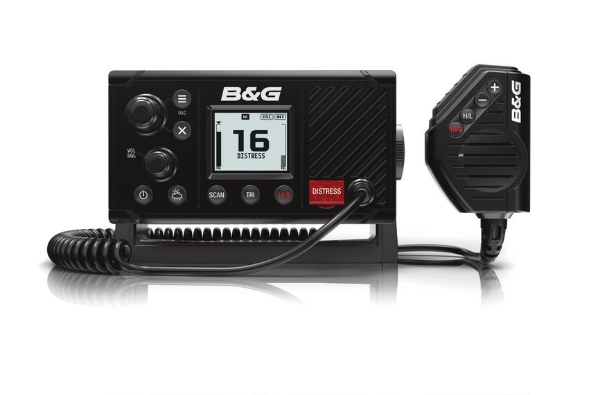
1. VHF radio with hand mic
2. Bracket for gimbal mounting
3. Gasket for recessed mounting
4. Sun cover
5. Documents:
- user’s manual
- warranty card
- mounting template
6. Knobs for bracket
7. bezel trim
8. 8 A (3 AG) spare fuse
9. Bulkhead mount for hand mic
10. 6 pcs 3.5 x 20 mm, stainless steel, panhead phillips
11. 4 pcs 4 x 25 mm, stainless steel, panhead phillips
32 | Installation | V20 operator manualInstallation options
There are two mounting options for the radio:
• Bracket mount:
Using the supplied gimballing bracket the radio can be mounted to
either sit on top of, or hang underneath any flat horizontal surface.
The radio can be removed for storage and the viewing angle can be
adjusted.
• Flush mount:
The radio is recessed into a cavity, showing only the face of the
radio. The radio fixture is permanent and the viewing angle cannot
be adjusted.
Selecting a suitable mounting location
Whichever installation method you choose, please check the
following before doing any cutting or drilling. The chosen location
must:
• Be at least 1 m (3’) from the antenna
• Allow easy access to the rear of the radio for connection to the 12 V
DC electrical source, the antenna and any network wiring
• Be at least 45 cms (1.5’) from a compass to avoid creating magnetic
deviation of the compass.
• Have a suitable space close by for installing the microphone
bulkhead mount
• Provide easy access to the controls on the front panel
Viewing angle
The VHF radio has a large LCD screen with the optimum horizontal
and vertical viewing angles within approx. +/-20 deg. Ensure the
chosen location provides a suitable view of the display. Ideally, the
user should be directly in front of the display or no more than +/-20
deg from the front of the display.
¼¼ Note: If unsure, temporarily power up the radio and ensure the loca-
tion is suitable.
20° 20°
20° 20°
Installation | V20 operator manual | 33Bracket installation
The gimbal bracket provides an adjustable viewing angle with a 20º
tilt range, so ensure the selected mounting location will provide the
desired viewing and operating conditions:
1. Hold the bracket at the chosen location and use a soft pencil to mark the
screw hole positions onto the mounting surface.
2. Use a 3mm (1/8” ) drill bit to drill the 4 pilot holes.
3. Using a Philips screwdriver, secure the bracket using the supplied 4x25mm
self-tapping screws to the mounting location.
4. Fit the radio into the bracket.
5. Insert the two mounting knobs through the holes and tighten them
sufficiently to hold the radio at the desired viewing angle.
6. Fit the mounting clips to the front of the radio to cover dash mount screw
holes.
34 | Installation | V20 operator manualFlush installation
1. Tape the installation template onto the chosen mounting location.
2. Cut out the area marked by the solid dark line (the dashed line indicates the
total area that will be covered by the radio fascia after installation).
3. Use a 2.5mm (3/32” ) drill bit to drill the 4 pilot holes.
4. Remove the installation template.
5. Fit the gasket to the radio.
6. Slide the radio into the cavity.
7. Using a Philips screwdriver, secure the radio using the supplied 3.5x20mm
self-tapping screws to the mounting location.
8. Fit the mounting clips to cover the 4 mounting screws.
Install the hand mic bulkhead bracket
1. Hold the hand mic bulkhead bracket at the chosen location and mark the
screw hole positions on the mounting surface.
¼¼ Note: Ensure that the microphone curly cable will comfortably reach
this location BEFORE you drill.
2. Use a 2.5mm (3/32” ) drill bit to drill the 2 pilot holes.
3. Using a Philips screwdriver, secure the Mic mount using the supplied
3.5x20mm self-tapping screws to the mounting location.
4. Hang the fist mic on the mount.
Installation | V20 operator manual | 35Connect the radio wiring
All wiring on the radio should be done with the vessel power supply
turned off. While radio power is polarity protected, the fuse will
blow if connection is made wrong way round. Ensure any unused
bare wires are isolated from each other, to prevent the potential of
a short circuit. If using the NMEA 2000 connection, ensure network
topology rules are followed closely.
! Warning: never operate the radio without the antenna
connected. This may damage the transmitter.
The connectors are on the rear of the base unit, as follows:
+ _
T T
2
3
4 1
5 8
67
9
10
11
+ _
1. NMEA 2000 network connection. Can be connected to a NMEA 2000
compatible MFD with built in GPS or external GPS antenna.
2. External speaker + (gray): connect to 4 Ohm, 4 Watt (minimum) external
speaker positive
3. External speaker - (gray/black): connect to 4 Ohm, 4 Watt (minimum)
external speaker negative
4. NMEA 0183 RX_A (yellow): connect to TX_A of chart plotter, or active GPS
antenna
5. NMEA 0183 RX_B (green): connect to TX_B of chart plotter, or active GPS
antenna
36 | Installation | V20 operator manual6. NMEA 0183 TX_A (white): connect to RX_A of chart plotter
7. NMEA 0183 TX_B (brown): connect to RX_B of chart plotter
8. GND: optional ground connection. May help with induced noise issues.
9. Antenna: connect to a marine VHF antenna using 50 ohm cable fitted with
a PL-259 connector
10. Battery + (red): connect to vessel’s 12 V DC, via a switch panel or breaker
(comes with inline 8 amp fuse ready fitted)
11. Battery - (black): connect to vessel’s negative busbar
¼¼ Note: external speaker and plotter connections are optional.
First startup configuration
The first time the radio is powered up, the user is prompted to make
a series of setting selections in order to allow the radio to perform
to its full potential. Some steps must be completed; some are
optional and can be completed later. The steps are outlined below
for reference:
Select the region and country the radio will be operated in.
Enter MMSI number if known, or skip to next step. Re-enter number
to confirm correct entry.
¼¼ Note: MMSI entry can only be done once. Changing the MMSI
requires radio be returned to a B&G dealer.
Installation | V20 operator manual | 37For some EU region radios only: Enter the ATIS ID number. Re-enter
number to confirm correct entry.
Enter vessel call sign if known, or skip to next step.
Set the time offset for your region. Choose whether to display time
in 12 or 24 hour.
MMSI and ATIS ID
The MMSI is a unique 9 digit number and the ATIS ID is a 10 digit
number. They are used on marine transceivers that have DSC (Digital
Select Calling) functionality.
• An MMSI remains with a vessel, even if the vessel is sold on.
• An MMSI has 9 numeric digits (xxxxxxxxx). Your MMSI must not
commence with a ‘0’.
• A Group MMSI begins with ‘0’ followed by 8 numeric digits
(0xxxxxxxx).
• A Coast Station MMSI begins with 00 followed by 7 numeric digits
(00xxxxxxx).
• By law, you are not able to change your MMSI once it is entered into
the radio. This is why there is the confirmation screen when entering
the MMSI.
• An ATIS ID is only required in certain EU countries when navigating
some inland waterways. It is usually a different number to your
MMSI.
• If you need to have the MMSI in the radio changed, the radio must
be taken back to your B&G dealer.
ATIS
Automatic Transmitter Identification System (ATIS) is required for
vessels making VHF transmissions whilst on the inland waterways of
38 | Installation | V20 operator manualthe Regional Arrangement Concerning the Radiotelephone Service on Inland Waterways (RAINWAT) signatory countries. RAINWAT is an agreement to implement common principles and rules for the safe carriage of people and goods on Inland Waterways. The signatory countries are: Austria, Belgium, Bulgaria, Croatia, the Czech Republic, France, Germany, Hungary, Luxembourg, Moldova, Montenegro, the Netherlands, Poland, Romania, Serbia, the Slovak Republic and Switzerland. Where a VHF is required on the inland waterways of the signatory countries, this must be capable of ATIS transmissions, and have the feature activated. An ATIS number is required which is issued by Ofcom when you add one or more pieces of ATIS equipment to your Ship Radio Licence. If you don’t have a user MMSI or ATIS ID, contact the appropriate licensing authority in your country. If you’re unsure who to contact, consult your B&G dealer. Installation | V20 operator manual | 39
7
           Specifications
           GENERAL
           Power supply:		               12 V DC battery system
           Nominal operating voltage: + 13.6 V DC
           Low battery alert:		          10.5 V DC +/- 0.5 V
           Over voltage protection:      > 15.8 V +/- 0.5 V
           Current drain (Transmit):     ≤ 6 A @ 25 W / 1.5 A @ 1W (12 V DC)
           Current drain (Receive):      Less than 450 mA in standby
           Replacement Fuse:		           8 A, Glass type 3 AG; 32 mm (1.25”)
           Temperature range:		          -20 ºC to +55 ºC (-4 ºF to 131 ºF)
           Usable channels:		            International, USA, Canada, Weather
           				(country specific)
           Mode:			                      16K0G3E (FM) / 16K0G2B (DSC)
           DSC mode:			                  Class D (Global) with dual receiver
           				(individual CH70)
           Standards - EU:		             EN60950-1, IEC 60529, EN 60945, EN
           				                          301 843-1 V2.1.1, EN301 843-2 V2.1.1,
           				                          EN 301 025 V2.1.1, EN 300 698 V2.1.1
           Standards - US/CAN:		         FCC Part 80, RSS-Gen Issue 4, RSS-182
           				Issue 5
           Standards - INT:		            AS/NZS 4415.1:2003
           Frequency range (Transmitter):156.025 - 157.425 MHz
           Frequency range (Receiver): 156.050 - 163.275 MHz
           Channel spacing:		            25 KHz
           Frequency stability:		        ± 5 ppm
           Frequency control:		          PLL

           PHYSICAL
           LCD display (viewing): 42 mm x 34 mm (1.65” x 1.3”), FSTN
           Contrast control:		    Yes
           Backlight control:		   Yes
           Antenna connector:		   SO-239 (50 ohm)
           Waterproof:			IPx7
           Dimensions:			         W=166.7 mm (6.56”) x H=89.2 mm
           				                   (3.5”) x D=161.4 mm (6.35”) - without
           				bracket
           Weight:			             1.18 kg (2.6 lbs)
40 |       Specifications | V20 operator manual
Compass safe distance: 0.5 m (1.5’) NMEA 0183 port: Yes NMEA 0183 input: RMC, GGA, GLL, GNS NMEA 0183 output: Yes, DSC ( for DSC call), DSE (for enhanced position) NMEA 2000 port: Yes External speaker: Yes FEATURES Flush mount kit Yes Local/Distant control: Yes Position polling: Yes Group call: Yes Call logs: Yes - 20 individual and 10 distress Channel naming: Yes Tri watch: Yes Favourite channel scan: Yes All scan: Yes User programmable MMSI: Yes MMSI and NAME directory: Yes - 20 numbers & group TRANSMITTER Frequency error: ≤± 1.5 KHz Output power: 25 W (23 ± 2) / 1 W (0.8 ± 0.2) Transmitter protection: Open / short circuit of antenna Max Frequency deviation: ≤± 5 Spurious & harmonics Hi/Lo: ≤ 0.25 µ W Modulation Distortion ±3KHz: ≤ 10 % S/N at 3KHz Deviation: ≥ 40 dB Audio Response at 1KHz: +1 to -3dB of 6 dB/octave from 300 hz to 3 KHz DSC TX deviation at 1.3K: 2.6 ± 0.26 KHz DSC TX deviation at 2.1K: 4.2 ± 0.42 KHz ATIS TX deviation at 1.3 KHz: 1.3 ± 0.13 KHz ATIS TX deviation at 2.1 KHz: 2.1 ± 0.21 KHz Specifications | V20 operator manual | 41
RECEIVER
           12dB SINAD sensitivity:           0.25 µV (distant) / 0.8 µV (local)
           20db SINAD sensitivity:           0.35 µV
           Adjacent CH selectivity:          more than 70 db
           Spurious response:		              more than 70 db
           Intermodulation rejection:        more than 68 db
           Residual noise level:		           more than -40 db unsquelched
           Audio output power:		             2 W (with 8 ohm at 10% distortion)
           				                              4 W (with 4 ohm external speaker

       ¼¼ Note: Specifications are subject to change without notice.

42 |       Specifications | V20 operator manual
8
Channel charts
The following channel charts are provided for reference only and
may not be correct for all regions. It is the operators responsibility
to ensure correct channels and frequencies are used for local
regulations.
EU and INTERNATIONAL channel chart
The following is a table of transmiting frequencies in the VHF
maritime mobile band.
¼¼ NOTE: For assistance in understanding the Table, see Notes a) to zz)
below. (WRC-15)
¼¼ NOTE: The Table below defines the channel numbering for maritime
VHF communications based on 25 kHz channel spacing and use of
several duplex channels. The channel numbering and the conver-
sion of two-frequency channels for single-frequency operation shall
be in accordance with Recommendation ITU-R M.1084-5 Annex
4, Tables 1 and 3. The Table below also describes the harmonized
channels where the digital technologies defined in the most recent
version of Recommendation ITU-R M.1842 could be deployed. (WRC-
15)
Channel charts | V20 operator manual | 43Transmitting frequencies
(MHz)
Channel From ship From coast Channel
S/D/R Restriction Notes
designator stations stations name
01 156.050 160.650 D TELEPHONE m)
02 156.100 160.700 D TELEPHONE m)
03 156.150 160.750 D TELEPHONE m)
04 156.200 160.800 D PORT OPS m)
05 156.250 160.850 D PORT OPS/ m)
VTS
06 156.300 156.300 S SAFETY f)
07 156.350 160.950 D PORT OPS m)
08 156.400 156.400 S COMMERCIAL
09 156.450 156.450 S CALLING i)
10 156.500 156.500 S COMMERCIAL h), q)
11 156.550 156.550 S VTS q)
12 156.600 156.600 S PORT OPS/
VTS
13 156.650 156.650 S BRIDGE COM k)
14 156.700 156.700 S PORT OPS/
VTS
15 156.750 156.750 S PORT OPS 1W g)
16 156.800 156.800 S DISTRESS f)
17 156.850 156.850 S SAR 1W g)
18 156.900 161.500 D PORT OPS m)
19 156.950 161.550 D SHIP-SHORE t), u), v)
20 157.000 161.600 D PORT OPS t), u), v)
21 157.050 161.650 D PORT OPS w), y)
22 157.100 161.700 D PORT OPS w), y)
23 157.150 161.750 D TELEPHONE w), x), y)
24 157.200 161.800 D TELEPHONE w), ww),
x), y)
25 157.250 161.850 D TELEPHONE w), ww),
x), y)
26 157.300 161.900 D TELEPHONE w), ww),
x), y)
27 157.350 161.950 D TELEPHONE z)
28 157.400 162.000 D TELEPHONE z)
60 156.025 160.625 D TELEPHONE m)
61 156.075 160.675 D PORT OPS m)
62 156.125 160.725 D PORT OPS m)
63 156.175 160.775 D PORT OPS m)
64 156.225 160.825 D TELEPHONE m)
65 156.275 160.875 D PORT OPS m)
66 156.325 160.925 D PORT OPS m)
67 156.375 156.375 S BRIDGE COM h)
68 156.425 156.425 S SHIP-SHIP
44 | Channel charts | V20 operator manual69 156.475 156.475 S PORT OPS
71 156.575 156.575 S PORT OPS
72 156.625 156.625 S SHIP-SHIP i)
73 156.675 156.675 S PORT OPS h), i)
74 156.725 156.725 S PORT OPS
75 156.775 156.775 S PORT OPS 1W n), s)
76 156.825 156.825 S SHIP-SHIP 1W n), s)
77 156.875 156.875 S SHIP-SHIP
78 156.925 161.525 D SHIP-SHORE t), u), v)
79 156.975 161.575 D PORT OPS t), u), v)
80 157.025 161.625 D PORT OPS w), y)
81 157.075 161.675 D TELEPHONE w), y)
82 157.125 161.725 D TELEPHONE w), x), y)
83 157.175 161.775 D TELEPHONE w), x), y)
84 157.225 161.825 D TELEPHONE w), ww),
x), y)
85 157.275 161.875 D TELEPHONE w), ww),
x), y)
86 157.325 161.925 D TELEPHONE w), ww),
x), y)
87 157.375 157.375 S TELEPHONE z)
88 157.425 157.425 S TELEPHONE z)
1019 156.950 156.950 S TELEPHONE
1020 157.000 157.000 S TELEPHONE
1078 156.925 156.925 S TELEPHONE
1079 156.975 156.975 S TELEPHONE
2006 160.900 160.900 S TELEPHONE r)
2019 161.550 161.550 S TELEPHONE
2020 161.600 161.600 S TELEPHONE
2078 161.525 161.525 S TELEPHONE
2079 161.575 161.575 S TELEPHONE
Editorial note: The note numbering below is provisional and will be
aligned during final preparations of the new edition of the Radio
Regulations.
Notes referring to the Table
General notes:
a) Administrations may designate frequencies in the inter-ship, port
operations and ship movement services for use by light aircraft
and helicopters to communicate with ships or participating coast
stations in predominantly maritime support operations under the
conditions specified in Nos. 51.69, 51.73, 51.74, 51.75, 51.76, 51.77
and 51.78. However, the use of the channels which are shared with
Channel charts | V20 operator manual | 45public correspondence shall be subject to prior agreement between
interested and affected administrations.
b) The channels of the present Appendix, with the exception of
channels 06, 13, 15, 16, 17, 70, 75 and 76, may also be used for
high-speed data and facsimile transmissions,subject to special
arrangement between interested and affected administrations.
c) The channels of the present Appendix, with the exception of
channels 06, 13, 15, 16, 17, 70, 75 and 76, may be used for direct-
printing telegraphy and data transmission, subject to special
arrangement between interested and affected administrations.
(WRC-12)
d) The frequencies in this table may also be used for radio
communications on inland waterways in accordance with the
conditions specified in No.5.226.
e) Administrations may apply 12.5 kHz channel interleaving on a non-
interference basis to 25 kHz channels, in accordance with the most
recent version of Recommendation ITU-R M.1084,provided:
• it shall not affect the 25 kHz channels of the present Appendix
maritime mobile distress and safety, automatic identification
system (AIS), and data exchange frequencies, especially the
channels 06, 13, 15, 16, 17, 70, AIS 1 and AIS 2, nor the technical
characteristics set forth in Recommendation ITU-R M.489-2 for
those channels;
• implementation of 12.5 kHz channel interleaving and
consequential national requirements shall be subject to
coordination with affected administrations. (WRC-12)
Specific notes
f) The frequencies 156.300 MHz (channel 06), 156.525 MHz (channel
70), 156.800 MHz (channel 16), 161.975 MHz (AIS 1) and 162.025 MHz
(AIS 2) may also be used by aircraft stations for the purpose of search
and rescue operations and other safety-related communication.
(WRC-07)
g) Channels 15 and 17 may also be used for on-board communications
provided the effective radiated power does not exceed 1W, and
subject to the national regulations of the administration concerned
when these channels are used in its territorial waters.
h) Within the European Maritime Area and in Canada, these
frequencies (channels 10, 67, 73) may also be used, if so required,
by the individual administrations concerned, for communication
between ship stations, aircraft stations and participating land
stations engaged in coordinated search and rescue and anti-
46 | Channel charts | V20 operator manualYou can also read