VEGAPULS 31 Two-wire 4 20 mA/HART - Operating Instructions - Two-wire 4 20 mA ...
←
→
Page content transcription
If your browser does not render page correctly, please read the page content below
Operating Instructions
Radar sensor for continuous level
measurement

VEGAPULS 31
Two-wire 4 … 20 mA/HART

Document ID: 57820
Contents

Contents
1    About this document................................................................................................................ 4
     1.1 Function............................................................................................................................ 4
     1.2 Target group...................................................................................................................... 4
     1.3 Symbols used................................................................................................................... 4
2    For your safety.......................................................................................................................... 5
     2.1 Authorised personnel........................................................................................................ 5
     2.2 Appropriate use................................................................................................................. 5
     2.3 Warning about incorrect use.............................................................................................. 5
     2.4 General safety instructions................................................................................................ 5
     2.5 Modes for worldwide use.................................................................................................. 6
     2.6 Installation and operation in the USA and Canada............................................................ 6
3    Product description.................................................................................................................. 7
     3.1 Configuration..................................................................................................................... 7
     3.2 Principle of operation........................................................................................................ 9
     3.3 Adjustment........................................................................................................................ 9
     3.4 Packaging, transport and storage.................................................................................... 10
     3.5 Accessories.................................................................................................................... 11
4    Mounting.................................................................................................................................. 12
     4.1 General instructions........................................................................................................ 12
     4.2 Mounting instructions...................................................................................................... 12
     4.3 Measurement setup - Flow.............................................................................................. 16
5    Connecting to power supply.................................................................................................. 19
     5.1 Preparing the connection................................................................................................ 19
     5.2 Connecting...................................................................................................................... 20
     5.3 Wiring plan...................................................................................................................... 21
     5.4 Switch-on phase............................................................................................................. 22
6    Access protection................................................................................................................... 23
     6.1 Bluetooth radio interface................................................................................................. 23
     6.2 Protection of the parameterization................................................................................... 23
     6.3 Storing the codes in myVEGA......................................................................................... 24
7    Set up with the integrated display and adjustment unit..................................................... 25
     7.1 Adjustment system.......................................................................................................... 25
     7.2 Measured value and menu item display.......................................................................... 26
     7.3 Parameter adjustment..................................................................................................... 27
8    Setup with smartphone/tablet (Bluetooth)........................................................................... 35
     8.1 Preparations.................................................................................................................... 35
     8.2 Connecting...................................................................................................................... 35
     8.3 Parameter adjustment..................................................................................................... 36
9    Setup with PC/notebook (Bluetooth).................................................................................... 37
     9.1 Preparations.................................................................................................................... 37
                                                                                                                                                     57820-EN-210422

     9.2 Connecting...................................................................................................................... 37
     9.3 Parameter adjustment..................................................................................................... 38
10 Setup with PC/notebook (VEGACONNECT)......................................................................... 39
   10.1 Connect the PC............................................................................................................... 39

2                                                                                      VEGAPULS 31 • Two-wire 4 … 20 mA/HART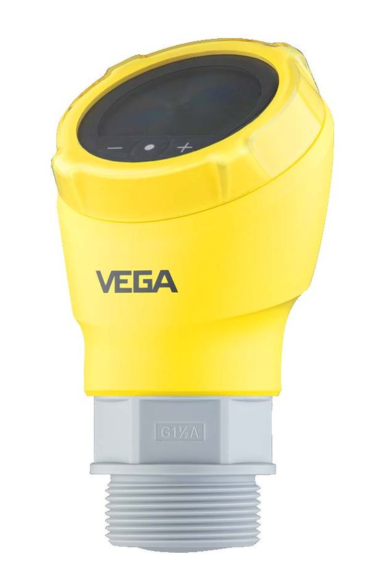
Contents

                       10.2 Parameter adjustment with PACTware............................................................................. 40
                       10.3 Saving the parameterisation data.................................................................................... 41
                  11 Menu overview........................................................................................................................ 42
                     11.1 Display and adjustment unit (on site)............................................................................... 42
                     11.2 VEGA Tools app and DTM (Bluetooth)............................................................................ 43
                  12 Diagnostics and servicing..................................................................................................... 46
                     12.1 Maintenance................................................................................................................... 46
                     12.2 Rectify faults.................................................................................................................... 46
                     12.3 Diagnosis, fault messages.............................................................................................. 47
                     12.4 Status messages according to NE 107........................................................................... 47
                     12.5 Treatment of measurement errors................................................................................... 50
                     12.6 Software update.............................................................................................................. 53
                     12.7 How to proceed if a repair is necessary........................................................................... 54
                  13 Dismount................................................................................................................................. 55
                     13.1 Dismounting steps.......................................................................................................... 55
                     13.2 Disposal.......................................................................................................................... 55
                  14 Certificates and approvals..................................................................................................... 56
                     14.1 Radio licenses................................................................................................................. 56
                     14.2 Approvals for Ex areas.................................................................................................... 56
                     14.3 Approvals as overfill protection........................................................................................ 56
                     14.4 Metrological approvals.................................................................................................... 56
                     14.5 Food and pharmaceutical certificates.............................................................................. 56
                     14.6 EU conformity.................................................................................................................. 56
                     14.7 NAMUR recommendations............................................................................................. 57
                     14.8 Environment management system.................................................................................. 57
                  15 Supplement............................................................................................................................. 58
                     15.1 Technical data................................................................................................................. 58
                     15.2 Dimensions..................................................................................................................... 64
                     15.3 Industrial property rights.................................................................................................. 65
                     15.4 Licensing information for open source software.............................................................. 65
                     15.5 Trademark....................................................................................................................... 65
57820-EN-210422

                                                            Safety instructions for Ex areas
                                                            Take note of the Ex specific safety instructions for Ex applications.
                                                            These instructions are attached as documents to each instrument
                                                            with Ex approval and are part of the operating instructions.
                                                             Editing status: 2021-04-22

                  VEGAPULS 31 • Two-wire 4 … 20 mA/HART                                                                                                       3
1 About this document

                            1     About this document
                            1.1    Function
                            This instruction provides all the information you need for mounting,
                            connection and setup as well as important instructions for mainte-
                            nance, fault rectification, the exchange of parts and the safety of the
                            user. Please read this information before putting the instrument into
                            operation and keep this manual accessible in the immediate vicinity
                            of the device.

                            1.2    Target group
                            This operating instructions manual is directed to trained personnel.
                            The contents of this manual must be made available to the qualified
                            personnel and implemented.

                            1.3    Symbols used
                            Document ID
                            This symbol on the front page of this instruction refers to the Docu-
                            ment ID. By entering the Document ID on www.vega.com you will
                            reach the document download.
                            Information, note, tip: This symbol indicates helpful additional infor-
                            mation and tips for successful work.
                            Note: This symbol indicates notes to prevent failures, malfunctions,
                            damage to devices or plants.
                            Caution: Non-observance of the information marked with this symbol
                            may result in personal injury.
                            Warning: Non-observance of the information marked with this symbol
                            may result in serious or fatal personal injury.
                            Danger: Non-observance of the information marked with this symbol
                            results in serious or fatal personal injury.
                            Ex applications
                            This symbol indicates special instructions for Ex applications.
                        •   List
                            The dot set in front indicates a list with no implied sequence.
                        1   Sequence of actions
                            Numbers set in front indicate successive steps in a procedure.
                            Battery disposal
                            This symbol indicates special information about the disposal of bat-
                            teries and accumulators.
                                                                                                      57820-EN-210422

4                                                          VEGAPULS 31 • Two-wire 4 … 20 mA/HART
2 For your safety
2 For your safety
2.1 Authorised personnel
All operations described in this documentation must be carried out
only by trained, qualified personnel authorised by the plant operator.
During work on and with the device, the required personal protective
equipment must always be worn.
2.2 Appropriate use
VEGAPULS 31 is a sensor for continuous level measurement.
You can find detailed information about the area of application in
chapter " Product description".
Operational reliability is ensured only if the instrument is properly
used according to the specifications in the operating instructions
manual as well as possible supplementary instructions.
2.3 Warning about incorrect use
Inappropriate or incorrect use of this product can give rise to applica-
tion-specific hazards, e.g. vessel overfill through incorrect mounting
or adjustment. Damage to property and persons or environmental
contamination can result. Also, the protective characteristics of the
instrument can be impaired.
2.4 General safety instructions
This is a state-of-the-art instrument complying with all prevailing
regulations and directives. The instrument must only be operated in a
technically flawless and reliable condition. The operator is responsi-
ble for the trouble-free operation of the instrument. When measuring
aggressive or corrosive media that can cause a dangerous situation
if the instrument malfunctions, the operator has to implement suitable
measures to make sure the instrument is functioning properly.
The safety instructions in this operating instructions manual, the na-
tional installation standards as well as the valid safety regulations and
accident prevention rules must be observed by the user.
For safety and warranty reasons, any invasive work on the device
beyond that described in the operating instructions manual may be
carried out only by personnel authorised by the manufacturer. Arbi-
trary conversions or modifications are explicitly forbidden. For safety
reasons, only the accessory specified by the manufacturer must be
used.
To avoid any danger, the safety approval markings and safety tips on
the device must also be observed.
The low transmitting power of the radar sensor is far below the inter-
57820-EN-210422
nationally approved limits. No health impairments are to be expected
with intended use. The band range of the measuring frequency can
be found in chapter " Technical data".
VEGAPULS 31 • Two-wire 4 … 20 mA/HART 52 For your safety
2.5 Modes for worldwide use
Country specific settings for the radar signals are determined via the
operating mode. The operating mode must be set in the operating
menu via the respective adjustment tool at the beginning of the setup
(see chapter " Setup" resp. " Menu overview".
Caution:
Operating the device without selecting the appropriate country group
constitutes a violation of the regulations of the radio approvals of the
respective country.
Further information can be found in the document " Regulations for
radar level measuring instruments with radio licenses" on our home-
page.
2.6 Installation and operation in the USA and
Canada
This information is only valid for USA and Canada. Hence the follow-
ing text is only available in the English language.
Installations in the US shall comply with the relevant requirements of
the National Electrical Code (ANSI/NFPA 70).
Installations in Canada shall comply with the relevant requirements of
the Canadian Electrical Code.
57820-EN-210422
6 VEGAPULS 31 • Two-wire 4 … 20 mA/HART3 Product description
3 Product description
3.1 Configuration
Scope of delivery The scope of delivery encompasses:
• Radar sensor
• Information sheet " Documents and software" with:
–– Instrument serial number
–– QR code with link for direct scanning
• Information sheet " PINs and Codes" (with Bluetooth versions)
with:
–– Bluetooth access code
• Information sheet " Access protection" (with Bluetooth versions)
with:
–– Bluetooth access code
–– Emergency Bluetooth unlock code
–– Emergency device code
The further scope of delivery encompasses:
• Documentation
–– Ex-specific " Safety instructions" (with Ex versions)
–– Radio licenses
–– If necessary, further certificates
Note:
Optional instrument features are also described in this operating
instructions manual. The respective scope of delivery results from the
order specification.
Scope of this operating This operating instructions manual applies to the following instrument
instructions versions:
• Hardware version from 1.0.0
• Software version from 1.2.0
57820-EN-210422
VEGAPULS 31 • Two-wire 4 … 20 mA/HART 73 Product description
Constituent parts
5
4
6
3
2
1
Fig. 1: Components of VEGAPULS 31
1 Radar antenna
2 Process fitting
3 Process seal
4 Electronics housing
5 Display and adjustment unit
6 Ventilation/pressure compensation
Type label The type label contains the most important data for identification and
use of the instrument.
1 VEGAPULS 3.
RA - 222 22N 123
s/n 12345678 6
0044
123456
2 5
3 12...35V
0...15m
4...20mA HART
IP66/IP67, TYPE 4x
MWP 3bar (300kPa) L=5m
PVDF 1½ NPT / 1 NPT www.vega.com
4
D-77761 SCHILTACH,
Made in Germany
Fig. 2: Layout of the type label (example)
1 Instrument type
2 Field for approvals
3 Technical data
4 QR code for device documentation
5 Bluetooth access code
6 Order number
Documents and software Move to " www.vega.com" and enter in the search field the serial
number of your instrument.
There you can find the following information about the instrument:
• Order data
• Documentation
• Software
Alternatively, you can find all via your smartphone:
57820-EN-210422
• Scan the QR-code on the type label of the device or
• Enter serial number manually in the VEGA Tools app (available
free of charge in the respective stores)
8 VEGAPULS 31 • Two-wire 4 … 20 mA/HART3 Product description
3.2 Principle of operation
Application area VEGAPULS 31 is a radar sensor for non-contact, continuous level
measurement. It is suitable for liquids and solids in practically all
industries.
Functional principle The instrument emits a continuous, frequency-modulated radar signal
through its antenna. The emitted signal is reflected by the medium
and received by the antenna as an echo with modified frequency. The
frequency change is proportional to the distance and is converted into
the level.
3.3 Adjustment
Local adjustment On-site adjustment of the device is carried out via the integrated
display and adjustment unit.
Note:
The housing with display and adjustment unit can be rotated 330° for
optimum readability and operability without tools.
Wireless adjustment Devices with integrated Bluetooth module can be adjusted wirelessly
via standard adjustment tools:
• Smartphone/tablet (iOS or Android operating system)
• PC/notebook (Windows operating system)
2
1
3
Fig. 3: Wireless connection to standard operating devices with integrated
Bluetooth LE
1 Sensor
2 Smartphone/Tablet
3 PC/Notebook
Adjustment via the signal Devices with signal output 4 … 20 mA/HART can also be operated
cable via a signal cable. This is done via an interface adapter and a PC/
57820-EN-210422
notebook using DTM/PACTware.
VEGAPULS 31 • Two-wire 4 … 20 mA/HART 93 Product description
2 4
1
CK
LO
TWIST
USB
3
N
OPE
5
Fig. 4: Connecting the PC to the signal cable
1 Sensor
2 HART resistance 250 Ω (optional depending on evaluation)
3 Connection cable with 2 mm pins and terminals
4 Voltage supply
5 Interface adapter VEGACONNECT
3.4 Packaging, transport and storage
Packaging Your instrument was protected by packaging during transport. Its
capacity to handle normal loads during transport is assured by a test
based on ISO 4180.
The packaging consists of environment-friendly, recyclable card-
board. For special versions, PE foam or PE foil is also used. Dispose
of the packaging material via specialised recycling companies.
Transport Transport must be carried out in due consideration of the notes on the
transport packaging. Nonobservance of these instructions can cause
damage to the device.
Transport inspection The delivery must be checked for completeness and possible transit
damage immediately at receipt. Ascertained transit damage or con-
cealed defects must be appropriately dealt with.
Storage Up to the time of installation, the packages must be left closed and
stored according to the orientation and storage markings on the
outside.
Unless otherwise indicated, the packages must be stored only under
the following conditions:
• Not in the open
• Dry and dust free
• Not exposed to corrosive media
•
57820-EN-210422
Protected against solar radiation
• Avoiding mechanical shock and vibration
Storage and transport • Storage and transport temperature see chapter " Supplement -
temperature Technical data - Ambient conditions"
• Relative humidity 20 … 85 %
10 VEGAPULS 31 • Two-wire 4 … 20 mA/HART3 Product description
3.5 Accessories
The instructions for the listed accessories can be found in the down-
load area on our homepage.
Flanges Screwed flanges are available in different versions according to the
following standards: DIN 2501, EN 1092-1, BS 10, ASME B 16.5,
JIS B 2210-1984, GOST 12821-80.
Welded socket, threaded Welded sockets are used to connect the devices to the process,
and hygienic adapter threaded and hygienic adapters for easy adaptation of devices with
standard threaded fittings, e.g. to hygienic connections on the pro-
cess side.
Mounting strap The mounting accessories are used for stable mounting of the device
at the measuring point. The parts are available in various versions and
sizes.
57820-EN-210422
VEGAPULS 31 • Two-wire 4 … 20 mA/HART 114 Mounting
4 Mounting
4.1 General instructions
Ambient conditions The instrument is suitable for standard and extended ambient condi-
tions acc. to DIN/EN/IEC/ANSI/ISA/UL/CSA 61010-1. It can be used
indoors as well as outdoors.
Process conditions Note:
For safety reasons, the instrument must only be operated within the
permissible process conditions. You can find detailed information on
the process conditions in chapter " Technical data" of the operating
instructions or on the type label.
Hence make sure before mounting that all parts of the instrument ex-
posed to the process are suitable for the existing process conditions.
These are mainly:
• Active measuring component
• Process fitting
• Process seal
Process conditions in particular are:
• Process pressure
• Process temperature
• Chemical properties of the medium
• Abrasion and mechanical influences
Protection against mois- Protect your instrument against moisture ingress through the following
ture measures:
• Use a suitable connection cable (see chapter " Connecting to
power supply")
• Tighten the cable gland or plug connector
• Lead the connection cable downward in front of the cable entry or
plug connector
This applies mainly to outdoor installations, in areas where high
humidity is expected (e.g. through cleaning processes) and on cooled
or heated vessels.
Note:
Make sure that during installation or maintenance no moisture or dirt
can get inside the instrument.
To maintain the housing protection, make sure that the housing lid is
closed during operation and locked, if necessary.
4.2 Mounting instructions
Polarisation Radar sensors for level measurement emit electromagnetic waves.
57820-EN-210422
The polarization is the direction of the electrical component of these
waves.
The polarization direction is marked on the housing, see following
drawing:
12 VEGAPULS 31 • Two-wire 4 … 20 mA/HART4 Mounting
1
Fig. 5: Position of the polarisation
1 Marking of the polarisation
Note:
When the housing is rotated, the direction of polarization changes
and hence the influence of the false echo on the measured value.
Please keep this in mind when mounting or making changes later.
Reference plane The centre of the antenna lens is the beginning of the measuring
range and at the same time the reference plane for the min./max.
adjustment, see following diagram:
1
Fig. 6: Reference plane
1 Reference plane
Installation position When mounting the device, keep a distance of at least 200 mm
(7.874 in) from the vessel wall. If the device is installed in the center
of dished or round vessel tops, multiple echoes can arise. However,
these can be suppressed by an appropriate adjustment (see chapter
" Set up").
If you cannot maintain this distance, you should carry out a false
signal suppression during setup. This applies particularly if buildup on
the vessel wall is expected. In such cases, we recommend repeating
the false signal suppression at a later date with existing buildup.
> 200 mm
(7.87")
57820-EN-210422
Fig. 7: Mounting of the radar sensor on round vessel tops
In vessels with conical bottom it can be advantageous to mount the
device in the centre of the vessel, as measurement is then possible
down to the bottom.
VEGAPULS 31 • Two-wire 4 … 20 mA/HART 134 Mounting
Fig. 8: Mounting of the radar sensor on vessels with conical bottom
Inflowing medium Do not mount the instruments in or above the filling stream. Make sure
that you detect the medium surface, not the inflowing product.
Fig. 9: Mounting of the radar sensor with inflowing medium
Threaded socket und With threaded connection, the antenna end should protrude at least
socket piece 5 mm (0.2 in) out of the nozzle.
ca. 5 mm
Fig. 10: Thread mounting
If the reflective properties of the medium are good, you can mount
VEGAPULS 31 on sockets longer than the antenna. The socket end
should be smooth and burr-free, if possible also rounded.
You will find recommended values for socket heights in the following
57820-EN-210422
illustration or the table. The values come from typical applications.
Deviating from the proposed dimensions, also longer sockets are
possible, however the local conditions must be taken into account.
14 VEGAPULS 31 • Two-wire 4 … 20 mA/HART4 Mounting
h
d
Fig. 11: Socket mounting
Socket diameter d Socket length h
40 mm 1½" ≤ 150 mm ≤ 5.9 in
50 mm 2" ≤ 200 mm ≤ 7.9 in
80 mm 3" ≤ 300 mm ≤ 11.8 in
100 mm 4" ≤ 400 mm ≤ 15.8 in
150 mm 6" ≤ 600 mm ≤ 23.6 in
Note:
When mounting on longer nozzles, we recommend carrying out a
false signal suppression (see chapter " Parameter adjustment").
Vessel installations The mounting location of the radar sensor should be a place where no
other equipment or fixtures cross the path of the radar signals.
Vessel installations, such as e.g. ladders, limit switches, heating spi-
rals, struts, etc., can cause false echoes and impair the useful echo.
Make sure when planning your measuring point that the radar sensor
has a " clear view" to the measured product.
In case of existing vessel installations, a false signal suppression
should be carried out during setup.
If large vessel installations such as struts or supports cause false
echoes, these can be attenuated through supplementary measures.
Small, inclined sheet metal baffles above the installations " scatter"
the radar signals and prevent direct interfering reflections.
Fig. 12: Cover flat, large-area profiles with deflectors
Orientation In liquids, direct the device as perpendicular as possible to the me-
dium surface to achieve optimum measurement results.
57820-EN-210422
VEGAPULS 31 • Two-wire 4 … 20 mA/HART 154 Mounting
Fig. 13: Alignment in liquids
Agitators If there are agitators in the vessel, a false signal suppression should
be carried out with the agitators in motion. This ensures that the
interfering reflections from the agitators are saved with the blades in
different positions.
Fig. 14: Agitators
Foam generation Through the action of filling, stirring and other processes in the vessel,
compact foams which considerably damp the emitted signals may
form on the medium surface.
If foams lead to measurement errors, you should use the biggest pos-
sible radar antennas or sensors with guided radar.
4.3 Measurement setup - Flow
Mounting In general, the following must be observed while mounting the device:
• Mounting the sensor on the upstream or inlet side
• Installation in the centre of the flume and vertical to the liquid
surface
• Distance to the overfall orifice or Venturi flume
• Min. distance to the max. height of the orifice or flume for optimum
accuracy: 250 mm (9.843 in) 1)
•
57820-EN-210422
Requirements from approvals for flow measurement, e.g.
MCERTS
1)
At smaller distances the measuring accuracy is reduced, see "Technical
data".
16 VEGAPULS 31 • Two-wire 4 … 20 mA/HART4 Mounting
Flume Every flume generates a different level of backwater depending on its
type and version. The specifications of the following flumes are avail-
able in the instrument:
Predefined curves
A flow measurement with these standard curves is very easy to set
up, as no dimensional information of the flume is required.
• Palmer-Bowlus flume (Q = k x h1.86)
• Venturi, trapezoidal weir, rectangular flume (Q = k x h1.5)
• V-Notch, triangular overfall (Q = k x h2.5)
Dimensions (ISO standard)
When selecting these curves, the dimensions of the flume must be
known and entered via the assistant. As a result, the accuracy of the
flow measurement is higher than with the specified curves.
• Rectangular flume (ISO 4359)
• Trapezoidal flume (ISO 4359)
• U-shaped flume (ISO 4359)
• Triangular overfall thin-walled (ISO 1438)
• Rectangular flume thin-walled (ISO 1438)
• Rectangular weir broad crown (ISO 3846)
Flow formula
If the flow formula of your flume is known, you should select this op-
tion, as the accuracy of the flow measurement is highest here.
• Flow formula: Q = k x hexp
Manufacturer definition
If you use a Parshall flume from the manufacturer ISCO, this option
must be selected. This gives you a high accuracy of flow measure-
ment with easy configuration.
Alternatively, you can also take over Q/h table values provided by the
manufacturer here.
• ISCO Parshall flume
• Q/h table (assignment of height with corresponding flow in a table)
Detailed project planning data can be found at the channel manufac-
turers and in the technical literature.
The following examples serve as an overview for flow measurement.
57820-EN-210422
VEGAPULS 31 • Two-wire 4 … 20 mA/HART 174 Mounting
Rectangular overfall
1
≥ 250 mm
≥ 250 mm
3 ... 4 hmax
(9.84")
(9.84")
90°
90°
hmax
≥ 2 x hmax
2 2 33 4
Fig. 15: Flow measurement with rectangular flume: hmax. = max. filling of the
rectangular flume
1 Overfall orifice (side view)
2 Upstream water
3 Tailwater
4 Overfall orifice (view from tailwater)
Khafagi-Venturi flume
≥ 250 mm
3 ... 4 x hmax
(9.84")
90°
hmax
1 B 2
Fig. 16: Flow measurement with Khafagi-Venturi flume: hmax. = max. filling of the
flume; B = tightest constriction in the flume
1 Position sensor
2 Venturi flume
57820-EN-210422
18 VEGAPULS 31 • Two-wire 4 … 20 mA/HART5 Connecting to power supply
5 Connecting to power supply
5.1 Preparing the connection
Safety instructions Always keep in mind the following safety instructions:
• Carry out electrical connection by trained, qualified personnel
authorised by the plant operator
Warning:
Only connect or disconnect in de-energized state.
Voltage supply The data for power supply are specified in chapter " Technical data".
Note:
Power the instrument via an energy-limited circuit (power max. 100 W)
acc. to IEC 61010-1, e.g.
• Class 2 power supply unit (acc. to UL1310)
• SELV power supply unit (safety extra-low voltage) with suitable
internal or external limitation of the output current
Keep in mind the following additional factors that influence the operat-
ing voltage:
• Lower output voltage of the power supply unit under nominal load
(e.g. with a sensor current of 20.5 mA or 22 mA in case of fault)
• Influence of additional instruments in the circuit (see load values in
chapter " Technical data")
Connection cable Use cable with round cross section for instruments with housing and
cable gland. To ensure the seal effect of the cable gland (IP protection
rating), find out which cable outer diameter the cable gland is suitable
for.
The instrument is connected with standard two-wire cable. If electro-
magnetic interference is expected which is above the test values of
EN 61326-1 for industrial areas, shielded cable should be used.
Note:
Shielded cable generally necessary in HART multidrop mode.
Note:
If the temperatures are too high, the cable insulation can be dam-
aged. Hence keep apart from the ambient temperature also the self-
heating of the instrument for the temperature resistance of the cable
in the connection compartment in mind 2).
Cable screening and We recommend to connect the cable screening to ground potential at
grounding one end on the supply side when using shielded cable.
57820-EN-210422
2)
With an ambient temperature ≥ 50 °C (122 °F) the connection cable should
be suitable for a temperature which is at least 20 °C (36 °F) higher.
VEGAPULS 31 • Two-wire 4 … 20 mA/HART 195 Connecting to power supply
Cable gland Metric threads
In the case of instrument housings with metric thread, the cable gland
is screwed in at the factory. It is sealed with plastic plugs as transport
protection.
You have to remove this plug before electrical connection.
NPT thread
In the case of instrument housings with self-sealing NPT threads, it
is not possible to have the cable entry screwed in at the factory. The
cable gland is therefore covered with a red dust protection cap as
transport protection.
Note:
To ensure the housing protection class, you must replace this protec-
tive cap with an approved NPT cable gland before setup.
Note:
Do not use grease when screwing in the NPT cable gland or a conduit
steel pipe.
Maximum torque see chapter " Technical data".
5.2 Connecting
Connection technology The voltage supply and signal output are connected via the spring-
loaded terminals in the housing.
Note:
Fixed conductors and flexible conductors with ferrules can be
inserted directly into the terminal openings. In the case of flexible
conductors for opening the terminals, use a screwdriver (3 mm blade
width) to push the actuator lever away from the terminal opening.
When released, the terminals are closed again.
57820-EN-210422
20 VEGAPULS 31 • Two-wire 4 … 20 mA/HART5 Connecting to power supply
Fig. 17: Connection
You can find further information on the max. wire cross-section under
" Technical data - Electromechanical data".
Connecting Connect the instrument according to the following wiring plan.
5.3 Wiring plan
Electronics and connec-
tion compartment
(+)1 2(-)
2
1
57820-EN-210422
Fig. 18: Connection compartment VEGAPULS 31
1 Voltage supply, signal output
2 Plug connector for display and adjustment unit
VEGAPULS 31 • Two-wire 4 … 20 mA/HART 215 Connecting to power supply
5.4 Switch-on phase
After connection to the power supply, the device carries out a self-
test:
• Internal check of the electronics
• Output signal is set to failure
The current measured value is then output on the signal cable.
57820-EN-210422
22 VEGAPULS 31 • Two-wire 4 … 20 mA/HART6 Access protection
6 Access protection
6.1 Bluetooth radio interface
Devices with a Bluetooth radio interface are protected against un-
wanted access from outside. This means that only authorized persons
can receive measured and status values and change device settings
via this interface.
Bluetooth access code A Bluetooth access code is required to establish Bluetooth com-
munication via the adjustment tool (smartphone/tablet/notebook).
This code must be entered once when Bluetooth communication is
established for the first time in the adjustment tool. It is then stored in
the adjustment tool and does not have to be entered again.
The Bluetooth access code is individual for each device. It is printed
on the device housing and is also supplied with the device in the infor-
mation sheet " PINs and Codes". It can be changed by the user after
the first connection has been established. If the Bluetooth access
code has not been entered correctly, a new entry can only be made
after a waiting period has elapsed. The waiting time increases with
each additional incorrect entry.
Emergency Bluetooth The emergency Bluetooth access code enables Bluetooth communi-
unlock code cation to be established in the event that the Bluetooth access code
is no longer known. It can't be changed. The emergency Bluetooth
access code can be found in information sheet " Access protection".
If this document is lost, the emergency Bluetooth access code can
be retrieved from your personal contact person after legitimation.
The storage and transmission of Bluetooth access codes is always
encrypted (SHA 256 algorithm).
6.2 Protection of the parameterization
The settings (parameters) of the device can be protected against un-
wanted changes. The parameter protection is deactivated on delivery,
all settings can be made.
Device code To protect the parameterization, the device can be locked by the user
with the aid of a freely selectable device code. The settings (param-
eters) can then only be read out, but not changed. The device code
is also stored in the adjustment tool. However, unlike the Bluetooth
access code, it must be re-entered for each unlock. When using the
adjustment app or DTM, the stored device code is then suggested to
the user for unlocking.
Emergency device code The emergency device code allows unlocking the device in case the
device code is no longer known. It can't be changed. The emergency
device code can also be found on the supplied information sheet " Ac-
57820-EN-210422
cess protection". If this document is lost, the emergency device code
can be retrieved from your personal contact person after legitimation.
The storage and transmission of the device codes is always encrypt-
ed (SHA 256 algorithm).
VEGAPULS 31 • Two-wire 4 … 20 mA/HART 236 Access protection
6.3 Storing the codes in myVEGA
If the user has a " myVEGA" account, then the Bluetooth access code
as well as the device code are additionally stored in his account under
" PINs and Codes". This greatly simplifies the use of additional adjust-
ment tools, as all Bluetooth access and device codes are automati-
cally synchronized when connected to the " myVEGA" account
57820-EN-210422
24 VEGAPULS 31 • Two-wire 4 … 20 mA/HART7 Set up with the integrated display and adjustment unit
7 Set up with the integrated display and
adjustment unit
7.1 Adjustment system
Function The instrument is operated via the three keys of the integrated display
and adjustment unit. The respective menu items are shown on the LC
display. You can find the function of the individual keys in the below
overview.
Certain settings are only possible to a limited extent or not possible
with the integrated display and adjustment unit. For these settings, we
recommend using the adjustment app or PACTware with correspond-
ing DTM.
Display and adjustment
elements
1
2
Fig. 19: Elements of the integrated display and adjustment unit
1 LC display
2 Adjustment keys
Key functions
Key Function
[•] Entry to the menu level
Jump to selected menu item
Edit parameter
Select editing position
Save value
[+] Switching between the individual measured value windows
Navigation in the menu items, forwards
Change parameter values upwards
[-] Switching between the individual measured value windows
Navigation in the menu items, backwards
Change parameter values downwards
[+] and [-] Jump to next higher menu
57820-EN-210422
simultane- Interrupt input
ously
VEGAPULS 31 • Two-wire 4 … 20 mA/HART 257 Set up with the integrated display and adjustment unit
Time functions When the [+] and [-] keys are pressed quickly, the edited value, or the
cursor, changes one value or position at a time. If the key is pressed
longer than 1 s, the value or position changes continuously.
Simultaneous pressing of the [+] and [-] keys causes a return to the
measured value indication.
Approx. 60 minutes after the last pressing of a key, an automatic reset
to measured value indication is triggered. Any values not confirmed
with [Ο] will not be saved.
7.2 Measured value and menu item display
Measured value indica- The measured values are displayed according to the following pres-
tion entation:
2
2.541
m
1 3
Fig. 20: Measured value display (example)
1 Measured value as bargraph
2 Digital value
3 Unit
Menu item display The menu items are displayed according to the following presentation:
1
Max. Adjustment 2
1.0000 m
Fig. 21: Menu item display (example)
1 Menu item
2 Actual parameter value
57820-EN-210422
26 VEGAPULS 31 • Two-wire 4 … 20 mA/HART7 Set up with the integrated display and adjustment unit
7.3 Parameter adjustment
7.3.1 Main menu
Medium This menu item enables you to adapt the sensor to the different meas-
uring conditions of the media " Liquid" or " Bulk solid". This selection
adapts the signal processing to the expected reflections.
Application This menu item enables you to optimally adapt the sensor to the ap-
plication, the place of use and the measuring conditions. The adjust-
ment possibilities depend on the selection made under " Medium", "
Liquid" or " Bulk solid".
The vessels as well as the measuring and process conditions are
described in the following as an overview.
Application - liquid With " Liquid", the applications are based on the following features,
to which the measuring characteristic of the sensor is adjusted in
particular:
Storage tank
• Vessel:
–– Large volume
–– Upright cylindrical, horizontal round
• Process/measurement conditions:
–– Slow filling and emptying
–– Smooth medium surface
–– Multiple reflections from dished vessel ceiling
–– Condensation
Stirrer vessel
• Vessel:
–– Large agitator blades of metal
–– Installations like flow breakers, heating spirals
57820-EN-210422
–– Nozzle
• Process/measurement conditions:
–– Frequent, fast to slow filling and emptying
–– Strongly agitated surface, foam and strong vortex generation
–– Multiple reflections through dished vessel ceiling
VEGAPULS 31 • Two-wire 4 … 20 mA/HART 277 Set up with the integrated display and adjustment unit
–– Condensation, buildup on the sensor
• Further recommendations
–– False signal suppression with running agitator via adjustment
app or PACTware/DTM
Dosing vessel
• Vessel:
–– Small vessels
• Process/measurement conditions:
–– Frequent and fast filling/emptying
–– Tight installation situation
–– Multiple reflections through dished vessel ceiling
–– Product buildup, condensate and foam generation
Pumping station/Pump shaft
• Process/measurement conditions:
–– Partly strongly agitated surface
–– Installations such as pumps and ladders
–– Multiple reflections through flat vessel ceiling
–– Dirt and grease deposits on shaft wall and sensor
–– Condensation on the sensor
• Further recommendations
–– False signal suppression via adjustment app or PACTware/DTM
Overflow basin
• Vessel
–– Large volume
–– Partly installed underground
• Process/measurement conditions:
–– Partly strongly agitated surface
–– Multiple reflections through flat vessel ceiling
–– Condensation, dirt deposits on the sensor
–– Flooding of the sensor antenna
Vessel/Collecting basin
• Vessel:
–– Large volume
–– Upright cylindrical or rectangular
• Process/measurement conditions:
–– Slow filling and emptying
–– Smooth medium surface
–– Condensation
Plastic tank (measurement through the vessel top)
• Process/measurement conditions:
–– Measurement through the tank top, if appropriate to the applica-
tion
–– Condensation on the plastic ceiling
57820-EN-210422
–– In outdoor facilities, water and snow on vessel top possible
• Further recommendations
–– With measurement through the tank top false signal suppres-
sion via adjustment app or PACTware/DTM
28 VEGAPULS 31 • Two-wire 4 … 20 mA/HART7 Set up with the integrated display and adjustment unit
–– When measuring through the tank top in outdoor areas protec-
tive roof for the measuring point
Transportable plastic tank (IBC)
• Process/measurement conditions:
–– Material and thickness different
–– Measurement through the vessel top, if appropriate to the
application
–– Changed reflection conditions as well as jumps in measured
values when changing vessels
• Further recommendations
–– With measurement through the tank top false signal suppres-
sion via adjustment app or PACTware/DTM
–– When measuring through the tank top in outdoor areas protec-
tive roof for the measuring point
Gauge measurement in waters
• Process/measurement conditions:
–– Slow gauge change
–– Extreme damping of output signal in case of wave generation
–– Ice and condensation on the antenna possible
–– Floating debris sporadically on the water surface
Flow measurement flume/Overfall
• Process/measurement conditions:
–– Slow gauge change
–– Smooth to agitated water surface
–– Measurement often from a short distance with the demand for
accurate measurement results
–– Ice and condensation on the antenna possible
Demonstration
• Applications that are not typical level measurements, e.g. device
tests
–– Instrument demonstration
–– Object recognition/monitoring
–– Fast position changes of a measuring plate during functional
test
Application - bulk solid With " Bulk solid", the applications are based on the following fea-
tures, to which the measuring characteristic of the sensor is adjusted
in particular:
Silo (slender and high)
• Process/measurement conditions:
–– Interfering reflections due to weld seams on the vessel
–– Multiple echoes/diffuse reflections due to unfavourable pouring
positions with fine grain
57820-EN-210422
–– Varying pouring positions due to outlet funnel and filling cone
• Further recommendations
–– False signal suppression via adjustment app or PACTware/DTM
–– Alignment of the measurement to the silo outlet
VEGAPULS 31 • Two-wire 4 … 20 mA/HART 297 Set up with the integrated display and adjustment unit
Bunker (large-volume)
• Process/measurement conditions:
–– Large distance to the medium
–– Steep angles of repose, unfavourable pouring positions due to
outlet funnel and filling cone
–– Diffuse reflections due to structured vessel walls or internals
–– Multiple echoes/diffuse reflections due to unfavourable pouring
positions with fine grain
–– Changing signal conditions when large amounts of material slip
off
• Further recommendations
–– False signal suppression via adjustment app or PACTware/DTM
Heap (point measurement/profile detection)
• Process/measurement conditions:
–– Measured value jumps, e.g. through heap profile and traverses
–– Large angles of repose, varying pouring positions
–– Measurement near the filling stream
–– Sensor mounting on movable conveyor belts
Crusher
• Process/measurement conditions:
–– Measured value jumps and varying pouring positions, e.g. due
to truck filling
–– Fast reaction time
–– Large distance to the medium
–– Interfering reflections from fixtures or protective devices
• Further recommendations
–– False signal suppression via adjustment app or PACTware/DTM
Demonstration
• Applications that are not typical level measurements
–– Instrument demonstration
–– Object recognition/monitoring
–– Measured value verification with higher measuring accuracy
with reflection without bulk solids, e.g. via a measuring plate
Unit distance In this menu item you select the unit for measured distance in mm, m,
in or ft.
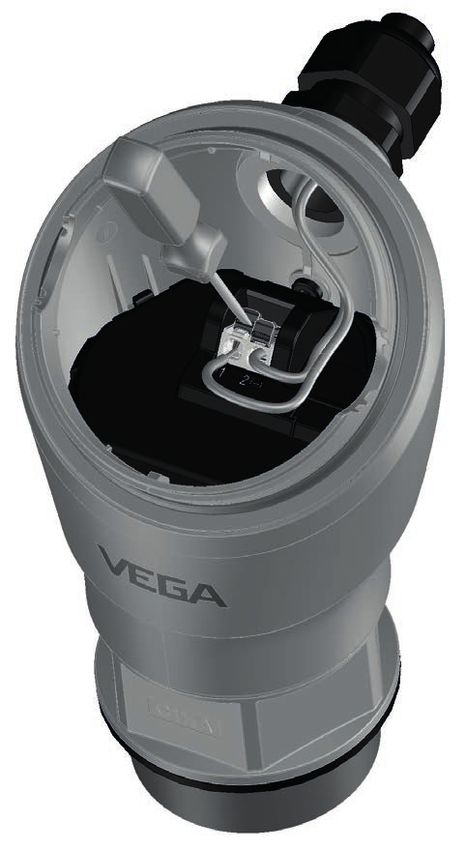
Adjustment Since the radar sensor is a distance measuring instrument, it is the
distance from the sensor to the medium surface that is measured. To
indicate the actual level, the measured distance must be assigned to
a certain height percentage.
57820-EN-210422
30 VEGAPULS 31 • Two-wire 4 … 20 mA/HART7 Set up with the integrated display and adjustment unit
To perform the adjustment, enter the distance with full and empty ves-
sel, see the following example:
3
100% 2
(19.68")
0,5 m
(196.9")
5m
0% 1
Fig. 22: Parameterisation example, Min./max. adjustment
1 Min. level = max. measuring distance
2 Max. level = min. measuring distance
3 Reference plane
The starting point for these distance specifications is always the refer-
ence plane, i.e. the lower edge of the sensor. Information on the refer-
ence plane can be found in the chapters " Mounting" and " Technical
data". The actual filling height is then calculated on the basis of these
entries.
The actual product level during this adjustment is not important,
because the min./max. adjustment is always carried out without
changing the product level. These settings can be made ahead of
time without the instrument having to be installed.
7.3.2 Extended functions
Displayed value In the menu item " Display value" you define the indication of the
measured values on the indication as filling height, distance, percent,
lin. percent or scaled.
Scaling In the menu item " Scaling" you define how the level value is shown
on the indication. This includes the scaling size, unit and format as
well as the assignment to 0 % and 100 % of the measured value.
Scaling makes it possible, for example, to display the volume in m³.
57820-EN-210422
VEGAPULS 31 • Two-wire 4 … 20 mA/HART 317 Set up with the integrated display and adjustment unit
Menu language This menu item enables the setting of the requested national lan-
guage for the display.
The following languages are available:
German, English, French, Spanish, Portuguese, Italian, Dutch, Rus-
sian, Chinese, Japanese, Turkish
Bluetooth access code In this menu item, you can change the factory-preset Bluetooth ac-
cess code to your personal Bluetooth access code.
Note:
The individual preset Bluetooth access code of the device can be
found on the supplied information sheet " PINs and Codes". If this is
changed by the user and is no longer available, access is only pos-
sible via the emergency Bluetooth unlock code on the information
sheet " Emergency unlock codes" also supplied.
For instruments without Bluetooth function, this menu item displays "
Instrument without Bluetooth".
Protection of the param- In the menu item " Protection of the parameter adjustment" you
eterization protect the sensor parameters against unwanted or unintentional
changes by entering a device code.
With activated protection of the parameter adjustment, the individual
menu items can be selected and displayed, however the parameters
can no longer be modified.
Releasing the sensor adjustment is also possible in any menu item by
entering the device code.
Note:
The factory set device code is " 000000". If this is changed by the
user and is no longer available, access is only possible via the
emergency device unlock code on the information sheet " Emergency
unlock codes" also supplied.
57820-EN-210422
Caution:
With protected parameter adjustment, adjustment via the adjustment
app as well as PACTware/DTM and other systems is also blocked.
32 VEGAPULS 31 • Two-wire 4 … 20 mA/HART7 Set up with the integrated display and adjustment unit
Reset During a reset, parameter settings made by the user are reset to the
values of the basic setting or the delivery status (see chapter " Menu
overview") 3).
Caution:
For the duration of the reset, the set trouble signal is output via the
current output. Within the context of the asset management function,
the message " Maintenance" is output.
The following reset functions are available:
Basic settings:
Reset the parameter settings to the default values of the respective
device. You will find the values in chapter " Menu overview".
Note:
Order-related settings are not taken over into the current parameters
after this reset. The currently set menu language is not reset.
Delivery status:
Resetting of the parameter adjustments to delivery status
Mode Country specific settings for the radar signals are determined via the
operating mode.
• Mode 1: EU, Albania, Andorra, Azerbaijan, Australia, Belarus, Bos-
nia and Herzegovina, Canada, Liechtenstein, Moldavia, Monaco,
Montenegro, New Zealand, Northern Macedonia, Norway, San
Marino, Saudi Arabia, Serbia, Switzerland, Turkey, Ukraine, United
Kingdom, USA
• Mode 2: South Korea, Taiwan,Thailand
• Mode of operation 3: India, Malaysia, South Africa
• Mode of operation 4: Russia, Kazakhstan
Depending on the operating mode, the metrological properties of the
device can change (see chapter " Technical data, input variable").
57820-EN-210422
7.3.3 Diagnostics
Status In this menu item, the device status is displayed.
3)
Language and Bluetooth access code are not reset.
VEGAPULS 31 • Two-wire 4 … 20 mA/HART 337 Set up with the integrated display and adjustment unit
Measurement reliability The measurement reliability represents the signal strength of the level
echo above the detection threshold in dB. This makes it possible to
assess the quality of the measurement. The measurement reliability
should be at least 20 dB.
Sensor information The menu item " Sensor information" provides the device name and
serial number as well as the hardware and software version.
57820-EN-210422
34 VEGAPULS 31 • Two-wire 4 … 20 mA/HARTYou can also read