(IBS) Vehicle Control Using CAN Protocol For Implementing the Intelligent Braking System
←
→
Page content transcription
If your browser does not render page correctly, please read the page content below
ISSN (Print) : 2320 – 3765
                                                                                            ISSN (Online): 2278 – 8875

      International Journal of Advanced Research in Electrical,
            Electronics and Instrumentation Engineering
                                    (An ISO 3297: 2007 Certified Organization)

                                         Vol. 3, Issue 3, March 2014

    Vehicle Control Using CAN Protocol For
  Implementing the Intelligent Braking System
                     (IBS)
                                    R. Manoj Prasanth1, S.Raja2, L.Saranya3

       UG Student [ECE] , Dept. of ECE, Christ the King Engineering College, Coimbatore, Tamilnadu, India 1
         Assistant professor, Dept. of ECE, Christ the King Engineering College, Coimbatore, Tamilnadu, India 2
         Assistant professor, Dept. of ECE, Christ the King Engineering College, Coimbatore, Tamilnadu, India 3
Abstract: The main purposes of Present Automobiles are being developed by more of electrical parts for efficient
operation. Generally a vehicle was built with an analogue driver-vehicle interface for indicating various vehicle statuses
like speed, fuel level, Engine temperature etc., This paper presents the development and implementation of a digital
driving system for a semi-autonomous vehicle to improve the driver-vehicle interface. It uses a PIC based data
acquisition system that uses ADC to bring all control data from analogue to digital format and visualize through LCD.
This paper presents the development of distance measurement using Ultrasonic sensors which denotes that vehicle’s
position from obstacles. The vehicle detects the speed breaker& some critical zones before the certain limitation by tags
using RFID module for introducing the new technology of priority based Intelligent Braking System (IBS).

Internal systems: CAN bus, LCD display, Ultrasonic sensor, controlling sensors, RFID module ,etc.

                                                I.       INTRODUCTION

           The protocol was developed aiming at automotive applications. Today CAN have gained wide spread use and
is used in industrial automation as well as in automotives and mobile machines. The CAN protocol is implemented in
silicon. This makes it possible to combine the error handling and fault confinement facilities of CAN with a high
transmission speed. The method used for distributing messages to the right receivers contributes to gaining a good use
of the available bandwidth. This requires a simple transmission medium. A common transmission medium is a twisted
pair of wires.. The development of CAN began when more and more electronic devices were implemented into modern
motor vehicles. Examples of such devices include engine management systems, active suspension, ABS, gear control,
lighting control, air conditioning, airbags and central locking. So, it is important that human drivers still have some
control over the vehicle. Advanced in-vehicle information systems provide vehicles with different types and levels of
intelligence to assist the driver. The introduction into the vehicle design has allowed an almost symbiotic relationship
between the driver and vehicle by providing a sophisticated & intelligent driver-vehicle interface through an intelligent
information network. This paper discusses the development of such a control framework for the vehicle which is called
the digital-driving behaviour, which consists of a joint mechanism between the driver and vehicle for perception,
decision making and control. All this means more safety and more comfort for the driver and of course a reduction of
fuel consumption and exhaust emissions. The complexities of these control systems, and the need to exchange data
between them meant that more and more hard-wired, dedicated signal lines had to be provided. Sensors had to be
duplicated if measured parameters were needed by different controllers. Each device can decide if a message is relevant
or if it should be filtered. This structure allows modifications to CAN networks with minimal impact. Additional non-
transmitting nodes can be added without modification to the network .Fig.1 shows that the CAN bus significantly
reduce the wiring. A vehicle was generally built with an analogue driver vehicle interface for indicating various
parameters of vehicle status like temperature, pressure and speed etc. A microcontroller based data acquisition system
that uses ADC to bring all control data from analogue to digital format is used. Since the vehicle information systems
are spread out all over the body of a practical vehicle, a communication module that supports to implement a one stop
control of the vehicle through the master controller of the digital driving system. The proposed high-speed CAN bus
system solves the problem of automotive system applications, also has a certain practical value and significance.
Copyright to IJAREEIE                                     www.ijareeie.com                                        7597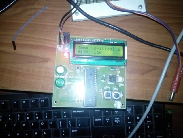
ISSN (Print) : 2320 – 3765
                                                                                           ISSN (Online): 2278 – 8875

      International Journal of Advanced Research in Electrical,
            Electronics and Instrumentation Engineering
                                  (An ISO 3297: 2007 Certified Organization)

                                        Vol. 3, Issue 3, March 2014

The literature survey of CAN protocol in automation includes the following are,
                                  Table-1: Literature survey of CAN in automation.

                    1983    Start of the Bosch internal project to develop an in-vehicle network

                    1991    Bosch’s CAN specification 2.0 published

                    1992    CAN in Automation (cia) international users and manufacturers group
                            established

                    1992    First cars from Mercedes-Benz used CAN network

                    2000    Development of the time-triggered communication protocol for CAN
                            (TTCAN)

         With PIC as the main controller and it makes full use of the high-performance of PIC18f458, high-speed
reduction of CAN bus communication control networks and instrument control. so ,as to achieve full sharing of data
between nodes and enhance their collaborative work. This system features efficient data transfer among different nodes
in the practical applications. And it introduced the distance measurement using ultrasonic sensors. This proposed
system provides the intelligent breaking system using RFID module at automatic braking system enabled vehicles.

                                     Fig 1. Existing and Proposed vehicle control system

                                      II. HARDWARE STRUCTURE
A. CAN bus
1. CAN Bus in an Automobile
          CAN is a LAN (Local Area Network) controller CAN bus can transfer the serial data one by one. Fig 2 shows
a typical architecture from an automotive. All participants in the CAN bus subsystems are accessible via the control
unit on the CAN bus is a multi-channel transmission system. When a unit fails, it does not affect others. The data
transfer rate of CAN bus in a vehicle system is different. For example, the rate of engine control system and ABS is
high speed of real-time control fashion of 125Kbps to 1M bps. While the rate of movement adjustment is low-speed

Copyright to IJAREEIE                                   www.ijareeie.com                                       7598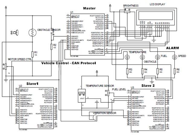
ISSN (Print) : 2320 – 3765
                                                                                           ISSN (Online): 2278 – 8875

      International Journal of Advanced Research in Electrical,
            Electronics and Instrumentation Engineering
                                   (An ISO 3297: 2007 Certified Organization)

                                         Vol. 3, Issue 3, March 2014

with transmission rate of 10 to 125K bps. Others like multimedia systems use medium-speed rate between the previous
two. This approach differentiates various channels and increases the transmission efficiency.
2. CAN Bus for vehicle drive control System
          A typical drive system with the control unit has electronic fuel injection system, automatic transmission
systems, antilock braking system (ABS), airbag systems etc. These units are the core components in a modern car
system. They are sensitive for time and closed to the reliability and security of the entire system. As each control unit
for real-time requirement is based on the data update rate and the control period varies, in order to meet the real-time
requirements of each subsystem, it is necessary to achieve the implementation of public data sharing, such as engine
speed, wheel speed, and throttle pedal location. The contents include the completion of speed measurement, fuel
measurement, A/D conversion, the calculation conditions, the control actuator and a series of processes. That means the
sending and receiving data in 1ms must be completed within the electrical control in order to achieve real-time
requirements. Therefore, the data exchange network must be a priority-based competitive mode, and has a very high
speed communication fashion.
3. CAN Bus for accessories control system
          CAN bus for vehicle system is a leading control network that connects several objects. They are central
controller, 4-gates controller, memory modules and other components. There are several items controlled by the CAN
bus [2]. They are locker, windows, luggage locker, mirrors and interior dome light. In the case of remote control, it
involves the remote control signal receiving and processing the anti-theft and warning systems.

B. Main control module

                                  Fig 2.PROPOSED SYSTEM BLOCK DIAGRAM

1.Peripheral interface controller (PIC)
          PIC is a family of Harvard architecture microcontrollers made by microchip technology of control peripheral
devices, load from main cpu.PIC is equivalent to the automatic nervous system.PIC is very cost effective, and many
types of PIC is available for low cost. There is a chance to choose the PIC for suitable application.PIC execute most of
instruction in 0.2 micro seconds (or) 5-instructions per microseconds. It has up to 12 independent interferences.PIC is
resets by Watchdog timer (WDT).PIC micro controllers has no. Of inbuilt modules like ADC, CAN that increase
versatility of microcontrollers. PIC18F458 has Power-on Reset (POR), Power-up Timer (PWRT)
and Oscillator Start-up Timer (OST) Watchdog Timer (WDT) with its own on-chip RC oscillator Programmable code
protection, Power-saving Sleep mode.

Copyright to IJAREEIE                                    www.ijareeie.com                                        7599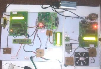
ISSN (Print) : 2320 – 3765
                                                                                             ISSN (Online): 2278 – 8875

      International Journal of Advanced Research in Electrical,
            Electronics and Instrumentation Engineering
                                    (An ISO 3297: 2007 Certified Organization)

                                         Vol. 3, Issue 3, March 2014

                                      Fig 3 .Pin diagram of PIC18F458

2.CAN bus Module Features in PIC18f458:
    a) Complies with ISO CAN Conformance Test
    b) Message bit rates up to 1 Mbps
    c) Conforms to CAN 2.0B Active Spec with:
    d) 29-bit Identifier Fields
    e) 8-byte message length
    f) 3 Transmit Message Buffers with prioritization
    g) 2 Receive Message Buffers
    h) 6 full, 29-bit Acceptance Filters
    i) Prioritization of Acceptance Filters
    j) Multiple Receive Buffers for High Priority
    k) Messages to prevent loss due to overflow
    l) Advanced Error Management Features

C.OTHER ACCESSORIES
1.LIQUID CRYSTAL DISPLAY (LCD)
         A liquid crystal display is a special thin flat panel that can let light go through it, or can block the light.
(Unlike an LED it does not produce its own light). The panel is made up of several blocks, and each block can be in
any shape. Each block is filled with liquid crystals that can be made clear or solid, by changing the electric current to
that block. Liquid crystal displays are often abbreviated LCDs. Liquid crystal displays are often used in battery-
powered devices, such as digital watches, because they use very little electricity. They are also used for flat
screen TV's. They work well by themselves when there is other light around (like in a lit room, or outside in daylight).
The LCD uses technology called electro-optical modulation. This means it uses electricity to change how much light
passes through it.
2.ULTRASONIC SENSORS
         Ultrasonic sensors (also known as transceivers when they both send and receive, but more generally called
transducers) work on a principle similar to radar or sonar which evaluate attributes of a target by interpreting the echoes
from radio or sound waves respectively. Ultrasonic sensors generate high frequency sound waves and evaluate the echo
which is received back by the sensor. Sensors calculate the time interval between sending the signal and receiving the
echo to determine the distance to an object.
3.TEMPERATURE SENSORS (LM-35)
         LM-35 was Calibrated Directly in ° Celsius (Centigrade).It is Linear + 10 mV/°C Scale Factor0.5°C Ensured
Accuracy (at +25°C) .Rated for Full −55°C to +150°C Range. LM-35 is Suitable for Remote Applications. It is Low
Cost Due to Wafer-Level Trimming. It Operates from 4 to 30 V and Less than 60-μA Current Drain .It has Low Self-
Heating 0.08°C in Still Air. And Low Impedance Output, 0.1 Ω for 1 mA Load. It indicates the low level and high level
temperature measurement and automotive ignition level gas exhausting, over heat when vehicle engine/motor speed
was increased gradually.

Copyright to IJAREEIE                                     www.ijareeie.com                                         7600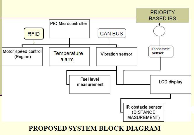
ISSN (Print) : 2320 – 3765
                                                                                         ISSN (Online): 2278 – 8875

      International Journal of Advanced Research in Electrical,
            Electronics and Instrumentation Engineering
                                  (An ISO 3297: 2007 Certified Organization)

                                        Vol. 3, Issue 3, March 2014

4.RFID MODULE
         RFID module- (RFID reader, receiver & transmitter) Vehicle RFID reader. RFID receive & transmitted about
6-8m.Read before viewing distance of such locations that are, for example school zones, speed breakers, hospital
zones, etc., in proposed system. When vehicle reaches particular viewing distance of some critical zones then the RFID
module can read the RFID tag and sends the control signals to the master circuit or engine control unit for braking
process in automatic enabled vehicles. And it monitor the current critical zones in LCD using received signals from
RFID tags& RFID module(RFID receiver & transmitter).

                                          FIG 4.RFID MODULE MODEL
5.ECU Testing

        ECU testing tools from Vector support in broad based implementation of simulation and test environments.
Regardless of task in the development process the Vector test tools provide a scalable and re-usable solution from
pureSiL simulations to HIL testing to functional tests.

 Fig. 5 An ECU mounted directly on a diesel engine of a truck. The arrows indicate the ECU connectors, which are
                                             interfaces to the CAN.

                                         III. SOFTWARE STRUCTURE

       The vehicle control system is programmed using the Embedded C in mikroelectronika for PIC and debugged
with PROTEUS simulation. MP Lab IDE PICkit-3 is used for fusing embedded-c coding with CAN IC-18f458.

Copyright to IJAREEIE                                   www.ijareeie.com                                      7601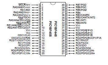
ISSN (Print) : 2320 – 3765
ISSN (Online): 2278 – 8875
International Journal of Advanced Research in Electrical,
Electronics and Instrumentation Engineering
(An ISO 3297: 2007 Certified Organization)
Vol. 3, Issue 3, March 2014
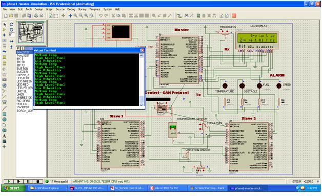
Fig 6.1simulation results of proposed system
Fig 6.2 simulation results of proposed system
Copyright to IJAREEIE www.ijareeie.com 7602
ISSN (Print) : 2320 – 3765
                                                                                          ISSN (Online): 2278 – 8875

      International Journal of Advanced Research in Electrical,
            Electronics and Instrumentation Engineering
                                   (An ISO 3297: 2007 Certified Organization)

                                        Vol. 3, Issue 3, March 2014

                              IV. WORKING MODEL CIRCUITS AND RESULTS

                                  Fig 5. Master circuit& Slave circuit

         Fig 5 shows the circuit diagram of master node. It consists of PIC18f458, Speed detection unit, LCD, Buzzer.
And it shows the slave circuit. This unit consists 2 slave unit named as Slave 1 and Slave 2. Both slave units are
PIC18F4580 controller. Power supply for both slave units and other sensors are 5V DC. Slave 1 unit connected with 2
sensors, Motor speed control sensor, Ultrasonic sensor. This sensor generates analogue signal and send to Slave1
controller. Slave 1 controller converting analogue signal into digital signal, then sends to PIC controller through CAN
MCP2551 controller. Slave 2 unit connected with following units are, Lightning sensor, Ultrasonic obstacle sensor,
Vibration sensor, RFID module.

                                                Fig 7. Working model

Fig 7 shows the working model of vehicle control system using CAN.

Copyright to IJAREEIE                                   www.ijareeie.com                                       7603
ISSN (Print) : 2320 – 3765
ISSN (Online): 2278 – 8875
International Journal of Advanced Research in Electrical,
Electronics and Instrumentation Engineering
(An ISO 3297: 2007 Certified Organization)
Vol. 3, Issue 3, March 2014
Results:
Fig 8. Fuel level low alarm Fig 9. Obstacle detect alarm
Fig 10. Over speed control OK Fig.11,Temperature over alarm
The LCD provided at the driver’s panel displays the various alarms generated with different sensors. Alarm
during the various cases like high pressure in tyres, Fuel level low, Obstacles around the vehicles, Over speed etc.,
V. CONCLUSION
This project introduces an embedded system with a combination of CAN bus systems. Digital control of the
vehicle is an important criterion of modern technology. With the rapid development of embedded technology, high-
performance embedded processor is penetrated into the automotive industry, which is low cost, high reliability and
other features to meet the needs of the modern automobile industry. The proposed high-speed CAN bus system solves
the problem of automotive system applications, also has a certain practical value and significance. With PIC as the
main controller and it makes full use of the high-performance of PIC18f458, high-speed reduction of CAN bus
communication control networks and instrument control. so ,as to achieve full sharing of data between nodes and
enhance their collaborative work. This system features efficient data transfer among different nodes in the practical
applications. And it introduced the distance measurement using ultrasonic sensors. This proposed system provides the
intelligent breaking system using RFID module at automatic braking system enabled vehicles.
Copyright to IJAREEIE www.ijareeie.com 7604ISSN (Print) : 2320 – 3765
ISSN (Online): 2278 – 8875
International Journal of Advanced Research in Electrical,
Electronics and Instrumentation Engineering
(An ISO 3297: 2007 Certified Organization)
Vol. 3, Issue 3, March 2014
REFERENCES
[1] Kumar, M. A.Verma, and A. Srividya, Response-Time “Modeling of Controller Area Network (CAN). Distributed Computing and Networking,
Lecture Notes in Computer Science Volume 5408, p 163-174, 2009.
[2] Tindell, K., A. Burns, and A.J. Wellings, Calculating controller area network (CAN) message response times. Control Engineering Practice, 3(8):
p. 1163-1169, 2005.
[3] Li, M., Design of Embedded Remote Temperature Monitoring System based on Advanced RISC Machine. Electrotechnics Electric, 06, p. 273,
2009.
[4] Prodanov, W., M. Valle, and R. Buzas, A controller area network bus transceiver behavioral model for network design and simulation. IEEE
Transactions on Industrial Electronics, 56(9): p. 3762-377, 2009.
[5] ISO (1993). Road Vehicles: Interchange of Digital Information: Controller Area Network (CAN) for High Speed Communication. ISO
11898:1993.
[6] B.Gmbh, “CAN specification” vol 1 Version 2.0, 1991.
[7] Pazul, “Controller Area Network (CAN) Basics”, Microchip technology Inc., AN713, May 1999.
[8] Wilfried Voss, A comprehensive guide to controller area network, Copperhill Media Corporation, 2005-2008.
[9] Benjamin C Kuo, M. Farid Golnaraghi, Automatic Control systems, Eight edition, John wiley & sons., Inc 2003.
BIOGRAPHY
Author pursuing his under graduate studies in Christ the king engineering college Coimbatore in
2014. And he completed his course of embedded technology at JRM TECHNOLOGIES in
Coimbatore 2014. He published his paper in 1 international conference. His areas of interests are in
the field of automation and Embedded systems. And his plan for future work on creative works on
Implementation of real-time automotive sensor control areas in vehicles with the CAN based
embedded techniques.
Copyright to IJAREEIE www.ijareeie.com 7605You can also read