Visual Inspection of Sterile Products - Best Practices Document - Indian Pharmaceutical ...
←
→
Page content transcription
If your browser does not render page correctly, please read the page content below

Visual Inspection
of Sterile Products
Best Practices Document

CONTENTS
 1.            PREFACE

 2.            INTRODUCTION
                2.1                    PURPOSE               AND   SCOPE
                2.2                    BACKGROUND
                2.2.1                  INSPECTION PROCESS CAPABILITY
                2.2.2                  PATIENT RISK

 3.            INSPECTION PROCESS FLOW
                3.1                    100% INSPECTION
                3.2                    AQL SAMPLING                 AND   TESTING
                3.3                    REMEDIATION                 AND   ALTERNATIVE PRACTICES
                3.3.1                  REINSPECTION
                3.3.2                  TWO-STAGE INSPECTION

 4. INSPECTION LIFECYCLE
                4.1                   EXTRINSIC, INTRINSIC,                OR INHERENT      PARTICLES
                4.2                  CONTROL                AND    PREVENTION      OF   PARTICULATES
                                4.2.1                    ROBUST DESIGN    DURING   DEVELOPMENT
                                4.2.2                    COMMON SOURCES OF INTRINSIC PARTICULATES
                                4.2.3                    FORMULATION COMPONENTS
                                4.2.4                    PACKAGING COMPONENTS
                4.3                   PARTICULATE REMOVAL                   BY   COMPONENT     WASHING
                                4.3.1                    GLASS CONTAINERS
                                4.3.2                    ELASTOMERIC CLOSURES
                                4.3.3                    GLASS HANDLINGS FOR DEPYROGENATION PROCESS
                                4.3.4                    EQUIPMENT PREPARATION FOR STERILIZATION PROCESS
                                4.3.5                    FILLING LINE
                4.4                  TRENDING                OF   VISUAL INSPECTION PROCESS

IPA Sub-Group 4: Visual Inspection of Sterile Products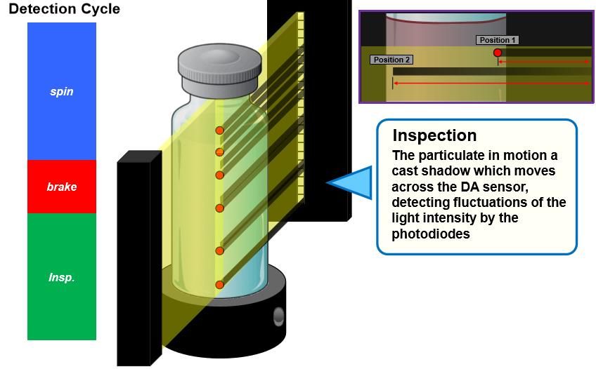
CONTENTS
 5. INTERPRETATION OF VISUAL INSPECTION RESULTS
                5.1                    DEFECT CLASSIFICATION
                5.2                    UNIQUE PRODUCTS                   AND   CONTAINERS CONSIDERATIONS
                                5.2.1                    LYOPHILIZED PRODUCT
                                5.2.2                    P OWDER PRODUCT
                                5.2.3                    E MULSION AND SUSPENSION PRODUCT
                                5.2.4                    A MBER CONTAINERS
                                5.2.5                    T RANSLUCENT PLASTIC CONTAINERS
                                5.2.6                    L ARGE VOLUME CONTAINERS
                                5.2.7                    COMBINATION PRODUCTS
                5.3                    ALTERNATE INSPECTION STRATEGIES                       FOR

                                        SUPPLEMENTAL TESTING
                                5.3.1                    T RANSFER
                                5.3.2                    F ILTRATION
                                5.3.3                    CLARIFICATION
                                5.3.4                    SIEVING

 6. INSPECTION METHODS AND TECHNOLOGIES
                6.1                    MANUAL VISUAL INSPECTION (MVI)
                                6.1.1                    CRITICAL PROCESS PARAMETERS IN MVI
                                6.1.2                    INSPECTOR FATIGUE     AND   ERGONOMIC CONSIDERATIONS
                6.2                    SEMI-AUTOMATED VISUAL INSPECTION
                                6.2.1                    B ASIC PRINCIPLE
                6.3                    AUTOMATED VISUAL INSPECTION
                                6.3.1                    BASIC PRINCIPLE
                                6.3.2                    E QUIPMENT DESIGN
                                6.3.3                    AUTOMATED INSPECTION PROCESS TYPE
                                ❖         SPINNING : THE CONTAINER IS SPUN , WHICH PUSHES THE CONTENTS UP TO
                                          WALL OF THE CONTAINER , LOWERING THE MENISCUS OF SOLUTION INSIDE .

                                6.3.4                    LIGHT OBSCURATION METHODS
                                6.3.5                    IMAGING METHOD

IPA Sub-Group 4: Visual Inspection of Sterile Products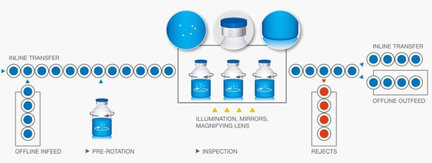
CONTENTS
 7. QUALIFICATION AND VALIDATION OF INSPECTION
    PROCESSES
                7.1                   QUALIFICATION                AND   VALIDATION     OF   MANUAL VISUAL
                                      INSPECTION
                ❖         CANDIDATE SHALL BE AWARDED WITH CERTIFICATION OF QUALIFIED
                          INSPECTOR. LIST OF QUALIFIED VISUAL INSPECTOR SHALL BE
                          PREPARED AND UPDATED. LIST SHALL BE REVIEWED PERIODICALLY TO
                          ENSURE COMPLIANCE .
                                7.1.1                    DISTANCE CRITERIA
                                7.1.2   HOLDING                   OF   CONTAINERS AGAINST WHITE-AND-BLACK
                                BACKGROUND
                                7.1.3                    TOTAL TIME    FOR   VISUAL INSPECTION
                                7.1.4                    LIGHT LUX REQUIREMENT
                                7.1.5                    BRACKETING APPROACH
                                7.1.6                    ENVIRONMENT CONTROL
                                7.1.7                    INITIAL QUALIFICATION
                                7.1.8                    RE-QUALIFICATION
                7.2.1                  VERIFICATION              OF INDIVIDUAL       COMPONENTS: 28
                7.3                    PREPARATION               OF    VISUAL INSPECTION CHALLENGE KIT
                                7.3.1                    P REPARATION OF CONTAINERS FOR QUALIFICATION KIT
                                7.3.2                    CONSTRUCTION AND QUALIFICATION       OF   KIT

 8. QUALIFICATION OF AUTOMATED VISUAL INSPECTION
             (AVI)
 GENERAL INSTRUCTION
                8.1                   PROCEDURE FOR KNAPP KIT PREPARATION                            AND
                                      QUALIFICATION
                8.2                   PROCEDURE                 FOR    QUALIFICATION    OF   AUTOMATIC
                                      MACHINE
                8.3                    PERFORMANCE RUN

 9.            VISUAL INSPECTION OF MEDIA FILL CONTAINERS
IPA Sub-Group 4: Visual Inspection of Sterile Products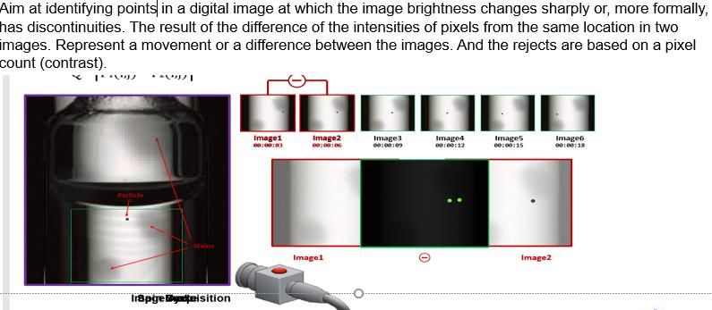
CONTENTS
 10. INSPECTION OF RETAIN/CONTROL SAMPLES

 11. INVESTIGATION CONSIDERATIONS FOR VISIBLE PARTICLES

 12. ANNEXURES

 13. GLOSSARY

 14. REFERENCES

IPA Sub-Group 4: Visual Inspection of Sterile Products
PREFACE
 The IPA launched its Quality Forum (QF) in April 2015 to help Indian pharmaceutical manufacturers to achieve parity with global
 benchmarks in quality. The QF made for commitment to a multi-air journey to address key issues facing the industries and develop
 best practices. McKinsey & Company joined this journey as a knowledge partner.

 In 2020-21, the QF focused on one of the key priority areas: Visual Inspection of Injections for Visible Particles. It took upon itself
 the challenge of establishing robust and seamless visual inspection and process, and release a comprehensive set of guidelines in
 2021.

 The six participating companies in the QF nominated one senior manager each to study the best practice and frame the guidelines.
 They are: Mr. Manikandan Ganesan (Cipla), Mr. Venugopal Gurram (Dr. Reddy’s Laboratories), Mr. Abid Hashmi (Cipla), Mr. Prabu
 Natarajan (Lupin), Mr. Bhavesh Shah (Zydus Cadila) and Mr. Roshan Tathed (IPA). This group is led by Mr. Mustak Sherasia (Sun
 Pharma) and Ms. Ranjana Pathak (Cipla), and Dr. Rajiv Desai (Lupin) was nominated as Mentor.

 The IPA wishes to acknowledge the concerned efforts made by the team over the last twelve months. They shared current
 practices, benchmarked these against existing regulatory guidelines from the USFDA and regulatory agencies such as UK MHRA,
 WHO, etc., developed a robust draft document and had it vetted by a leading subject matter expert. The IPA acknowledges their
 hard work and commitment to Quality.

 The IPA also wishes to acknowledge the CEOs of six member companies who have committed their personal time, human
 resources and funding for this initiative.

 This document is being released at the 6th India Pharmaceutical Forum, to be held by the IPA in Feb 2021 on a virtual platform.
 This will be hosted on the IPA website (www.ipa-india.org) in order to make it accessible to all manufacturers in India and abroad.

IPA Sub-Group 4: Visual Inspection of Sterile Products                                                                                 01
2             Introduction

   2.1             Purpose and Scope
                   ❖      This Best Practices document highlights, and in some instances clarifies, the inspection of injections
                          for visible particles. Particulate matter is defined as “mobile undissolved particles, other than gas
                          bubbles, unintentionally present in the solutions.” Visual inspection is a probabilistic process and the
                          specific detection probability observed for a given product for visible particles will vary with differences
                          in product formulation, particle characteristics, and package design.
                   ❖      The methods discussed in this document are also applicable to the detection of other visible defects
                          that are not the subject of this document, but critical to a qualified and comprehensive inspection
                          process.
                   ❖      This general descriptions provided herein are applicable for the visual inspection activities carried out
                          for different sterile dosage forms, i.e., injectable, ophthalmic products, lyophilized products,
                          suspensions, and media fill containers.

   2.2             Background

   2.2.1            Inspection Process Capability
                   ❖      The desire to detect defects, despite their very low frequency and the randomness of their occurrence,
                          has resulted in the longstanding expectation that each finished unit will be inspected (100%
                          inspection). Although zero defects is the goal and this should drive continuous process improvement,
                          zero defects is not a feasible specification for visible particles given current packaging components,
                          processing capabilities, and the probabilistic nature of the inspection process by manual and
                          automatic machines
                   ❖      Since the detection process is probabilistic, the likelihood of detection is a cumulative function of
                          visible attributes such as particle quantity, size, shape, color, density, and reflectivity.

   2.2.2            Patient Risk
                   ❖      The clinical implications of particulate matter in injections are determined by many factors, including
                          the size and number of particles, the composition of the material, the potential for microbiological
                          contamination, the route of administration, the intended patient population, and the clinical condition
                          of the patient.
                   ❖      The clinical risk to human patients posed by a small numbers of particles is difficult to infer from a
                          consideration of the factors mentioned above, due to the extreme number [RS1] of insoluble particles
                          and the uncontrolled conditions in which they were administered.
                   ❖      The safety considerations related to particulate matter in injections must be assessed for each drug
                          product, intended patient population, and method of administration. No single set of inspection criteria
                          can adequately anticipate all of the potential risks to the patient. The methods should serve as
                          essential requirements when assessing the adequacy of the visual inspection procedure, but
                          alternative acceptance criteria (for example, the use of tightened sampling plans) should be
                          implemented when the patient population and intended use of the product warrant these additional
                          measures.

IPA Sub-Group 4: Visual Inspection of Sterile Products                                                                              02
3 Inspection Process Flow :
3.1 100% Inspection:
❖ Each unit (container closure and its content) of injectable product should be inspected as part of the
routine manufacturing process. This inspection should take place at a point when and where defects
are most easily detected. Each unit may be examined manually with the unaided eye or semi-
automated inspection or light obscuration (LO) or automated inspection.
❖ Manual and semi-automated inspection should only be performed by trained and qualified inspectors.
Inspection may also be enhanced by means of a device that holds more than a single unit at one time
for examination. This inspection may be performed at-line or in-line with filling or packaging or in a
separate, off-line inspection department. The intent of this inspection is the detection and removal of
any observed defect. When in doubt, units should be removed.
Accepted
Units
Acceptance
100%
Filling Sampling and Packaging
Inspection
Testing
Rejected
Units
Analyze and Supplemental
Trend Testing
Rejects
❖ Inspection may be accomplished in a single operation or in multiple steps using a combination of
technologies.
❖ Supplemental testing is required when the nature of the product or container limits visual inspection of
the contents (e.g., with a lyophilized cake or powder, or with an amber glass or opaque container).
❖ Samples for supplemental testing may be taken from any point in the process after 100% inspection.
❖ During 100% inspection, limits on typical rejection rates should be established to identify atypical lots.
These limits may be established for categories of defects (e.g., critical, major, and minor) or for
specific types of defects (e.g., particles).
❖ A review of historical performance is useful in establishing these limits, and the review may include
grouping products similar in appearance and manufacture. Periodic reassessment of these limits is
recommended to account for expected process improvements and/or normal fluctuations in process
baseline.
❖ If a limit is exceeded, it should trigger an investigation. The investigation may include additional
inspection or it may determine whether additional inspection is necessary.
IPA Sub-Group 4: Visual Inspection of Sterile Products 033.2 AQL Sampling and Testing
❖ After 100% inspection, a statistically valid sample is taken from the units accepted by the inspection
process. These sampled units should be manually inspected under controlled conditions by trained
inspectors. The sample should be a representative sample (represents the whole lot).
❖ Tightened sampling plans may be appropriate when an atypical result is observed or reinspection is
performed. These plans specify a sample size for a range of batch sizes and require selection of an
acceptable quality limit (AQL).
❖ The AQL is the defect rate at which 95% of the lots examined will be accepted and is a measure of
falsely rejecting good batches. Critical defects (those that pose the greatest risk to the patient) should
be assigned an AQL with a very low value, that is, zero. Major and minor defects, which pose less risk
to the patient, will have increasing (less stringent) AQL values and accept numbers greater than zero.
Table 1 shows the range of AQL values typically used for visual inspection processes.
Table 1
Typical AQL AccValues for Visual Inspection Processes
Defect Category AQL Range (%)
Critical 0.010–0.10
Major 0.10–0.65
Minor 1.0–4.0
❖ When selecting a sampling plan for AQL testing after 100% inspection using ANSI/ASQ Z1.4, ISO 2859,
or JIS Z9015, it is important to choose the sample size which satisfy the AQL value for the most critical
category (e.g., critical) of defects being evaluated. The accept numbers for this sample size for the
AQL values should be chosen for the other defect categories (e.g., major and minor). This assures that
the sample size will produce a statistically valid result for all defect categories examined.
❖ If the acceptance criteria of the sampling plan are not met, an investigation should be conducted.
Depending on the nature of the failure, this investigation should include forensic
classification/identification of the particle, and examinations of the manufacturing process, the raw
materials, and the packaging materials, as well as the inspection process.
❖ If, after investigation, the inspection process is deemed capable of detecting the defect(s) in question,
the batch may be reinspected. An alternative inspection process that is better suited to detection of a
specific defect may also be chosen for reinspection. After reinspection (performing a second 100%
inspection of the batch), a new AQL sample of the accepted units should be taken and compared
against the established acceptance criteria.
IPA Sub-Group 4: Visual Inspection of Sterile Products 043.3 Remediation and Alternative Practices
3.3.1 REINSPECTION
❖ Reinspection (repeating the 100% inspection followed by acceptance sampling inspection) may be
appropriate if the initial 100% inspection is not successful. This includes instances when the
established 100% inspection failure rate(s) and/or the accept/reject number(s) associated with the
chosen AQL values have been exceeded.
❖ Reinspection should only be conducted using a procedure that has been approved by the Quality
department and addresses key parameters such as the inspection conditions (e.g., same as primary
inspection or modified to enhance detection of a specific type of defect), the number of times
reinspection may be performed (this should be limited and justified), and the acceptance criteria (e.g.,
same as primary inspection or tightened). If reinspection is required often and with repeated reason,
consideration should be given to check appropriateness of CAPA taken and improving the sensitivity of
the primary inspection process or of the manufacturing controls as determined by root cause analysis
3.3.1 TWO-STAGE INSPECTION
❖ In cases where an assignable cause, such as formation of air bubbles or specific container or closure
variation, results in a high false-rejection rate (rejection of acceptable units), the use of a second
inspection step may be considered.
❖ Inspection conditions may be adjusted to provide greater sensitivity in this second inspection step
(e.g., additional inspection time) so as to ensure a high probability that true defective units will be
rejected.
❖ The limitations of the first inspection and the reason for conducting a second stage of inspection
should be clearly defined and documented.
❖ Each inspection stream (those accepted by the first stage and those accepted by the second stage) be
sampled separately and evaluated against the sampling plan acceptance criteria before they are
confirmed as accepted and recombined into a single batch.
Figure 2: Two-stage Inspection Process Flowchart
100% Acceptance
Filling Inspection Sampling and Packaging
(Stage 1) Testing
Accepted
Uncertain Units
Units
Confirming Acceptance
Inspection Sampling and
(Stage 2) Testing
❖ •If a two-stage inspection strategy is used, it must be validated as intended for use. Defective
containers with less than a 100% PoD will have the PoD reduced further with each stage of inspection,
thus the PoD should be determined after inspection through both stages to ensure that acceptable
sensitivity is maintained.
IPA Sub-Group 4: Visual Inspection of Sterile Products 054 INSPECTION LIFECYCLE
4.1 Extrinsic, Intrinsic, or Inherent Particles
❖ Extrinsic Particles: Foreign particles to the manufacturing process are considered to be exogenous or
“extrinsic” in origin; these include hair, non-process related fibers, starch, minerals, insect parts, and
similar inorganic and organic materials. Inclusion of extrinsic material is generally a one-time
occurrence and should result in the rejection of the affected container in which it is seen; however,
elevated levels in the lot may implicate a broader contamination from the same source. These particles
may carry an increased risk of microbiological or extractable contamination, because not much is
known about their path prior to deposition in the product container or their interaction with the
product.
❖ Intrinsic Particles: These are particles within the process, or “inherent”, which are known to be or
intended to be associated with specific product formulations. Any process-related intrinsic particles
should have controls established based on the use of a lifecycle approach such as Defect Prevention.
Another group of particles considered intrinsic is interrelated with the stability of the product. Such
product stability-related particles come from container–closure interaction, changes to the drug
formulation (insoluble degradation products), or temperature sensitivity over time. Stability-related
intrinsic particles should be identified and addressed as early in the product development process as
possible. Particulate formation related with product formulation should be studied in the development
phase and in samples placed on stability to determine the normal characteristics and time-based
changes that can occur.
4.2 Control and Prevention of Particulates
❖ The manufacturing process is designed to keep the final container and its contents clean within the
control parameters established for process-related particulates. Once the container is filled, the
stability of the product needs to be maintained throughout its shelf life. Changes that occur as the
product ages during its normal shelf life must be characterized. Avoidance of intrinsic particle sources
that may affect final product stability depends on careful consideration of the entire product system. If
these intrinsically sourced changes occur, and they affect stability, particles ranging from sub visible to
visible may develop. Typically, these particles result from change mechanisms that slowly affect the
on-shelf product.
4.2.1 Robust Design during Development
❖ To anticipate potential sources of instability that yield intrinsic particles, the product design should be
evaluated from many perspectives, beginning with a literature review of similar formulae/packages.
Points to consider include the reported sensitivities of the active ingredient, the formulation type, and
the final container–closure system needed for delivery. Knowledge of how glass containers are
fabricated, controlled, sterilized, and tested is important as this may affect the tendency to form glass
lamellae as discussed in Evaluation of the Inner Surface Durability of Glass Containers ⟨1660⟩ and
by the FDA (45). Obtaining further information on residual extracts, possible leachates, metals, or
solubility-edge conditions is important as these factors may promote formation of solid material in the
IPA Sub-Group 4: Visual Inspection of Sterile Products 06❖ aging solution. Several additional key factors for successful product design include the product
concentration, solution pH, critical micelle concentration, oligomerization content/potential, package
effects (large surface area, product volume, headspace, light/oxygen transmission), and compatibility
of the formulation with the package. Furthermore, shock/vibration sensitivity at the air/liquid interface
can be a significant contributor to particle formation that requires investigation during product
development. Some key formulation design factors include the formula components chosen and their
purity, the solubilities of the active ingredient(s) and excipients, and consideration of potential salt
forms. Finally, to maximize product stability, it is necessary to consider the final product preparation
for delivery, product dilutions, and shelf stability of the commercial product or its therapeutic
preparations.
❖ To examine the appropriateness of the product design for maintaining product stability, there are two
levels of evaluation. Both levels examine retained containers for visible changes using methods
described in this document, but neither level dwells on low percentage defects.
❖ For the first level of stability study, bench trials consisting of visual inspection of trial containers in the
formulation lab will show general compatibility of the chosen components over time with regard to clarity,
color, and particle formation. Careful product assembly in clean containers, with consideration of the
container type, headspace, and sealing, will yield a beneficial first-pass trial of stability over a period of
several months. Particles will be detected, and the investigation of type is essential in order to
differentiate additive types from instability or package interaction. Pursuit of extrinsic particles at this
stage of development is generally not significant, as the particles do not reflect on the formulation or
manufacturing process that is under development, but rather the manner in which they were filled.
❖ The second, more refined level of stability study involves conducting visual inspections of the injection in
defined, International Council for Harmonization (ICH)-relevant trials (46). This may include periodic
inspection of the same containers over time if the product does not require reconstitution or is not
affected by frequent temperature changes. Detection of minor or subtle differences in these containers is
not the goal at this stage of development. Catastrophic change and the occurrence of intrinsic product-
related visible particles should be the focus. Typically, a set of containers is carefully prepared to exclude
extrinsic particles and is then inspected to cull out any units with visible defects. Next, a numbered set of
containers appropriate for the batch size is placed on trial and visually inspected periodically for changes
due to instability. It is important to be able to analyze the particulate matter or condition (color, haze) in
order to identify the cause of truly stability-indicating events. A typical sample size is 80–100 units. This
should be sufficient for the trial of the package and formulation interaction. Additional sets of containers
stored at selected extremes of ICH temperatures can be followed to aid discovery of solubility-edge
phenomena. When unwanted changes are detected, such as particle formation, solution color change,
solution haze, and package changes, the process of isolation, characterization, and identification can
commence. Identification of the material making up the changes aids in determination of the cause, as
well as development of improvements for future use.
IPA Sub-Group 4: Visual Inspection of Sterile Products 074.2.2 Common sources of intrinsic particulates
❖ Process-related intrinsic particles originating from product contact materials tend to be stable and
unchanging (e.g., glass, rubber, or metal). In contrast, there may also be particles resulting from
product stability-related change mechanisms within the final product. The threshold levels for the
formation of visible change for certain substances may be only 10–100 ppm (0.001%–0.01%) based on
the ability to detect a single 100-μm particle or many sub-10 particles giving a hazy or cloudy
appearance. However, if all of this insoluble material were contained in a single visible particle, it
would likely be cause of rejection of the container.
4.2.3 Formulation Components
❖ The active ingredient may also contribute to the presence of stability-indicating intrinsic particles.
Metal content in the active ingredient has contributed to organometallic salt formation and has also
been observed as precipitated inorganic salts, blooming long after product release. The active
ingredient and related degradation products may also be relatively insoluble and may grow to form
visible particles. The particulate material must be analyzed to determine its chemical nature and
possible identification.
4.2.4 Packaging Components
❖ Extractables and leachables are terms commonly used to describe the potential for primary packaging
materials to contribute unwanted agents to the product. Extractables represent all the materials that
could have contributed, and leachables represent the practical contribution upon contact between
packaging components and drug formulation. These substances can also contribute to the formation of
sub-visible and visible particles.
❖ Formulation attack of the container is a dramatic change and most often occurs in glass container
systems. Glass containers undergo corrosion that is 25 times greater at pH 8 than at pH 4. A
formulation pH above 7, especially with high-ionic strength solutions, promotes attack of the inner
glass surface, resulting in particle generation.
❖ Silicone oil is added to pre-filled glass syringe systems to enhance lubricity for stopper or plunger
insertion and its movement within the syringe barrel. Silicone may also come from tubing used for fluid
transfer and a variety of polymeric fittings and seals that are used in the processing equipment. All of
these components must be compatible with the formulation to minimize leachates. Although silicones
are processed to be sterile and are widely used, their use must still be controlled. Silicone can cause
container sidewall droplets and a variety of visible semi-solid forms. No more than the minimum
quantity should be used during processing. Silicone and other hydrophobic substances have the
capacity to coalesce and agglomerate with other particles, reaching a visible size.
IPA Sub-Group 4: Visual Inspection of Sterile Products 084.3 Particulate Removal by Component Washing
4.3.1 Glass Containers
❖ Each step of the glass-container washing and rinsing process should be evaluated for particle-
reduction capability. The washer validation studies should demonstrate a reduction in naturally
occurring particles or should use seeded containers to demonstrate such reduction capability.
❖ The use of statistical sampling plans with LO and/or membrane microscopic particle-counting method
scan provide a means to demonstrate reduction of both subvisible and visible particles during washing
cycle development and validation. The membrane filtration microscopic method is superior to LO
methods for capturing and characterizing larger foreign particles in the visible range (>100 μm) during
validation or monitoring activities. During process development, validation, and routine use, container-
washing procedures should include periodic visual operational checks. This routine verification
ensures that effective draining of all containers is occurring during all washing and rinsing steps. It is
very important to review the maintenance procedures of the wash-water recirculating filter to ensure
that particle overloading or breakthrough is being prevented.
❖ Glass breakage that occurs during the component washing process could affect surrounding
containers where introduction of glass particle may not be ruled out. The washing cycle should be
evaluated for possible glass particle generation and distribution. Effective, written container-clearance
procedures following these occurrences should specify the number of containers to be removed from
the affected portion of the line. Removing units that could potentially contain glass particles aids in
minimizing particle transfer to the downstream process. It is recommended to perform recording and
trending of glass breakage incidents in order to evaluate the consistency of container washing process.
4.3.2 Elastomeric Closures
❖ Each step of the elastomeric-component washing and rinsing process should be evaluated for particle-
reduction opportunities. Appropriate statistical sampling plans should be utilized to collect meaningful
test units. LO or other automated particle counting and membrane microscopic particle-counting
methods may be used to demonstrate reduction of both sub-visible and visible particles during
washing validation. The membrane filtration microscopic method is superior to LO methods for
capturing and characterizing larger foreign particles in the visible range (>100 μm) during validation or
monitoring activities. During process development and validation and in routine use, container-
washing procedures should include visual checks to ensure that stoppers are not routinely sticking
together. Such sticking surfaces reduce cleaning efficacy and entrap particles.
❖ Ready to Sterilize and Ready to Use components : Periodic assessment of component cleanliness
and washing capabilities of the supplier should be included as part of the supplier qualification
program when using purchased, ready-to sterilize, or ready-to-use components.
❖ Silicon Oil Level : It is recommended that any current siliconization process used, whether in-house or
by the supplier, should be evaluated in order to minimize excess silicone levels while maintaining
machinability of the stoppers. LO or other automated particle-counting method may be used to
compare overall particle level reduction (background silicone oil droplets) during process development
or validation. The level of residual silicone oil will affect the particulate quality of the final filled
product, observed as dispersed droplets and particle-forming matrices.
IPA Sub-Group 4: Visual Inspection of Sterile Products 094.3.3 Glass Handlings for Depyrogenation Process
❖ Processes that use racks or trays for transporting and holding samples, as are typically used in batch
ovens, should be monitored for metal particle generation. The racks or trays should have a formal
maintenance program associated with their routine use. Trays should be inspected for wear and
scoring, which can be sources of particulates. Periodic cleaning, polishing, and/or resurfacing may be
warranted to effectively control particles. Tunnels used for depyrogenation should also have a routine
maintenance program for periodic cleaning, inspection, and replacement of parts that may wear and
generate particles. Routine process observation for glass breakage allows for clearance of any
potentially affected surrounding containers and minimizes the occurrence of glass particles being
carried downstream to filling. Glass-to-glass and glass-to-metal contact should be minimized where
possible to reduce weakening of the glass surface with increased risk of subsequent fracture. The use
of polymeric facing on guides can help in reducing such damage.
4.3.4 Equipment Preparation for Sterilization Process
❖ It is important to minimize redeposition of particles on product contact surfaces after cleaning.
Cleaned and sterilized equipment should be protected by HEPA-filtered, unidirectional airflow until
transferred to, and installed on, the filling line. For cleaned equipment that needs to be wrapped or
bagged prior to sterilization, low-shedding, noncellulose (synthetic) wrapping materials should be
utilized. Cellulose fibers are one of the most common particles found in the injections-manufacturing
environment and injectable products, and their origin will be a prime concern. Final wrapping can be
performed in a grade A environment.
❖ Personnel are a concern for introduction of extrinsic particle types such as eyebrows, eyelashes, facial
hair, and skin cells. The equipment preparation staff should be adequately gowned with hair covers,
facial hair covers, and goggles to prevent contaminating cleaned process equipment.
❖ During validation and monitoring activities of clean- and/or steam-in-place (CIP-SIP) systems
(vessels, filters, tubing, and other product contact equipment), foreign particle burden should be
evaluated after cleaning.
4.3.5 Filling Line
❖ The transfer of open containers should be evaluated and reviewed to mitigate particle contamination.
For example, for aseptically filled products, the transfer should be conducted in Grade A (ISO 5, Class
100), unidirectional air flow to minimize particle contamination. The air in critical zones should be
monitored continuously during operation to confirm compliance.
❖ Routine checks to detect particles and potential particle-generation locations should be explained in
the procedures. Effective, written container-clearance procedures to be used after glass breakage
should specify the number of containers to be removed from the affected portion of the line. It should
be noted that improper set-up and adjustment of the filler can lead to “needle strikes” where the filling
needles make contact with the container being filled. This can generate either stainless steel or glass
particles.
IPA Sub-Group 4: Visual Inspection of Sterile Products 10❖ Filling pump design and the pump's compatibility with the filling solution are important considerations.
Metal-on-metal piston pumps have a greater potential for generating metal particles, compared with
other types of piston pumps. Pump maintenance is essential and includes a requirement to resurface
the cylinders and pistons periodically. Peristaltic-action pumps must be monitored for generation of
silicone tubing particles, especially with aggressive, near-saturated solutions or suspensions. Friction in
the peristaltic roller area can break down the tubing, resulting in the generation of particles (spallation).
Overheated silicon tubing may get hardened and can generate particles.
❖ Stopper bowl surfaces should have a formal maintenance program, and stopper handling or
replenishment by operators should be specifically designed to minimize particle transfer to the
stoppers. Proper operator positioning and avoidance of open containers is important in good aseptic-
filling practices to avoid microbial contamination. Usage of oRABS/Isolator would be a better practice.
These same principles help reduce particle transfer to the open containers and exposed elastomeric
closures.
❖ •Careful selection of cleaning and gowning materials will help reduce contamination from extrinsic
particles and fibers. These clean-room materials should be selected for their superior non-shedding
and low-particle properties.
4.4 Trending of Visual Inspection process
❖ Data obtained from the in-process 100% inspection followed by AQL inspection are used for batch
release. A continuous process verification program with statistical evaluation against pre-established
alert and action limit of each batch prior to release of the batches is a very helpful tool. Both 100% and
AQL inspection data should also be analyzed for adverse trends on a periodic basis, typically at least
annually. Data from the 100% inspection provides the best source of typical defect types and rates
during normal production. High-volume products may generate sufficient data to allow quarterly
analysis, whereas a longer period of time may be necessary to accumulate data for products that are
produced infrequently. Data from component inspection, production 100% inspection, and the AQL
inspections should be evaluated based upon sound statistical principles to determine whether the
current action levels are accurately reflecting the current process capability. Alert and/or action levels
may be established and/or adjusted if the statistical analyses indicate that lower defect levels are
being observed consistently.
❖ When establishing new action or alert levels, a preliminary value may be used until sufficient
production experience is obtained. A minimum of data for 20 lots is usually sufficient to establish the
alert and action limit. Consideration should be given to planned improvements in the manufacturing
and inspection processes. If significant improvements are planned, the reduction of the action/alert
level should not be instituted until the impact of the improvement is measured over sufficient time to
establish the validity of the new value.
IPA Sub-Group 4: Visual Inspection of Sterile Products 115 Interpretation of Visual Inspection Results
5.1 Defect Classification
❖ Defects are commonly grouped into classifications based on patient and compliance risks. The most
common system uses three groups: critical, major, and minor.
Critical Defects
❖ Critical defects are those that may cause serious adverse reaction or death of the patient if the
product is used. This classification includes any nonconformity that compromises the integrity of the
container and thereby risks microbiological contamination of the sterile product.
Major defects
❖ Major defects carry the risk of a temporary impairment or medically reversible reaction, or involve a
remote probability of a serious adverse reaction. This classification is also assigned to any defect
which causes impairment to the use of the product. These may result in a malfunction that makes the
product unusable.
Minor defects
❖ Minor defects do not impact product performance or compliance; they are often cosmetic in nature,
affecting only product appearance or pharmaceutical elegance.
5.2 Unique Products and Containers Considerations
5.2.1 Lyophilized Product
❖ Lyophilized products receive 100% inspection after the freeze-drying step is completed and each unit
has been sealed. However, the solid, lyophilized cake can mask the presence of visible particles
because they cannot be seen within the solid matrix. The cake surface is visible during inspection but
accounts for only a small fraction of the cake volume. Because of these challenges in evaluating
acceptability, a representative sample of the lot is to be selected and reconstituted and inspected for
visible particles in addition to 100% inspection of the cakes for visible particles. Care must be taken
during reconstitution of these samples to avoid contamination that can lead to false-positive results.
Filtered WFI or Diluent (which is to be used for reconstitution) should be filtered before use by using a
0.2 micron filter. Sample preparation should be done in a clean environment with appropriate particle-
control measures. Reconstituted samples should be inspected using the same conditions as those for
visible particles. The destructive nature of this test limits the size of the sample; however, the resultant
fluid allows visible particles to be more readily detected. Typical sampling plans for this type of test
can be found in the special sampling plans S-3 and S-4 in ANSI/ASQ Z1.4.
IPA Sub-Group 4: Visual Inspection of Sterile Products 12❖ The S-plans offer a practical compromise between sample size and statistical power and for most
batch sizes between 3,201 and 150,000 suggest a sample size of 20 with an accept number of 0 (based
on an AQL of 0.65%). Sample sizes larger than 20, as found in these sampling plans, may be
appropriate for larger batch sizes when additional sensitivity is desired. Alternative plans are
acceptable, but care should be taken to examine the UQL of such plans in order to assess their
sensitivity. Once inspection of these reconstituted samples has been performed, they may be used for
other required testing, such as that for subvisible particles, potency, impurities, or other specified
tests. If particles are detected in this relatively small sample, additional units may be reconstituted as
part of an investigation and to assess the compliance of the entire batch. The size of the additional
sample should be based on the total sample size (initial plus additional sample) required to have an
accept number greater than 0 for a sampling plan with an AQL of 0.65% or less. This will be based on
the batch size. The results from the samples must be combined, rather than resampling and basing the
accept decision on the results of the second sample only.
❖ Alternatives to reconstitution can be considered, such as collection of lyophilized samples from the
filling line after stopper insertion. Such samples represent the majority of particle exposure risk. These
risks should be assessed and documented to justify this approach.
❖ Filling line performance can be evaluated by performing water run/liquid products filled in same filling
line used for lyophilized product.
5.2.2 Powder Product
❖ Sterile powders are difficult to inspect for particles due to powder flow and the occlusion of white or
light-colored particles by the drug product itself. Sterile powders should be reconstituted and
inspected for visible foreign particles using an approach similar to that for lyophilized products, as
discussed above.
5.2.3 Emulsion and Suspension Product
❖ The manufacturer may allow inherent particles if the product is an emulsion or suspension. For
suspension products, a test dissolving the suspension or disruption of the emulsion that provides for
extrinsic and intrinsic particle detection is also recommended as part of destructive supplemental
testing of a small sample as described above for lyophilized products.
5.2.4 Amber Containers
❖ Inspecting amber containers is challenging because selected elements have been added to mask UV
light penetration into the Type I glass container. Light transmission is blocked below 500 nm, and thus
increased light intensity (e.g., 8,000 – 10,000 lux) may be required to observe visible particles during
inspection. Directional lighting from behind the container may also be beneficial. At the extreme, filled
solution in practically opaque containers may be audited via sampling and transferred to clear, clean
containers. The membrane filtration microscopic method is also suitable for capturing and
characterizing larger foreign particles in the visible range (>100 μm).
IPA Sub-Group 4: Visual Inspection of Sterile Products 135.2.5 Translucent Plastic Containers
❖ Translucent plastic containers are chosen for break resistance or other properties that glass cannot
offer, such as injection molding into shapes that minimize hold-up volume or for use in a combination
product. Plastic containers may have optical properties that require significantly more light (e.g.,
8,000–10,000 lux) to illuminate any visible particles against black and white backgrounds. Directional
lighting from behind the container may also be beneficial.
5.2.6 Large Volume Containers
❖ Large-volume containers (>100 mL) may require additional time to complete a thorough inspection.
For flexible bags, the semi-transparent nature of the PVC film used to manufacture these containers
may require the use of additional light intensity to enhance the visibility of particles. Directional
lighting from behind the container may also be beneficial. PVC containers may have optical properties
that require significantly more light (e.g., 8,000–10,000 lux) to illuminate any visible particles against
black and white backgrounds.
5.2.7 Combination Products
❖ When inspecting the unlabeled primary drug container for a combination product, the inspection
considerations should be the same as those specified for a conventional drug product in a vial or
syringe. This inspection should be performed before assembly into the device. Where there are critical
attributes that are only visible after assembly (such as alignment with a fill-level window), a second
inspection after assembly may also be required.
5.3 Alternate Inspection Strategies for Supplemental Testing
5.3.1 Transfer
❖ When the container limits thorough inspection, transfer to a clear and readily inspectable container is
recommended. Using verified clean and verified clear containers, the sample is opened and drained to
the receiving container, plugged, and then visually inspected.
5.3.2 Filtration
❖ Membrane filtration methods, such as in Particulate Matter in Injections, Method 2 Microscopic
Particle Count Test, collect all solid particles from the fill onto a membrane. Samples may be individual
or pooled for analysis. This method will reveal all solid particles (visible and subvisible), which may be
sized microscopically, and permits qualitative categorization of these retained solids.
5.3.3 Clarification
❖ In the case of suspensions, there is a wide range of active ingredient particle sizes, from nano–sized
(5.3.4 Sieving
❖ If the solid particle suspension is small enough to allow selective sieving, this may be used as an
alternative to membrane filtration. The very small solids pass through the sieve and larger (>100 μm)
particles are retained, counted, and categorized.
IPA Sub-Group 4: Visual Inspection of Sterile Products 156 Inspection Methods and Technologies
6.1 Manual Visual Inspection (MVI)
❖ Manual visual inspection (MVI) is the reference inspection method described in all of the major
pharmacopoeias. It consists of viewing filled and sealed containers under controlled conditions. This
process may be aided by the use of a tool to allow consistent examination of more than one container
at a time. The quality decision, to either accept or reject the container, is made by a trained person.
Inspection is a probabilistic process and detection rates❖ Time spent per container may be controlled through the use of a pacing device such as a light or tone.
Recording the time spent inspecting each batch and then calculating a nominal inspection rate is a good
way to confirm that the rate of inspection was within established limits. Correction can be made for
non-inspection activities performed during this time by the inspectors to better document the nominal
inspection rate.
❖ Container handling and movement : Good techniques for manual inspection include a careful swirl or
inversion of the liquid product within the container. This displaces any particles from the upper inner
surfaces of the container and the closure and puts them into motion. A technique that minimizes the
introduction of air bubbles is important, as air bubbles can appear as particles and interfere with
detection of offending particles. Holding many containers by hand at once should be avoided. Container
motion or rotation is also helpful for identifying small container defects such as cracks or chips.
Following table provide guidance for recommended quantity to be inspected at a time
Container Size Containers to be checked at a time
1-2 ml Not More Than 6
3-5 ml Not More Than 6
06-15 ml Not More Than 5
16-25 ml Not More Than 4
26-30 ml Not More Than 3
31-50 ml Not More Than 2
51-100 ml and more Not More Than 1
❖ Magnification : Some inspection processes use a large magnifier to increase image size and thus
increase the probability of detecting and rejecting containers with defects near the threshold of
detection. Although magnification can be useful for critical examination of a portion of the container, it
does not often lead to increased overall detection rates for defects of interest. This may be due, in part,
to the added eye strain that often results from the use of magnification. Although not recommended for
use during routine inspections, magnification can be helpful for critical examination of a small number
of units, as may be needed during an investigation.
IPA Sub-Group 4: Visual Inspection of Sterile Products 176.1.2 Inspector Fatigue and Ergonomic Considerations
❖ Inspecting for extended periods of time can cause inspector fatigue and a decrease in inspection
performance. It is recommended that inspectors be given a break from performing inspection at least
every hour. This break should allow time to rest the eyes and mind, and may be achieved with a short
rest (e.g., 10 min/hour) or a longer meal break. This need for regular breaks may also be met through
rotation to a non-inspection function, such as material handling or documentation.
❖ Inspection stations should be designed and operated in a manner that minimizes the inspector's risk of
repetitive-motion injury. Adjustable chairs and careful positioning of light sources as well as incoming
and inspected product can reduce the risk of such injury. These adjustments can also reduce inspector
fatigue and discomfort, both of which can be distracting and thus can decrease.
❖ Temperature and humidity should be controlled in inspection room. Reduced ambient lighting is
recommended in order to focus the inspection process and to reduce distraction from extraneous
reflections. Special care should be given to inspection rooms with exterior windows that allow daylight
into the room and thus changing ambient lighting throughout the day and with changing seasons.
6.2 Semi-Automated Visual Inspection
❖ Semi-automated visual inspection combines automated material handling of the containers to be
inspected with human vision and judgment to make the decision to accept or reject. These systems
often use a conveyor equipped with rollers to transport the containers in front of the inspector inside
an inspection booth or station.
❖ These systems offer a means of controlling the presentation of the vials and can offer additional
lighting options, such as Tyndall lighting, which may enhance the appearance of some defects such as
cracks or small particles.
❖ Mirrors may also be used to provide a clear view of the top and bottom of each container. Rejected
units may be removed from the rollers by hand, and some systems are equipped with a remote
rejection system that can be triggered by the inspector.
❖ Care should be taken in the qualification and operation of these systems to ensure full rotation of vials
in the inspection zone; this allows examination of all surfaces. In addition, studies should be
conducted to ensure the detection of heavy particles, which may not be lifted from the bottom of the
container, and to ensure that the rate of inspection produces an acceptable detection rate for defects
of interest.
6.2.1 Basic Principle
❖ As mentioned earlier, SAVI combines automated handling of the containers to be inspected with
human vision and judgment to make the decision to accept or reject the container.
❖ As per the Tyndall principle, the contrast of foreign particle is intensively enhanced under the strong
light beam and the container can be inspected very quickly.
IPA Sub-Group 4: Visual Inspection of Sterile Products 186.2.2 Equipment Design
A semi-automated visual inspection system comprises:
a) Infeed conveyors with rollers to transport the containers in front of the inspector inside an inspection
booth or station.
Inspection booths equipped with additional lighting system, with or without magnification, which
enhance the appearance of some defects such as cracks and small particles. High-speed spin stations
or rollers are fitted in the machine to set particles in motion by rotating the containers in front of
inspectors as they pass through the inspection zone. In addition, mirrors may also be used to provide a
clear view of the top and bottom of each container.
b) Rejection system equipped with a remote rejection arrangement that can be triggered by the inspector,
or rejected units may be removed from the rollers by hand.
c) Outfeed conveyors to transport the containers to collection of inspected units for further processing.
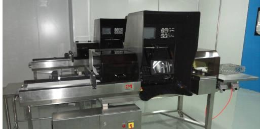
IMAGE OF A TYPICAL SEMI-AUTOMATIC INSPECTION MACHINE
SCHEMATIC REPRESENTATION OF SEMI-AUTOMATED INSPECTION PROCESS
IPA Sub-Group 4: Visual Inspection of Sterile Products 196.2.3 Critical Process Parameters for Semi-automated Visual Inspection System
Following are the critical process parameters to be taken care during qualification and operation:
a) Light intensity must be controlled as with manual visual inspection to allow for detection of
particulate suspended in liquid as well as other defects like cracks, abnormal sealing, etc.
b) Rate of inspection is controlled by the speed of the infeed conveyor/rollers to produce an acceptable
detection rate for defects of interest.
c) Spin speed for the liquid products and rotation rate of containers to ensure full rotation of vials in the
inspection zone; this allows examination of all surfaces. Spin speed for liquid products and rotation
rate for all containers should be established during validation/qualification and maintained within the
validated range for routine inspection
6.3 Automated Visual Inspection
❖ Automated visual inspection (AVI) combines automated material handling of the containers with
electronic sensing of product appearance. Containers that do not meet pre-programmed acceptance
criteria are automatically rejected by the machine. Multiple cameras are used to image various regions
on the container in great detail.
❖ A defect found by any camera is tracked through the machine to allow accurate ejection by the rejection
system. These machines also offer detailed reporting of defects observed in a specific production lot.
❖ Validation of the automated inspection equipment should be based on comparison with the compendial
manual inspection process with an expectation that alternative inspection methods demonstrate
equivalent or better performance. Significant effort is required to program these systems and to test
their performance against a range of known defects, as well as acceptable containers.
6.3.1 Basic Principle
❖ As mentioned earlier, an Automated Visual Inspection (AVI) machine acquires a sequences of images of
product appearance by electronic sensing, processes them according to parameter setting of recipe
(pre-programmed acceptance criteria), and provides inspected results as ‘accepted’ or ‘rejected’
automatically.
6.3.2 Equipment Design
An automated inspection system comprises:
a) Vision system with multiple cameras in order to image various regions on the container in great detail.
Cameras are connected to processing boards of the machine which track defect detection and allow
accurate ejection by the rejection system.
IPA Sub-Group 4: Visual Inspection of Sterile Products 20b) Illumination system by which lighting from bottom, sides, and polarized lighting is provided, depending
on the type of defect to be detected. Each camera is coupled with unique lighting which highlights
specific defects in the region of interest.
c) Spinning system for rotation of container/the liquid with a view to “move” possible objects inside the
liquid before inspection.
6.3.3 Automated inspection Process Type:
6.3.3.1 Light Obscuration Methods (static division detection)
Light obscuration method comprise of following steps:
❖ Spinning: the container is spun, which pushes the contents up to wall of the container, lowering the
meniscus of solution inside.
❖ Break on: the container is brought to an abrupt halt, forcing the particulate matter into motion.
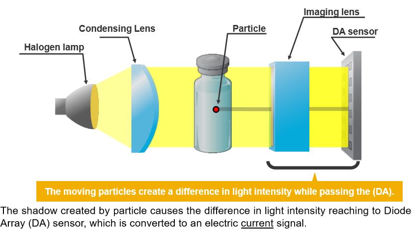
❖ Inspection: the particulate in motion casts shadows which move across the Diode Array (DA) sensor
which detects the fluctuation of light intensity which then is converted to an electric current signal.
SCHEMATIC REPRESENTATION OF LIGHT OBSCURATION PRINCIPLE IN
AUTOMATED INSPECTION PROCESS
IPA Sub-Group 4: Visual Inspection of Sterile Products 21DIAGRAMMATIC REPRESENTATION OF DETECTION CYCLE OF LIGHT
OBSCURATION PRINCIPLE IN AUTOMATED INSPECTION PROCESS
6.3.3.2 Imaging Methods (camera inspection detection)
Imaging methods comprises the following steps:
❖ Image capture: high-resolution digital images of containers under inspection are acquired by the digital
cameras.
❖ Image processing: the acquired digital images are processed by high-speed processors by dividing into
inspection windows, and a collection of tools such as image subtraction, pixel counting, intensity
analysis, and others are used to assess the images against programmed quality attributes.
DIAGRAMMATIC
REPRESENTATION OF
DETECTION CYCLE OF
IMAGE METHOD PRINCIPLE
IN AUTOMATED INSPECTION
PROCESS
IPA Sub-Group 4: Visual Inspection of Sterile Products 226.3.4 Light Obscuration Methods
❖ LO methods are optimized for sensitivity to moving particles, and can thus be made less sensitive to
minor container imperfections. These methods can be used with both tubing and molded containers.
Results are generally robust in detecting single particles that are 100 μm in diameter and larger,
though detection of smaller particles at or below the visible threshold is improved when multiple
particles are present.
❖ These systems can also detect fill height by detecting the shadow of the solution meniscus. Generally,
this process is not sensitive enough to ensure compliance with dose or fill-weight specifications, but it
can provide a secondary check of gross fill. Sensitivity is a function of the container shape, with greater
sensitivity being achieved in small-diameter containers.
6.3.5 Imaging Methods
❖ Imaging systems can detect particles and fill level, as well as other container and closure attributes.
Inspection in this manner can provide comprehensive inspection of visual attributes. These systems can
offer high sensitivity, but may also have high false rejection rates if container and product attributes are
not tightly controlled. These technologies may be used alone or in combination with other inspection
methods to provide a comprehensive assessment of product quality before labeling and packaging. X-
ray imaging has also been explored as a means of detecting particles within freeze-dried cakes,
powders, or suspensions.
IPA Sub-Group 4: Visual Inspection of Sterile Products 23You can also read


