Viva3D Real-time Stereo Vision - Stereo conversion & depth determination with mixed 3D graphics - ViewPoint 3D Software
←
→
Page content transcription
If your browser does not render page correctly, please read the page content below
Copyright © 2016 ViewPoint 3D                                                            Viva3D Stereo Vision Processing - User Manual

                                       Viva3D Real-time Stereo Vision
                                Stereo conversion & depth determination with mixed 3D graphics
                                                   Project leader: Robin C. Colclough.
                                                              Release 1.31
                                                    Copyright © 2016 ViewPoint 3D

Document: DM-06-120-021                                                                                                            1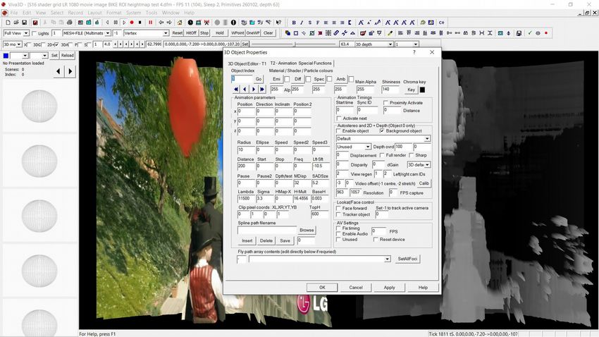
Copyright © 2016 ViewPoint 3D                                                                                            Viva3D Stereo Vision Processing - User Manual

Introduction
Viva3D is an high-performance 3D application that uses 3rd and 4th generation GPUs to provide 3D rendering and image processing in real-time.
Stereo matching performance with 640x480 images on off-the-shelf AMD A10 APUs achieves over 70 FPS, and 30 FPS with HD stereo images. On Intel Atom x5-
Z8300 processors over 12 FPS can currently be achieved with 640x480 stereo images.
This document provides an overview of the facilities of Viva3D and basic settings when used with external stereo cameras, images and side-by-side videos.

Chapter 1 - Principles of Stereo matching
Stereo matching involves the comparison of left and right images of a scene, comparing the horizontal shift between identifiable objects (disparity) to determine depth.
This is a complex process due to a number of issues, such as camera distortion and alignment, pixel noise, lighting, reflections, image complexity and camera focus.

Camera focus: Stereo cameras have unique requirements in regards to focusing due to the need to compare left and right images.

In Fig1 and 2 we see two focus methods, infinity and at point, or “toed-in”.
Scene objects must appear in both images to allow depth determination.

As we can see in Fig 1, focusing on infinity reduces the stereo area, or
“window”, considerably, although allowing great depth range.
Focusing at a point, or towed-in, allows a maximum area of interest to be
processed, but limits the range of depth to a fixed zone. This is the format
commonly used in robotic or medical inspection applications.
To achieve a greater range of depth, both cameras would need to be
mechanically adjusted to the required focal point.

Lateral displacement and Parallax:
Spatial depth within the scene produces a lateral displacement of the two
corresponding points in the left and right stereo images. For close objects
this displacement is larger, and smaller for more distant objects.

Maximum parallax/deviation and depth field (1/30th Rule):
The difference between the largest displacement (produced by the 'closest object') and the smallest (produced by the 'most distant object') is called the displacement
deviation or maximum parallax. In general, the deviation should not exceed 1/30 of the entire image width. With the 4:3 image format of 640x480 resolution, the
deviation is 640/30 = 21 pixels. As can be seen in Fig 2, some image boundary loss occurs due to camera overlap, and in addition, when the deviation, or parallax
exceeds 1/30 of image width, considerable border area is lost.

Document: DM-06-120-021                                                                                                                                                  2
Copyright © 2016 ViewPoint 3D                                                                                            Viva3D Stereo Vision Processing - User Manual

Interocular distance (interaxial separation between cameras) and depth field:
The native parallax for a given screen size simply refers to what percentage of screen width will equal the human interocular. If you are using 2.5 inches as the baseline
interocular and you know your presentation screen will be 38 inches wide (screen sizes are measured diagonally, so a 38” width relates to 42” monitor), then we divide
2.5 by 38. 2.5 ÷ 38 = 0.066 or 7% Therefore the Native Parallax of a 42” screen is 7%, therefore we must keep our maximum positive parallax under 7% of screen
width if we plan to use a 42” screen. If we shoot for a 65” 3DTV, then the calculation is 2.50 ÷ 58 = 0.043, giving a 4.3 % positive parallax.

The 1/30th Rule and distance to nearest object:
The 1/30 rule is a commonly accepted rule that has been used for decades by stereographers. It states that the interaxial separation should only be 1/30th of the distance
from your camera to the closest subject. In the case of ortho-stereoscopic shooting that would mean your cameras should only be 2.5” apart and your closest subject
should never be any closer than 75 inches (about 6 feet) away.

Interaxial x 30 = minimum object distance
 or
Minimum object distance ÷ 30 = Interaxial

Stereo Side-by-Side Camera Rig:
Using two standard 3” wide camcorders in a side-by-side stereo camera rig, the calculation will be 3” x 30 = 90 inches or 7.5 feet to nearest object!

Miniature Boroscope Stereo Camera Rig – for close focus working:
In our miniature stereo camera rig, comprised of two 6mm diameter boroscopes, aligned to focus at
a fixed point (toe-in), we have a 6mm interocular distance, giving 6mm x 30 = 180mm, or 18 cm
focal point.
If we move much beyond these limits, the minimum and maximum parallax ranges generate an
inadequate range for depth calculation in the scene area of interest.
By fine tuning the Stereo video processing module parameters in Viva3D, we managed to achieve
good depth results at 12-36 cm.
To reduce this to 6cm, we would need a 3mm interocular distance, i.e. 3mm cameras.
Boroscope cameras are readily available at low cost, however the manual focus models are
generally unsuitable for stereo camera rigs as focus is achieved via a cable, which is subject to
change at the slightest movement of the boroscope tube.
To control this, we had to mount the cameras on a wooden batten.
A professional miniature stereo camera assembly would require sensors mounted on a solid
substrate aligned for toed-in focus, or an electromechanical arrangement for varied focal point.

Document: DM-06-120-021                                                                                                                                                3
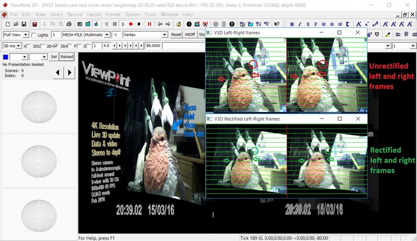
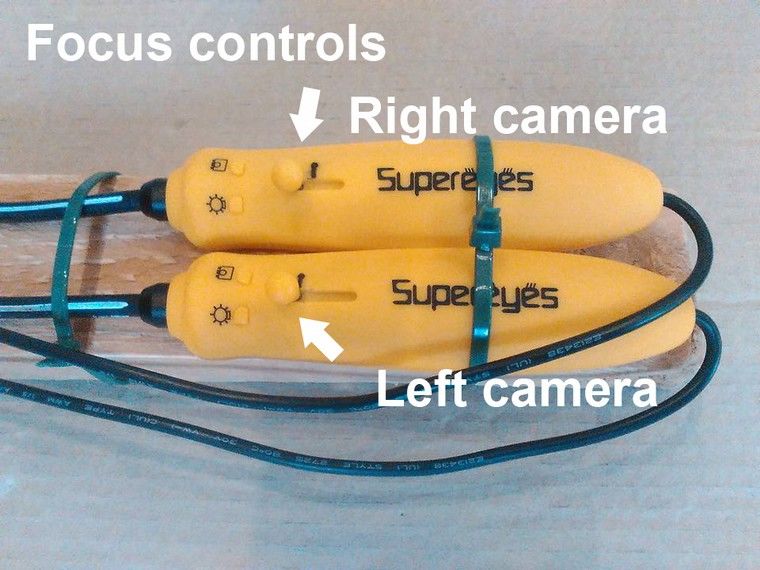
Copyright © 2016 ViewPoint 3D                                                                             Viva3D Stereo Vision Processing - User Manual

Geometric correction and Rectification:
Stereo matching algorithms require image scan-line
alignment as they use block matching algorithms to match
image details. Typical algorithms use Sum of Square
Difference (SSD) or Sum of Square Distance (SAD) to
match pixel blocks.
It is necessary to match averaged-blocks of pixels rather than
individual pixels to avoid pixel noise/variation.
Camera lenses introduce geometric distortion that may vary
from camera to camera. In addition, mounting of camera
sensors and assemblies lead to misalignment of scan-lines
between images largely due to rotation.

In Fig 4 we can see unrectified left and right images, and the
same images below, after correction.
Viva3D uses two external files, one providing intrinsic
camera parameters, focal length, optical centres, etc., and the
other providing extrinsic parameters, such as rotation and
translation vectors for each individual camera. We provide a      Fig 4
utility application to allow users to calibrate their own
cameras, which usually takes around an hour to complete
once a suitable calibration rig has been constructed.

Focusing:
Fig 5 shows the boroscope control handles, mounted on a wooden batten to prevent defocusing
which occurs when the boroscope tubes are moved. Manual focus boroscopes are useful for
camera set-up experimentation, but are not suitable for practical use due to the focus design.

Focusing set-up with Viva3D:
With the boroscope USB connectors connected to the computer, run Viva3D and load the “Fast
Stereo cam test...dfm” form.

Double-click in the camera image and the object editor should appear. Click on Tab2, and enter
the value -1 in Dpth/Test entry box (middle-left of dialog). Click OK, and the alignment window
will be displayed, showing the left and right camera images. Note: If you cannot see the V3D
Rectified images window, press Alt+Tab as it may need to be given focus on Windows systems.       Fig 5

Document: DM-06-120-021                                                                                                                             4
Copyright © 2016 ViewPoint 3D Viva3D Stereo Vision Processing - User Manual
Focusing (continued):
During shipment of the boroscope camera rig it is probable that the focus will have
changed. Hopefully the head mount will have retained the alignment of the camera sensors,
but if not, then re-alignment will be required.
Once you have the camera set-up and focused on a scene with objects placed at 14-24 cm
from the camera, with the Dpth/Test value set to -1 (see fig 6 right) to display the
Rectification window, you can check to see if the objects align across both images. See
Fig 4 for details of alignment window.
If the images are not perfectly aligned, adjust the focus controls of both cameras until the
images are in focus and the lines aligned, see Fig 5 for application interface view.
Re-alignment:
If objects within the left and right images do not align using the focus controls, then
manually rotation of one camera may be required. This procedure should be undertaken
with great care. The mounting screws in the head assembly should allow limited
correction using suitable pliers without the need to adjust the screws.
*Set -1 here
If alignment is completely lost, then manually realigning the cameras is a painstaking
business.
Stereo rectification object overview
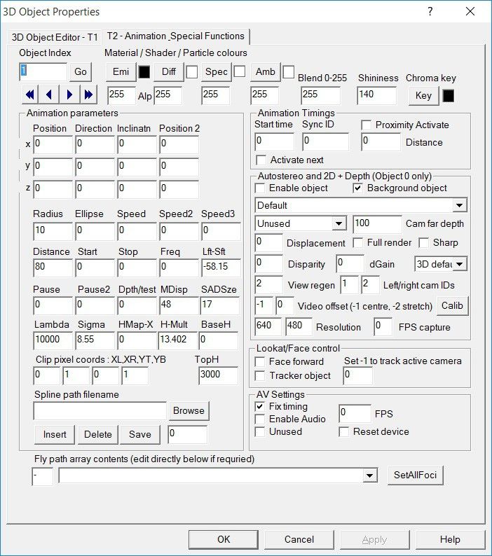
In fig 6 right, we can see the T2 tab of the Viva3D object editor. Every item in the
displayed scene is an object with a unique index. Index 0 is the primary 3D camera for the
scene, although other objects can also be cameras. Do not confuse the 3D camera with the
external cameras; 3D rendering requires a camera object within the 3D world-space.
In the “Fast Stereo cam test...dfm” form, the external cameras are displayed by the object
at index 1. Any object can display an external camera, including the 3D main camera Fig 6
itself, which then operates as both 3D world-space camera, and the object that displays the
external camera direct to the scene's background, in which case the camera display is fixed to the entire screen display, rather than displayed on the mesh surface.
Two modes for external camera display – direct to screen background, or to 3D object space:
When object 0 is used to display the external camera, then the camera left image is rendered to the entire left-side of the 3D backbuffer, and the depth map is rendered
to the right-side of the back-buffer; this is compatible with 3D glasses-free monitors using a right-side depth map, such as Dimenco.
When any other object is used to display the camera, then that object requires a high-resolution mesh to be selected that will be height modulated by the generated
depth map, in a process called depth modulated convergent radial projection(DM-CRP), developed by the ViewPoint 3D team.
Document: DM-06-120-021 5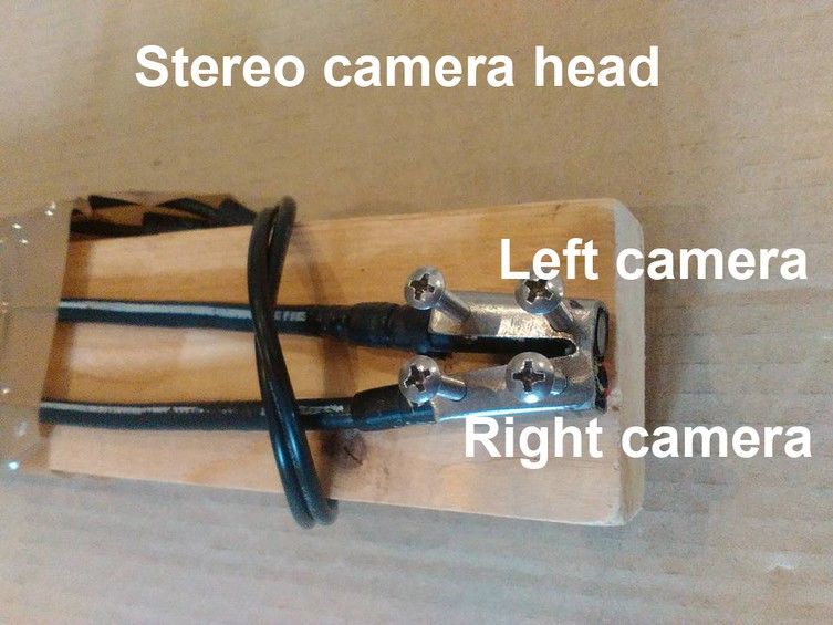
Copyright © 2016 ViewPoint 3D                                                                                         Viva3D Stereo Vision Processing - User Manual

Stereo vision and depth
Viva3D's stereo image processing module calculates depth from rectified left and right images in real-time. Images can be supplied from stored pictures, stereo camera
feed, or side-by-side video (standard 3D glasses-type videos produced by video cameras).

The stereo module stores depth data in a 16-bit signed array, supporting 32,768 depth levels.

Given stereo cameras parameters such as ocular distance, focal length, pixel size,
etc., distance to scene objects can be calculated.

To illustrate this in more detail, Fig 7 shows the diagram of a simplified stereo
vision system, where both cameras are mounted parallel to each other, and have
the exact same focal length.

The variables in Fig 7 are: b is the baseline, or interocular distance between the
two cameras.

f is the focal length of a camera.
XA is the X-axis of a camera.
ZA is the optical axis of a camera.
P is a real-world point defined by the coordinates X, Y, and Z.
uL is the projection of the real-world point P in an image acquired by the left
camera.
uR is the projection of the real-world point P in an image acquired by the right           Fig 7
camera.

Since the two cameras are separated by distance “b,” both cameras view the
same real-world point P in a different location on the two-dimensional images
acquired. The X-coordinates of points uL and uR are given by:

uL = f * X/Z
 and
uR = f * (X-b)/Z

Distance between those two projected points is known as “disparity” and we can use
the disparity value to calculate depth information, which is the distance between real-
world point “P” and the stereo vision system.

disparity = uL – uR = f * b/z
depth = f * b/disparity

A functional stereo vision system is more complex, as shown in Fig 8, but the same
fundamental principles apply.                                                                   Fig 8

Document: DM-06-120-021                                                                                                                                             6
Copyright © 2016 ViewPoint 3D                                                                                               Viva3D Stereo Vision Processing - User Manual

The assumptions made for a simplified stereo vision system cannot be made for real-world systems. Even professional-grade cameras and lenses will introduce
distortion, and in order to compensate a stereo vision system must be calibrated. This process involves using a calibration target, for example a grid of dots or a
checker-board, and capturing images at different angles and depths to calculate image distortion, as well as the exact spatial relationship between the two cameras.
In order to optimize the accuracy of a stereo vision system, and accurately relate calculated image disparity to true depth data, there are several important
considerations and parameters:

For a simple stereo system, the depth of a point (z) is given by:

Z = f * b/d

where f is the focal length, b is the baseline, or interocular distance between the cameras, and d the disparity between corresponding points.

Depth resolution refers to the accuracy with which a stereo vision system can estimate
changes in the depth of a surface. Depth resolution is proportional to the square of the
depth and the disparity resolution, and is inversely proportional to the focal length and
the baseline, or distance between the cameras. Good depth resolution requires a
sufficiently large baseline distance in relation to the depth range, a sufficiently large focal
length, and a small depth value for a given disparity resolution.

Example miniature stereo vision system
Measurable depth is limited by the resolution of the cameras, which relates directly to the
disparity value. At greater depth disparity tends to zero. With a greater field of view
disparity reduces to zero at a lower depth. Thus a greater field of view lowers the
maximum measurable depth, however, that can be compensated for by using higher
resolution camera sensors.

Disparity is firstly measured in pixels and then converted to meters or millimetres.
The full formula is then:                                                                            Fig 9 Disparity values as a function of depth, using a focal length of 8mm,
                                                                                                     baseline of 10cm, and pixel size of 7.5 microns.
        Baseline * Focal length
Depth = -----------------------------
        Pixel disparity * Pixel size

Using the following set-up:
Baseline (b) = 8.5 mm
Focal length (f) = 4.0 mm
Pixel size (p) = 4.4 um (0.0044 mm)

The smallest measurable disparity is 1 pixel.
Give these parameters:

Depth = (8.5*4.0)/(1*0.0044) = 7,727 mm = 7.7m

Document: DM-06-120-021                                                                                                                                                        7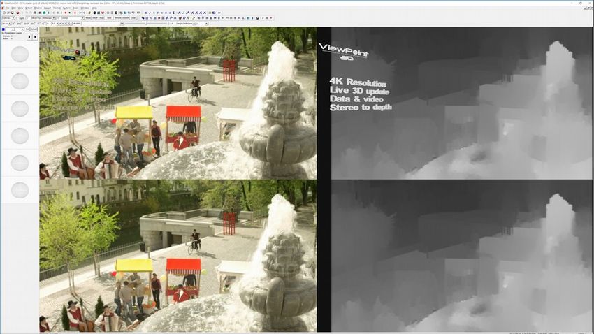
Copyright © 2016 ViewPoint 3D                                                                                            Viva3D Stereo Vision Processing - User Manual

Using miniature cameras with these specifications, the maximum depth range is 7.7m. Note: measurements at the far-end distance will be extremely inaccurate.

Given these parameters, the next possible disparity step (2 pixels) occurs at a depth of 3.85m, the following step (3 pixels) at 1.925m, jumping to 32 pixels, we reach
0.24m, or 24cm. Halving the baseline (interocular distance) to 4.25mm would halve the maximum range to 3.85m, and reducing the range at 32 pixels to 12cm,
increasing accuracy at the near-end. Halving the focal length would also halve the range, increasing near-end accuracy. Depth resolution can also be improved by
decreasing the pixel size, i.e. increasing camera sensor resolution.

Using a sensor with a pixel size of 0.0044 mm, with a horizontal resolution of 640 pixels, and sensor of 6.2 mm wide. If we double the number of pixels in the same
area this would double the maximum range without affecting the near-end resolution (because near-end limitations are determined by baseline and focal length, which
stay the same).

Pixel noise
Commercial grade sensors, such as those in boroscopes, have high-levels of noise which adversely affect disparity calculations due to increased block matching errors.
For accurate depth determination, we need to use sensors with low noise, featuring automatic exposure control, correlated double sampling and high dynamic range
across the required operational temperature range.

Conclusion
As we can see from these results, accurate close-up depth resolution using miniature cameras requires high-resolution miniature sensors, with fine tolerances in terms
of both electrical and mechanical specifications.

Stereo vision Applications using Viva3D
Stereo vision is well suited to applications that require object or obstacle location data, which can be used to guide the movement of a robot or robotic arm. For
navigating autonomous vehicles, depth information is used to measure the size and distance of obstacles for accurate path planning and obstacle avoidance.

Stereo vision systems produce a rich set of information for navigation applications, and can perform well even in changing light conditions given suitable image
sensors, and not solely limited to the visible light spectrum.

A stereo vision system is also useful in industrial automation tasks, such as bin-picking and assembly. A bin-picking application requires a robot arm to pick a specific
object from a container that holds several different kinds of parts. A stereo vision system can provide an inexpensive way to obtain 3D information and determine
which parts can be safely grasped. It can also provide precise locations for individual products in a crate, or during automated assembly tasks.

Document: DM-06-120-021                                                                                                                                                   8
Copyright © 2016 ViewPoint 3D                                                                                         Viva3D Stereo Vision Processing - User Manual

Chapter 2 - 3D Display of Stereo vision input
One use of the depth map is to display a 3D projection of the external scene within the Viva3D scene, or on an external 3D autostereoscopic monitor.

Viva3D employs two techniques to convert stereo input to 3D:-

    1.   Direct depth map display, in 2D+Depth formats; standard and quad
         mode for Dimenco and other 2D+Depth devices, see Fig 10.

    2.   Depth Modulated Convergent Radial projection (DM-CRP) of a high-
         resolution mesh within 3D space, see Fig 11 & 12.

1. 2D+Depth, Fig 10, the colour image is shown left-side, and depth right-side.
The external monitor recreates multiple views for projection of a 3D image.

2. Depth modulated projection, Figs 11 & 12, shows the external scene
recreated in real-time within the 3D CG space with excellent depth and colour
fidelity. The radial convergent method ensures that the viewer only sees a
portion of the side elevations at any given angle, allowing, in the case of multi-
view autostereoscopic projection, the views to be recreated accurately, and with              Fig 11 showing direct depth to frame-buffer in 2D quad mode
side pixels covering de-occlusion areas: see Fig 13 showing DM-CRP method.

 Fig 10 showing depth modulated mesh in 2D+Depth mode                                Fig 12 showing depth modulated mesh (test mode)

Document: DM-06-120-021                                                                                                                                         9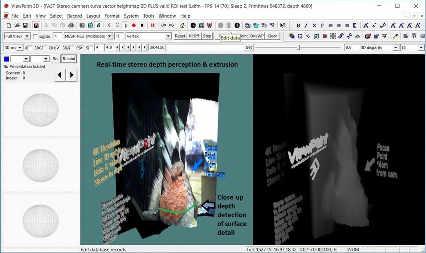
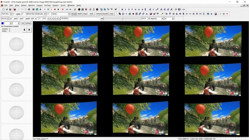
Copyright © 2016 ViewPoint 3D                                                                                       Viva3D Stereo Vision Processing - User Manual

Chapter 3 - Conversion to Multiview autostereoscopic interweave
Using a depth-modulated convergent radial projected mesh (DMCRP) allows us to render all the required views of the external 3D scene captured in real-time by the
stereo camera in order to interweave the views for multiview autostereoscopic
displays.

Fig 13 shows the left-camera image, and the calculated depth map.

Fig 14 shows the same scene rendered as 9 views from different camera angles.

Fig 15 finally shows the scene encoded in multiview interweave, ready for
display on a glasses-free 3D monitor.

The DMCRP technique was developed at ViewPoint 3D to enable real-time
viewing of stereo camera images on multi-view autostereoscopic monitors with
sufficient efficiency to operate on low-cost AMD APU and Intel Atom Gen 8
graphics processors.

In addition, the external 3D converted image can then be 3D subtitled within
Viva3D.                                                                         Fig 13 showing depth modulated mesh 2D+Depth mode

   Fig 14 showing same depth modulated mesh now in 9-views                      Fig 15 showing same mesh in multi-view autostereoscopic interweave

Document: DM-06-120-021                                                                                                                                             10
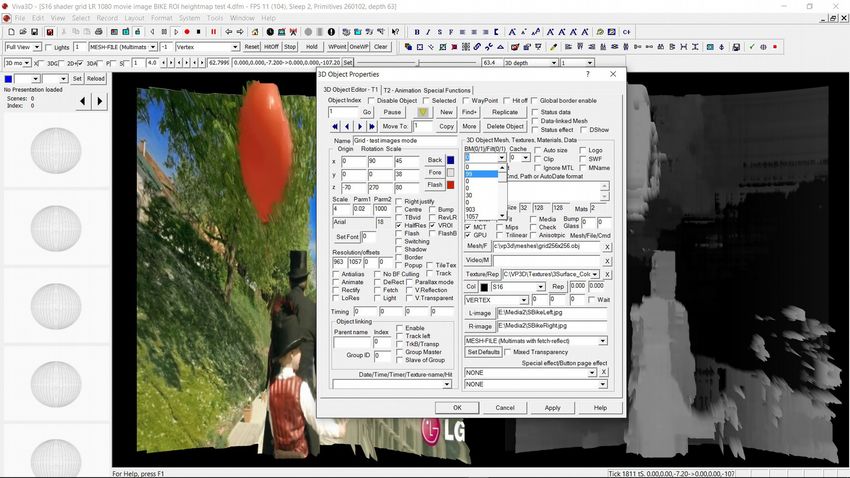
Copyright © 2016 ViewPoint 3D                                                                                          Viva3D Stereo Vision Processing - User Manual

Chapter 4 – Adjusting Stereo Marching parameters
Stereo matching in real-time on commercial computer systems requires a complete understanding of the stereo matching and filtering algorithms, and also parallel
processing on the CPU and GPU. The rendered image below has post-filtering disabled with the setting “99” shown below. Setting to 0 or 1 enables the filters.
A complete overview of all these processes is beyond the scope of this publication, which is limited to the adjustment of key parameters using the Viva3D object editor
shown below. Tab 1 of the editor shows the parameters selecting stereo matching and filtering algorithm, and the region of interest (ROI), plus filtering parameters.

In addition, depth map resolution can be reduced by a factor of 2 (LoRes), and/or height reduction only (HalfRes).

Document: DM-06-120-021                                                                                                                                             11
Copyright © 2016 ViewPoint 3D                                                                                           Viva3D Stereo Vision Processing - User Manual

Tab 2 of the editor allows adjustment of the key stereo matching parameters, maximum disparity (MDisp), minimum disparity (LR-Sht), Sum of absolute difference
window size (SADSze), and filter Lambda and sigma values.
In addition, the depth map may be clipped (Clip pixel coords 0.0-1.0), and range limited (TopH – 0.0 1.0), with a height multiplier (H-Mult), and base height for over-
range depth values (BaseH).

The above rendered image shows stereo matching using the fastest stereo matching mode without post filtering (see tab 1 setting of 99, which disables filtering).
As each application requires different settings, advice is available on settings per each system configuration.

Document: DM-06-120-021                                                                                                                                              12
Copyright © 2016 ViewPoint 3D                                                                                             Viva3D Stereo Vision Processing - User Manual

Adjusting settings using slider control

Viva3D has a multifunction slider control that can be used to adjust the stereo matching parameters while viewing the results in real-time.

How to use: With you stereo content display, left-click the stereo object, usually object 1. You can also double-click and navigate to the stereo object.

As can be seen in Fig 18, slider functions are selected with a drop-down control on the toolbar.
To the right of the function selection is a range control, often set when the function is chosen.

Once the function is selected, the available control modifiers are shown:

3D disparity is used for autostereoscopic display, but holding down the shift key accesses the stereo
displacement, value in steps of 16, and with the Ctrl key, lambda, and with the Alt key sigma.

Stereo displacement (16, 32... 128...): This value should match the maximum displacement between
your left and right images. Any objects in your images with greater displacement will yield invalid
disparity values, so its important to calculate this correctly.

Lambda: Typical value 8000. This parameters controls the post-filtering of the depth map, and
controls how strongly the depth map is forced to match the edges in the source image. Larger values
force the depth map to more closely adhere to the object outlines in the source.

Sigma: Typical value 0.8 – 2.0. This parameters controls post-filter pixel sensitivity.                   Fig 18 showing multifunction slider interface
If set too low, textures in the source images can cause false disparity results, if set too high, depth
details can be lost, resulting in a blurring of the depth map.

Some experimentation with these settings will usually be needed to achieve the best depth map results for any given camera set-up and scene type.

Left image shift control – minimum disparity:

This is a critical parameter to enable accurate depth calculation. Moving the slider to usually a negative value will yield instant changes in the display depth map: note
to display the depth-map ensure that the 2D+ checkbox is set on the toolbar.

Document: DM-06-120-021                                                                                                                                                 13
Copyright © 2016 ViewPoint 3D                                                                                           Viva3D Stereo Vision Processing - User Manual

Sum of Absolute Difference window size:

Disparity between left and right images is calculated based on pixel block matching. This parameter sets the size of the block to be matched.

Speckle filter (post-filter):

The speckle parameters can be used to remove noise from the images to reduce depth errors. At object boundaries speckles or spikes can occur in the disparity map
where background and foreground pixels between images get compared near to object boundaries. These values clamp the required number of pixels that can cause a
speckle to occur. This may not be available in all modes.

Texture threshold & Uniqueness (post-filter):

The texture threshold filters out areas with insufficient detail for accurate matching.
The uniqueness parameter sets the cap on pixels with insufficient differentiation compared to surrounding pixels. This is very useful for removing erroneous disparity
values in areas such as sky.

Image clip region:

Stereo matching can be reduced to a specific area of left and right images. This can increase speed considerably by eliminating borders of low interest.
Values are 0.0 – 1.0, 1.0 being equal to the maximum width or height.
These values are stored in tab 2 of the object editor, usually in object 1.

Document: DM-06-120-021                                                                                                                                              14
Copyright © 2016 ViewPoint 3D                                                                                           Viva3D Stereo Vision Processing - User Manual

3D depth:

In object 0, the main camera object, tab 2, there are two parameters for depth. The first is the default camera depth, also used for the depth display in 2D+Depth mode,
where the depth map is presented on the right side. This format generates a full 3D display on 2D+Depth monitors such as Dimenco and Philips WOWvx.

In scenes that require a shadow, the second depth parameter is used in the rendering of the shadow depth map.

Having two values, allows the setting of the optimal camera depth for the scene to be rendered, and correct depth for the shadow map.

Conclusion
Viva3D provides a unified 3D rendering environment in which stereo content, from cameras, side-by-side video or still LR images, can be displayed in real-time on 2D
and 3D monitors. In addition, the content can be 3D-subtitled with static and live data.

This makes Viva3D ideal for playing back stereo content in real-time, especially when data-driven subtitling is required.

Viva3D can be used to:-

    ●    Playback standard side-by-side glasses-3D movies on 2D and 3D glasses-free displays.

    ●    Real-time playback of remote stereo camera feed with 2D and 3D subtitling with live-data feed on 2D and 3D glasses-free displays.

    ●    Playback SBS movies with 2D and 3D subtitling on 2D and 3D glasses-free displays.

    ●    Real-time exterior environment depth calculation for motion detection or collision avoidance.

    ●    General purpose 3D content creation and presentation tool.

Please contact our computer science department for more information at info@viewpoint-3d.com

Document: DM-06-120-021                                                                                                                                              15
You can also read