Vortex states in an acoustic Weyl crystal with a topological lattice defect
←
→
Page content transcription
If your browser does not render page correctly, please read the page content below
ARTICLE
                   https://doi.org/10.1038/s41467-021-23963-7                OPEN

                  Vortex states in an acoustic Weyl crystal with a
                  topological lattice defect
                  Qiang Wang           1, Yong Ge2, Hong-xiang Sun                  2,   Haoran Xue          1,   Ding Jia2, Yi-jun Guan2, Shou-qi Yuan            2 ✉,

                  Baile Zhang         1,3 ✉ & Y. D. Chong 1,3 ✉
1234567890():,;

                  Crystalline materials can host topological lattice defects that are robust against local
                  deformations, and such defects can interact in interesting ways with the topological features
                  of the underlying band structure. We design and implement a three dimensional acoustic
                  Weyl metamaterial hosting robust modes bound to a one-dimensional topological lattice
                  defect. The modes are related to topological features of the bulk bands, and carry nonzero
                  orbital angular momentum locked to the direction of propagation. They span a range of axial
                  wavenumbers defined by the projections of two bulk Weyl points to a one-dimensional
                  subspace, in a manner analogous to the formation of Fermi arc surface states. We use
                  acoustic experiments to probe their dispersion relation, orbital angular momentum locked
                  waveguiding, and ability to emit acoustic vortices into free space. These results point to new
                  possibilities for creating and exploiting topological modes in three-dimensional structures
                  through the interplay between band topology in momentum space and topological lattice
                  defects in real space.

                  1 Divisionof Physics and Applied Physics, School of Physical and Mathematical Sciences, Nanyang Technological University, Singapore, Singapore.
                  2 Research  Center of Fluid Machinery Engineering and Technology, School of Physics and Electronic Engineering, Jiangsu University, Zhenjiang, China.
                  3 Centre for Disruptive Photonic Technologies, Nanyang Technological University, Singapore, Singapore. ✉email: shouqiy@ujs.edu.cn; blzhang@ntu.edu.sg;

                  yidong@ntu.edu.sg

                  NATURE COMMUNICATIONS | (2021)12:3654 | https://doi.org/10.1038/s41467-021-23963-7 | www.nature.com/naturecommunications                             1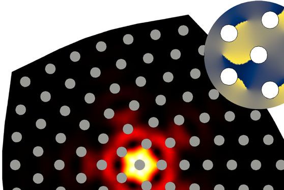
ARTICLE                                                                 NATURE COMMUNICATIONS | https://doi.org/10.1038/s41467-021-23963-7

T
        opological lattice defects (TLDs) are crystallinity-breaking         Results
        defects in lattices that cannot be eliminated by local               Design of the Weyl acoustic structure. The emergence of a TLD-
        changes to the lattice morphology, due to their nontrivial           bound topological mode is conceptually illustrated in Fig. 1a. In a
real-space topology1. Although they give rise to numerous                    Weyl semimetal, topologically-charged Weyl points in the 3D bulk
important physical effects in their own right2, TLDs can have                imply the existence of Fermi arc modes on 2D external surfaces of
especially interesting consequences in materials with topologically          the crystal. In the 2D surface momentum space, each Fermi arc
nontrivial bandstructures3–8. For instance, Ran et al. have shown            extends between the projections of two oppositely-charged Weyl
theoretically that introducing a screw dislocation into a three              points. The introduction of a TLD into the Weyl crystal breaks
dimensional (3D) topological band insulator induces the forma-               translational symmetry in the x–y plane while maintaining it along
tion of one-dimensional (1D) helical defect modes, which are                 z, and generates modes that are spatially localised to the 1D string
protected by the interplay between the Burgers vector of the                 formed by the TLD. Viewed from momentum space, the TLD-
defect and the topology of the bulk bandstructure5. Aside from               bound modes extend between the projections of the two Weyl
topological band insulators5,9–12, other topological phases are              points into the 1D momentum space kz.
predicted to have their own unique interactions with TLDs,                      Recently, the discovery of higher-order topological materials52
including Weyl semimetals, topological crystalline insulators, and           has led to the idea of higher-order Weyl and Weyl-like
higher-order topological insulators13–18. TLD-induced modes                  phases53–61, which can host “higher-order Fermi arcs”56–58,61.
provide a way to probe bandstructure topology independent of                 Like the TLD-bound modes discussed in this paper, higher-order
standard bulk-boundary correspondences6–8,11,15,17, and may                  Fermi arc modes are one-dimensional, but they arise from a
give rise to exotic material properties such as anomalous torsional          completely different mechanism involving higher-order topolo-
effects13. Experimental confirmations have, however, been ham-                gical indices56,57,61. Moreover, they lie along external hinges,
pered by the difficulty of accessing TLDs in real topological                 whereas the present TLD-bound modes are localised to the line of
materials19–21.                                                              the TLD, embedded inside a 3D bulk.
   Recently, various groups have turned to classical wave                       We designed and fabricated a 3D acoustic crystal formed by
metamaterials22–26 to perform the experimental studies of the                chirally structured layers stacked along z, as shown in Fig. 1b–e.
interplay between TLDs and topological bandstructures, includ-               Without any TLD, an x–y cross section of the structure would
ing the demonstration of topologically-aided trapping of light on            form a triangular lattice. The TLD is introduced by a “cut-and-
a dislocation23, robust valley Hall-like waveguiding along dis-              glue” procedure in which a π/3 wedge is deleted (Fig. 1c inset)
clination lines24, and defect-induced fractional modes25,26. The             and the edges are reattached by deforming the rest of the lattice
preceding studies have all been based on two dimensional (2D)                (see Methods). The experimental sample is formed by stacking
lattices; 3D lattices with TLD-induced topological modes have                3D-printed structures, with a total of 21 layers (see Methods); a
thus far only been investigated theoretically.                               photograph is shown in Fig. 1e.
   Here, we design and experimentally demonstrate a 3D acoustic                 The 3D Brillouin zone of the acoustic crystal, in the absence of
metamaterial that hosts topological modes induced by the pre-                the TLD, is depicted in the left panel of Fig. 2a. Weyl points exist
sence of a TLD. Without the TLD, the bulk metamaterial forms a               at K and K 0 (H and H 0 ), with topological charge +1 (−1)39,62,63;
Weyl crystal, whose 3D bandstructure contains topologically                  for details, refer to Supplementary Note 1. Consider the Weyl
nontrivial degeneracies called Weyl points27–41. Weyl crystals are           point at K or K 0 (the analysis for H and H 0 is similar). In its
known to exhibit, along their 2D external surfaces, Fermi arc                vicinity, the wavefunctions are governed by the effective
states that are protected by the topology of the Weyl points32,33.           Hamiltonian
The introduction of the defect generates a family of modes
localised to the line of the TLD (in real space). Moreover, in a                                H ¼ iðτ z σ x ∂x þ σ y ∂y Þ þ kz τ z σ z ;     ð1Þ
manner analogous to the formation of regular Fermi arcs, the                 where τi (σi) denotes valley (sublattice) Pauli matrices, we have
modes span the projections of two Weyl points of opposite                    rescaled each spatial coordinate so that the group velocity is unity,
topological charge in the axial momentum space kz. The TLD-                  and kz is the wavenumber in the z direction.
bound modes for each kz can be interpreted as a 2D bound state
generated by a strongly localised pseudo-magnetic flux associated
with the TLD, in accordance with earlier theoretical predictions             Pseudo-magnetic flux of the lattice defect. With the introduction
about disclinations in 2D topological materials8. Hence, these               of the TLD, kz remains a good quantum number; in the x–y plane,
modes arise from the interplay between the TLD and the 3D                    the distortion introduced by the TLD can be modelled as a matrix-
Weyl bandstructure. The TLD-bound modes carry nonzero                        valued gauge field8 that mixes the valleys (i.e., K with K 0 and H with
orbital angular momentum (OAM), locked to their propagation                  H 0 ). The effective Hamiltonian can be brought back into block-
direction. For each kz, the sign of the OAM depends on the Chern             diagonal form by a unitary transformation8, whereby the Hamil-
number of the 2D projected band structure, and matches the                   tonian for each block has the form of Eq. (1) but modified by
chirality of the robust localised state that appears in a Chern                          τ z ! τ 0 ; ∇ ! ∇ þ iτ 0 A; A ¼ ð4ΩrÞ1 eθ ;           ð2Þ
insulator on a 2D surface with singular curvature42–45—a pre-
diction that has never previously been verified in an                         where τ 0 ¼ ±1 is the block index, r is the radial coordinate and eθ is
experiment8,46,47. To our knowledge, this is also the first                   the azimuthal unit vector in the unfolded space, and the factor
demonstration of a 3D topology-induced mode carrying nonzero                 Ω = 5/6 is the number of undeleted wedges. Unlike previously stu-
OAM. Classical waves with nonzero OAM have a variety of                      died strain-induced pseudo-magnetic fluxes in Weyl semimetals63–65,
emerging applications including vortex traps and rotors48,49 and             the pseudo-magnetic flux here is strongly localised8,66. Moreover,
OAM-encoded communications50. Although chiral structures                     unlike previous studies of pseudo-magnetic fluxes generated by screw
have previously been studied for the purposes of OAM wave-                   dislocations, the pseudo-magnetic flux is kz-independent5,13.
guiding, those waveguides support multiple OAM modes with                       Viewed from 2D, the pseudo-magnetic flux induces topologi-
different propagation constants51; by contrast, the present topo-            cally protected chiral defect states. For each kz > 0, one can
logical waveguide supports, for each kz, a single robust bound               show5,8 that there is a single bound solution (among the two
mode with nonzero OAM.                                                       Weyl Hamiltonians) localised at r = 0. This remains true even

2                NATURE COMMUNICATIONS | (2021)12:3654 | https://doi.org/10.1038/s41467-021-23963-7 | www.nature.com/naturecommunications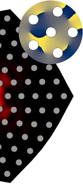
NATURE COMMUNICATIONS | https://doi.org/10.1038/s41467-021-23963-7                                                                        ARTICLE

     a                                                                             b                                       c
              Bulk
                                          Weyl Points

                                                                    ky
                                                                         kx

         Cutting Surface                                                      kz

                                                                                                                                                Lattice
                                                                                                      OAM-carrying                              defect
                                     Conventional 2D Fermi Arc           kx                           defect mode
                                                                                   d                                       e
                                                                              kz                  d
                                                                                                  Δ
      Toplogical Lattice
          Defect                                                                                                     L
                                                                                   h1

                                                                                        a

                                                                              kz    z
                                   TLD-induced bound modes                              y         D0                                           10 cm
                                                                                            x

Fig. 1 Weyl acoustic structure with a topological lattice defect (TLD). a Conceptual illustration of the formation of a mode bound to the TLD. Top row: a
bulk crystal (left) hosts two Weyl points with opposite topological charges in 3D momentum space (right). Middle row: truncating the crystal (left) creates
a Fermi arc extending between the projections of the Weyl points in the 2D surface momentum space (right). Bottom row: adding a TLD (left) results in
bound modes that extend between the projections of the Weyl points into the 1D momentum space (right). b Schematic of an acoustic lattice made of
chiral layers with a central TLD, stacked along z. A section is omitted to show the internal structure. TLD-bound mode carrying nonzero orbital angular
momentum (OAM) propagates along the TLD (pink region). c Top-down schematic of one layer. The TLD is generated by deleting a π/3 wedge from a
triangular lattice (inset). d Close-up view of one unit cell. The periodicity in z is L = 1.8 cm. Each unit cell consists of an air-filled sheet of thickness
h1 = 0.8 cm, with a central solid rod of diameter D0 = 1.6 cm ringed by six skewed air-filled tubes of diameter d = 0.9 cm in a hexagonal arrangement. The
tubes advance by π/6 aroundpffiffiffi the hexagon between layers. The spacing between the central rod and the tubes is Δ = 0.1 cm, and the side length of the
hexagonal cell is a ¼ 4= 3 cm. All other regions are solid resin. e Photograph of the experimental sample with 21 layers. Blue dashes indicate one of
the layers, and the arrow indicates one of the gaps for inserting acoustic probes.

when kz is non-perturbative. For fixed kz, the lattice in the                       locked to the propagation direction, distinguishes them from
absence of the TLD maps to a 2D Chern insulator whose Chern                        previously studied topological defect modes67–70 and hinge
numbers switch sign with kz (the gap closes at 0 and ±π/L); upon                   modes56,57,61 that have zero OAM. Moreover, we have verified
introducing the TLD via the cut-and-glue construction, one of the                  numerically that the TLD-bound modes’ localisation and OAM
two sub-blocks in the effective Hamiltonian (τ 0 ¼ 1 for 0 < kz <                  are robust to in-plane disorder, consistent with their topological
π/L, and τ 0 ¼ 1 for −π/L < kz < 0) exhibits a solution that is                   origin (see Supplementary Note 3).
localised to the TLD8. As we vary kz, this family of solutions spans
the projections of the Weyl points at K(K 0 ) and H(H 0 ). Note that               Spectrum and field distribution measurements. We performed
the overall acoustic structure preserves time-reversal symmetry                    a variety of experiments to characterise the TLD-bound modes in
(T), but the individual Hamiltonian sub-blocks effectively break                   the fabricated structure. First, we investigated their dispersion
T; the defect mode at − kz thus serves as the time-reversed                        curve by threading an acoustic source into the bottom layer of the
counterpart of the defect mode at kz, with opposite chirality. For                 sample, near the center of the TLD. A probe is inserted into the
further details, refer to Supplementary Note 2.                                    other 20 layers in turn, via the central air sheet in each layer, as
   The upper panel of Fig. 2b shows the numerically computed                       indicated by the blue arrow in Fig. 1d. The acoustic pressure,
acoustic band diagram for the TLD-free bulk structure, projected                   measured close to the center of the TLD, is Fourier transformed
onto kz. The relevant bands along K-H (M-L) are plotted in green                   to obtain the spectral plot shown in Fig. 3a. The overlaid red
(orange), and the gap region is shown in white. The lower panel                    dashes are the numerically obtained TLD-bound mode dispersion
of Fig. 2b shows the corresponding band diagram for a structure                    curve (Fig. 2b), which closely matches the intensity peaks in the
with a TLD, which is periodic along z and has the same x–y                         experimental results. We then repositioned the source and probe
profile as the experimental sample (Fig. 1b–e). These numerical                     away from the TLD, obtaining in the spectrum shown in Fig. 3b;
results reveal the existence of TLD-bound modes, plotted in red,                   this matches the bulk spectrum obtained numerically, with the
which occupy the gap and span almost the entire kz range. (Near                    spectral intensities peaking in the bulk bands. For details about
kz = 0 and kz = π/L, they are difficult to distinguish from bulk                    the source and probe positions, see Supplementary Note 4.
modes due to finite-size effects.)                                                     The acoustic pressure intensity at kz = π/2L is plotted versus
   In Fig. 2c,d, we show the mode distributions for the TLD-                       frequency in Fig. 3c. A narrow peak corresponding to the TLD-
bound modes at kz = ±0.5π/L. The modes are strongly localised to                   bound modes is clearly observable within the bulk gap, with only
the center of the TLD; their intensity profiles are identical since                 a small frequency shift of 80 Hz relative to the numerically
the two modes map to each other under time reversal. The phase                     predicted eigenfrequency. For excitation near the TLD, the
distributions (inset) reveal that the kz > 0 (kz < 0) TLD-bound                    measured intensity distribution at frequency f = 4.924 kHz is
mode has winding number +1 (−1). This winding number is tied                       plotted in Fig. 3d, showing strong localisation around the TLD.
to the Chern number of the 2D projected band structure for fixed                    The radial dependence of the intensity distribution is plotted in
kz. The fact that the TLD-bound modes carry nonzero OAM,                           Fig. 3e (note that the apparent irregularity arises from the fact

NATURE COMMUNICATIONS | (2021)12:3654 | https://doi.org/10.1038/s41467-021-23963-7 | www.nature.com/naturecommunications                                  3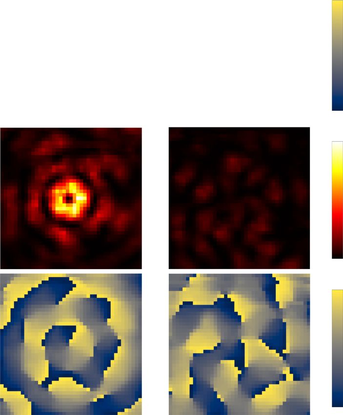
ARTICLE NATURE COMMUNICATIONS | https://doi.org/10.1038/s41467-021-23963-7
a b 6.0 Periodic bulk
5.5
A H' K-H
L 5.0
Frequency (kHz)
M-L
H K' 4.5
Γ
M 6.0 Finite structure
K
5.5
with defect
kz 5.0
ky H/H' K /K' H/ H'
Defect
4.5 modes
kx 0 kz
0 0.5π/L π/L
Axial wavenumber k z
c k z = 0.5π/L d k z = -0.5π/L
Max
Intensity π
Phase
0 -π
Fig. 2 Numerical characterisation of the TLD-bound modes. a Left panel: 3D Brillouin zone of the acoustic crystal without a TLD. Weyl points occur at K
and K 0 with topological charge +1 (cyan dots), and at H and H0 with charge −1 (magenta dots). Right panel: projection of the Weyl points onto kz, with red
dashes indicating the TLD-bound modes. b Numerical bandstructures. Upper plot: bands along K-H and M-L for the periodic bulk. Lower plot: bands for
a structure with a TLD (with the same cross sectional profile as in Fig. 1b–e) and periodicity L along z; band edge (in-gap) modes are plotted in blue (red).
In-gap regions are shown in white. All bands, including the TLD-bound modes, are symmetric around kz = 0; only the kz > 0 range is plotted here.
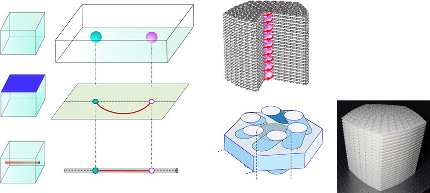
c, d Calculated acoustic pressure intensity distributions in the x–y plane, with z at the midpoint of the structure’s central air sheet, for the TLD-bound modes
at kz = π/2L (c) and kz = − π/2L (d). Both modes have frequency 4.844 kHz. The grey circles are the solid rods passing through the air sheet. Insets: phase
distribution of acoustic pressure near the TLD, showing that the two modes have opposite OAM.
that the measurement points lie at different azimuthal angles). dividing by the averaged intensity in the bottom layer to nor-
The measurement data is in good agreement with the numerically malise away the frequency dependence of the source. For a CCW
obtained TLD-bound mode profiles. From a linear least squares vortex source, a strong peak is observed within the range of
fit of the semi-logarithmic plot, using measurement data up to a frequencies where TLD-bound modes are predicted to exist. For a
radial distance of 12 cm, we find a localisation length of 2.38 cm, clockwise (CW) vortex source, the intensity is low (the non-
which is on the order of the mean distance between unit cells (i.e., vanishing intensity is likely due to finite-size effects).
the approximate lattice constant). Figure 4c–d shows the intensity and phase distributions
Figure 3f plots the phase of the measured acoustic pressure measured in the top layer at 5.6 kHz, confirming that the TLD-
signal versus azimuthal angle for kz = π/2L and f = 4.924 kHz. The bound modes are preferentially excited by the CCW vortex.
different data series in this plot correspond to measurement points After the TLD-bound modes have passed through the
at different radial distances. The phase is observed to wind by +2π structure, they emit an acoustic vortex into free space at the far
during a counterclockwise (CCW) loop encircling the TLD, surface. In Fig. 4e–h, we show the intensity and phase
consistent with the numerically obtained eigenmode (Fig. 2c), distributions measured by an external acoustic probe positioned
which implies that the TLD-bound mode has OAM of +1. 2 mm above the top surface of the sample. For a CCW vortex
source in the bottom layer, a CCW vortex is emitted from the top
layer, at the position of the TLD; for a CW vortex source, the
Excitation by vortex sources. To demonstrate the physical sig- emission is negligible due to the TLD-bound modes not being
nificance of the OAM carried by the TLD-bound modes, we excited. For frequencies outside the range of the TLD-bound
studied their coupling to external acoustic vortices. The experi- modes, the CW and CCW vortices both produce negligible
mental setup is shown in Fig. 4a. The vortex wave is generated in emission from the top layer (see Supplementary Note 4).
a cylindrical waveguide of radius 1.7 cm, attached to the bottom
layer of the sample at the center of the TLD. Figure 4b shows the
acoustic pressure intensity measured in the top layer, on the Discussion
opposite side of the sample from the source. This intensity is We have experimentally realised a 3D acoustic structure hosting
obtained by averaging over points closest to the TLD, and localised topological modes induced by a topological lattice
4 NATURE COMMUNICATIONS | (2021)12:3654 | https://doi.org/10.1038/s41467-021-23963-7 | www.nature.com/naturecommunications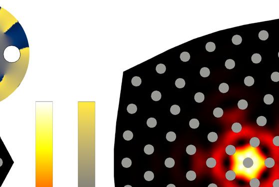
NATURE COMMUNICATIONS | https://doi.org/10.1038/s41467-021-23963-7 ARTICLE
a b c 1.0
6.0 6.0
Defect
Bulk
Frequency (kHz)
Frequency (kHz)
Relative Intensity
5.5 5.5
0.5
5.0 5.0
4.5 4.5
0.0
0 0.5π/L π/L 0 0.5π/L π/L 4.5 5.0 5.5 6.0
kz 0 Max kz Frequency (kHz)
Intensity
d f = 4.924kHz e f
0 2π
Relative Intensity (dB)
Measured
Measured Phase
φ
-20
π
-40
Simulated
0
0 5 10 15 20 0 π 2π
Radial Distance (cm) Azimuthal angle φ
Fig. 3 Experimental observation of TLD-bound modes. a Measured spectral intensity of the TLD-bound modes. With an acoustic source in the bottom
layer near the TLD, the acoustic pressure readings are Fourier transformed in z, and the mean in-plane intensity within 5 cm of the TLD is plotted. Red-and-
white dashes show the numerically obtained TLD-bound mode dispersion curve, and blue dashes show the numerically obtained band edges. b Spectral
intensity of bulk modes, obtained by placing the source and probe 14 cm and 10 cm away from the TLD, respectively. c Defect (red) and bulk (blue) spectral
intensities at kz = π/2L, with each curve normalised to its maximum value. d Measured in-plane intensity distribution at kz = π/2L and frequency
4.924 kHz. Each red circle is centered at a measurement point, and its area is proportional to the squared magnitude of the acoustic pressure. e Semi-
logarithmic plot of intensity versus radial distance from the TLD for the mode in (d). Red dots show the experimental results, taken at different azimuthal
angles, and orange dots show the profile of the numerically obtained TLD-bound eigenmode. f Left panel: measured phase signal versus azimuthal angle φ
at different radial distances near the TLD. Right panel: schematic of the measurement positions. In d and f, the grey circles indicate the solid rods.
defect. In real space, the modes lie along a 1D line formed by the Methods
defect, embedded within the bulk; in momentum space, they Lattice generation. The lattice was optimised by the the molecular dynamics
connect the projections of the Weyl points in the defect-free simulator LAMMPS75, using two types of particle interactions: (i) a three-body
Tersoff potential (SiC.tersoff), and (ii) a pairwise nearest-neighbour har-
crystal, and hence span the 1D Brillouin zone. This is, to our monic potential UðrÞ ¼ Kðr r 0 Þ2 (bond_style harmonic) with K = 20 and
knowledge, the first experimental demonstration of a defect- r0 = 0. Note that these particle interactions have no physical significance; they are
induced topological mode in any 3D system. For each momen- simply a convenient way to generate a lattice with minimal variation in inter-site
tum space slice (kz), the system maps onto a 2D Chern insulator distances24.
trapped on a surface with singular curvature. Theoretical studies
have previously shown that such a system hosts a robust localised Numerical simulation. All bandstructure calculations were performed using
defect mode tied to the Chern number of the 2D bulk COMSOL Multiphysics, with air density 1.18 kg m−3 and sound speed 343 ms−1.
bandstructure8,46,47. All air-solid interfaces are modeled as hard acoustic boundaries. For the
dispersion plot in the lower panel of Fig. 2b, we used periodic boundary
The TLD-bound modes carry nonzero OAM, locked to their conditions in the z direction, and plane wave radiation boundary conditions
propagation direction. This is a striking feature not possessed by in x and y.
topological defect modes based on other similar schemes; for
example, the localised topological modes of 2D Kekulé lattices
Experiments. The experimental samples were fabricated from photosensitive
carry zero winding number67–70. Our sample therefore serves as resin via stereolithographic 3D printing. For the dispersion measurements in
an OAM-locked acoustic waveguide, one whose operating prin- Fig. 3, the bottom surface of the sample is covered by a square plexiglass plate
ciples are very different from the chiral acoustic emitters71,72 and (length 500 mm), which acts as a hard acoustic boundary. A broadband
metasurfaces73,74 studied in previous works. This design may be acoustic signal is launched from a balanced armature speaker of around 1 mm
radius, driven by a power amplifier, and located at the center of the TLD at the
useful for applications of acoustic vortices, such as acoustic traps interface between the plate and the sample. Each acoustic probe is a micro-
and rotors48,49 and OAM-encoded communications50. Similar phone (Brüel & Kjær Type 4961, of about 3.2 mm radius) in a sealed sleeve
designs could be used to realise TLD-bound modes in photonics, with a tube of 1 mm radius and 250 mm length. The probes can be threaded
based on 3D photonic crystals30 or laser-written waveguide into the sample along the horizontal air regions to scan different positions
within each layer of the sample (see Supplementary Note 4). The measured
arrays35. data was processed by a Brüel & Kjær 3160-A-022 module to extract the
Finally, our work opens the door for further investigations frequency spectrum, with 2 Hz resolution. Spatial Fourier transforms are
into the numerous other effects of lattice defects in topological applied to the complex acoustic pressure signals to obtain the dispersion
materials. Many interesting phenomena in this area have been relation and field distributions.
For the experiment shown in Fig. 4, the CW and CCW waves are generated in a
proposed theoretically but have not thus far been observed, circular waveguide of radius 1.7 cm, into which three balanced armature speakers
including torsional chiral magnetic effects in Weyl semimetals are inserted. The signal amplitudes in the three speakers are kept the same, and the
and 1D helical defect modes in 3D weak topological phases are controlled by two waveform generators (Agilent type 33500B). The CW
insulators5,13,15. and CCW waves were generated by setting the relative phases to (0∘, ±120∘, ±240∘).
NATURE COMMUNICATIONS | (2021)12:3654 | https://doi.org/10.1038/s41467-021-23963-7 | www.nature.com/naturecommunications 5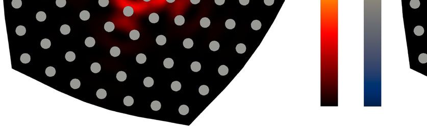
ARTICLE                                                                   NATURE COMMUNICATIONS | https://doi.org/10.1038/s41467-021-23963-7

                           a                         Ext. Probe               b                        1.0
                                                                                                                    CCW

                                                                                  Relative Intensity
                                                                 Int.                                  0.5
                                                                 Probe

                                                                                                                     CW
                                                   Vortex
                                                                                                         0
                                                   Excitation                                            4.0         5.0     6.0
                                                                                                               Frequency (kHz)
                                              CCW                                                              CW
                                                                                                                                         π
                             c                                              d

                                                                                                                              Phase
                                                                                                                                     -π
                               e                                              f                                                      Max

                                                                                                                             Intensity

                                                                                                                                         0
                               g                                                h                                                        π
                                                                                                                              Phase

                                                                                                                                         -π
Fig. 4 Selective excitation by a vortex source. a Schematic of the experiment. A counterclockwise (CCW) or clockwise (CW) acoustic vortex is
incident on the bottom of the sample, centered on the TLD. An external probe, 2 mm above the top surface, sweeps over a 20 cm × 20 cm area
(0.5 cm step size). An internal probe is inserted into the top layer. b Normalised acoustic pressure intensity versus frequency measured in the top
layer by the internal probe for a CCW (purple dots) and CW (orange dots) vortex source. The green region indicates the frequency range hosting
TLD-bound modes. c, d Acoustic pressure distribution in the top layer for a CCW (g) and CW (h) vortex source at 5.6 kHz (vertical dotted line in
b). The area and colour of each circle correspond to intensity and phase respectively. e, h Intensity distributions (e, f) and phase distributions (g, h)
measured by the external probe for a CCW (c) and CW (d) vortex source. The grey circles in (c–d) and white circles in (e–h) indicate the
structural rods.

6                  NATURE COMMUNICATIONS | (2021)12:3654 | https://doi.org/10.1038/s41467-021-23963-7 | www.nature.com/naturecommunications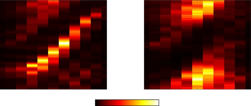
NATURE COMMUNICATIONS | https://doi.org/10.1038/s41467-021-23963-7                                                                                             ARTICLE

Data availability                                                                            28. Yang, B.-J. & Nagaosa, N. Classification of stable three-dimensional dirac
The data supporting the findings of this study are available from the Digital Repository of       semimetals with nontrivial topology. Nat. Comm. 5, 1–10 (2014).
Nanyang Technological University (DR-NTU) at https://doi.org/10.21979/N9/THY532.             29. Liu, Z. K. et al. Discovery of a three-dimensional topological dirac semimetal,
                                                                                                 na3bi. Science 343, 864–867 (2014).
                                                                                             30. Lu, L. et al. Experimental observation of weyl points. Science 349, 622–624
Code availability                                                                                (2015).
All numerical codes are available from the corresponding authors on reasonable request.
                                                                                             31. Fang, C., Chen, Y., Kee, H.-Y. & Fu, L. Topological nodal line semimetals with
                                                                                                 and without spin-orbital coupling. Phys. Rev. B 92, 081201 (2015).
Received: 11 December 2020; Accepted: 19 May 2021;                                           32. Xu, S.-Y. et al. Discovery of a weyl fermion semimetal and topological fermi
                                                                                                 arcs. Science 349, 613–617 (2015).
                                                                                             33. Lv, B. Q. et al. Experimental discovery of weyl semimetal taas. Phys. Rev. X 5,
                                                                                                 031013 (2015).
                                                                                             34. Bian, G. et al. Topological nodal-line fermions in spin-orbit metal pbtase 2.
References                                                                                       Nat. Comm. 7, 1–8 (2016).
1.    Mermin, N. D. The topological theory of defects in ordered media. Rev. Mod.            35. Noh, J. et al. Experimental observation of optical weyl points and fermi arc-
      Phys. 51, 591–648 (1979).                                                                  like surface states. Nat. Phys. 13, 611–617 (2017).
2.    Kosterlitz, J. M. Nobel lecture: topological defects and phase transitions. Rev.       36. Wang, Q., Xiao, M., Liu, H., Zhu, S. & Chan, C. T. Optical interface states
      Mod. Phys. 89, 040501 (2017).                                                              protected by synthetic weyl points. Phys. Rev. X 7, 031032 (2017).
3.    Jackiw, R. & Rossi, P. Zero modes of the vortex-fermion system. Nucl. Phys. B          37. Wu, W. et al. Nodal surface semimetals: theory and material realization. Phys.
      190, 681–691 (1981).                                                                       Rev. B 97, 115125 (2018).
4.    Lammert, P. E. & Crespi, V. H. Topological phases in graphitic cones. Phys.            38. Armitage, N. P., Mele, E. J. & Vishwanath, A. Weyl and dirac semimetals in
      Rev. Lett. 85, 5190–5193 (2000).                                                           three-dimensional solids. Rev. Mod. Phys. 90, 015001 (2018).
5.    Ran, Y., Zhang, Y. & Vishwanath, A. One-dimensional topologically protected            39. Li, F., Huang, X., Lu, J., Ma, J. & Liu, Z. Weyl points and fermi arcs in a chiral
      modes in topological insulators with lattice dislocations. Nat. Phys. 5, 298–303           phononic crystal. Nat. Phys. 14, 30–34 (2018b).
      (2009).                                                                                40. Yan, Q. et al. Experimental discovery of nodal chains. Nat. Phys. 14, 461–464
6.    Teo, J. C. Y. & Kane, C. L. Topological defects and gapless modes in insulators            (2018).
      and superconductors. Phys. Rev. B 82, 115120 (2010).                                   41. Xiao, M. et al. Experimental demonstration of acoustic semimetal with
7.    Juričić, V., Mesaros, A., Slager, R.-J. & Zaanen, J. Universal probes of two-              topologically charged nodal surface. Sci. Adv. 6, eaav2360 (2020).
      dimensional topological insulators: dislocation and π flux. Phys. Rev. Lett. 108,       42. Wen, X. G. & Zee, A. Shift and spin vector: new topological quantum numbers
      106403 (2012).                                                                             for the hall fluids. Phys. Rev. Lett. 69, 953–956 (1992).
8.    Rüegg, A. & Lin, C. Bound states of conical singularities in graphene-based            43. Parrikar, O., Hughes, T. L. & Leigh, R. G. Torsion, parity-odd response, and
      topological insulators. Phys. Rev. Lett. 110, 046401 (2013).                               anomalies in topological states. Phys. Rev. D 90, 105004 (2014).
9.    Slager, R.-J., Mesaros, A., Juričić, V. & Zaanen, J. The space group                   44. Rüegg, A., Coh, S. & Moore, J. E. Corner states of topological fullerenes. Phys.
      classification of topological band-insulators. Nat. Phys. 9, 98–102 (2013).                 Rev. B 88, 155127 (2013).
10.   Slager, R.-J., Mesaros, A., Juričić, V. & Zaanen, J. Interplay between electronic      45. Schine, N., Ryou, A., Gromov, A., Sommer, A. & Simon, J. Synthetic landau
      topology and crystal symmetry: dislocation-line modes in topological band                  levels for photons. Nature 534, 671–675 (2016).
      insulators. Phys. Rev. B 90, 241403 (2014).                                            46. Can, T., Chiu, Y. H., Laskin, M. & Wiegmann, P. Emergent conformal
11.   Slager, R.-J., Rademaker, L., Zaanen, J. & Balents, L. Impurity-bound states               symmetry and geometric transport properties of quantum hall states on
      and green’s function zeros as local signatures of topology. Phys. Rev. B 92,               singular surfaces. Phys. Rev. Lett. 117, 266803 (2016).
      085126 (2015).                                                                         47. Biswas, R. R. & Son, D. T. Fractional charge and inter-landau–level states at
12.   Slager, R.-J. The translational side of topological band insulators. J. Phys.              points of singular curvature. Proc. Nat. Acad. Sci. (USA) 113, 8636–8641
      Chem. Solids 128, 24–38 (2019).                                                            (2016).
13.   Sumiyoshi, H. & Fujimoto, S. Torsional chiral magnetic effect in a weyl                48. Skeldon, K. D., Wilson, C., Edgar, M. & Padgett, M. J. An acoustic spanner
      semimetal with a topological defect. Phys. Rev. Lett. 116, 166601 (2016).                  and its associated rotational doppler shift. New J. Phys. 10, 013018 (2008).
14.   Liu, J. & Balents, L. Anomalous hall effect and topological defects in                 49. Baresch, D., Thomas, J.-L. & Marchiano, R. Observation of a single-beam
      antiferromagnetic weyl semimetals: Mn 3 sn/ge. Phys. Rev. Lett. 119, 087202                gradient force acoustical trap for elastic particles: acoustical tweezers. Phys.
      (2017).                                                                                    Rev. Lett. 116, 024301 (2016).
15.   Soto-Garrido, R., Muñoz, E. & Juričić, V. Dislocation defect as a bulk probe of        50. Shi, C., Dubois, M., Wang, Y. & Zhang, X. High-speed acoustic
      monopole charge of multi-weyl semimetals. Phys. Rev. Res. 2, 012043 (2020).                communication by multiplexing orbital angular momentum. Proc. Natl Acad.
16.   van Miert, G. & Ortix, C. Dislocation charges reveal two-dimensional                       Sci. 114, 7250–7253 (2017).
      topological crystalline invariants. Phys. Rev. B 97, 201111 (2018).                    51. Wong, G. et al. Excitation of orbital angular momentum resonances in
17.   Li, T., Zhu, P., Benalcazar, W. A. & Hughes, T. L. Fractional disclination                 helically twisted photonic crystal fiber. Science 337, 446–449 (2012).
      charge in two-dimensional Cn-symmetric topological crystalline insulators.             52. Benalcazar, W. A., Bernevig, B. A. & Hughes, T. L. Quantized electric
      Phys. Rev. B 101, 115115 (2020).                                                           multipole insulators. Science 357, 61–66 (2017).
18.   Queiroz, R., Fulga, I. C., Avraham, N., Beidenkopf, H. & Cano, J. Partial lattice      53. Lin, M. & Hughes, T. L. Topological quadrupolar semimetals. Phys. Rev. B 98,
      defects in higher-order topological insulators. Phys. Rev. Lett. 123, 266802 (2019).       241103 (2018).
19.   Yazyev, O. V. & Louie, S. G. Electronic transport in polycrystalline graphene.         54. Roy, B. Antiunitary symmetry protected higher-order topological phases.
      Nat. Mater. 9, 806–809 (2010).                                                             Phys. Rev. Res. 1, 032048 (2019).
20.   Huang, P. Y. et al. Grains and grain boundaries in single-layer graphene               55. Călugăru, D., Juričić, V. & Roy, B. Higher-order topological phases: a general
      atomic patchwork quilts. Nature 469, 389–392 (2011).                                       principle of construction. Phys. Rev. B 99, 041301 (2019).
21.   Hamasaki, H., Tokumoto, Y. & Edagawa, K. Conductive and non-conductive                 56. Wang, H.-X., Lin, Z.-K., Jiang, B., Guo, G.-Y. & Jiang, J.-H. Higher-order weyl
      dislocations in bi-sb topological insulators. J. Phys. Soc. Japan 89, 023703               semimetals. Phys. Rev. Lett. 125, 146401 (2020b).
      (2020).                                                                                57. Ghorashi, S. A. A., Li, T. & Hughes, T. L. Higher-order weyl semimetals. Phys.
22.   Lin, Q., Sun, X.-Q., Xiao, M., Zhang, S.-C. & Fan, S. A three-dimensional                  Rev. Lett. 125, 266804 (2020).
      photonic topological insulator using a two-dimensional ring resonator lattice          58. Luo, L. et al. “Observation of a phononic higher-order weyl semimetal,” arXiv
      with a synthetic frequency dimension. Sci. Adv. 4, eaat2774 (2018).                        preprint arXiv:2011.01351 (2020).
23.   Li, F.-F. et al. Topological light-trapping on a dislocation. Nat. Commun. 9,          59. Wieder, B. J. et al. Strong and fragile topological dirac semimetals with higher-
      2462 (2018a).                                                                              order fermi arcs. Nat. Comm. 11, 1–13 (2020).
24.   Wang, Q., Xue, H., Zhang, B. & Chong, Y. D. Observation of protected                   60. Wu, W., Yu, Z.-M., Zhou, X., Zhao, Y. X. & Yang, S. A. Higher-order dirac
      photonic edge states induced by real-space topological lattice defects. Phys.              fermions in three dimensions. Phys. Rev. B 101, 205134 (2020).
      Rev. Lett. 124, 243602 (2020a).                                                        61. Wei, Q. et al. Higher-order topological semimetal in acoustic crystals. Nat.
25.   Liu, Y. et al. Bulk–disclination correspondence in topological crystalline                 Mater. https://doi.org/10.1038/s41563-021-00933-4 (2021).
      insulators. Nature 589, 381–385 (2021).                                                62. Xiao, M., Chen, W.-J., He, W.-Y. & Chan, C. T. Synthetic gauge flux and weyl
26.   Peterson, C. W., Li, T., Jiang, W., Hughes, T. L. & Bahl, G. Trapped fractional            points in acoustic systems. Nat. Phys. 11, 920–924 (2015).
      charges at bulk defects in topological insulators. Nature 589, 376–380 (2021).         63. Peri, V., Serra-Garcia, M., Ilan, R. & Huber, S. D. Axial-field-induced chiral
27.   Wan, X., Turner, A. M., Vishwanath, A. & Savrasov, S. Y. Topological                       channels in an acoustic weyl system. Nat. Phys. 15, 357–361 (2019).
      semimetal and fermi-arc surface states in the electronic structure of                  64. Jia, H. et al. Observation of chiral zero mode in inhomogeneous three-
      pyrochlore iridates. Phys. Rev. B 83, 205101 (2011).                                       dimensional weyl metamaterials. Science 363, 148–151 (2019).

NATURE COMMUNICATIONS | (2021)12:3654 | https://doi.org/10.1038/s41467-021-23963-7 | www.nature.com/naturecommunications                                                         7
ARTICLE                                                                              NATURE COMMUNICATIONS | https://doi.org/10.1038/s41467-021-23963-7

65. Ilan, R., Grushin, A. G. & Pikulin, D. I. Pseudo-electromagnetic fields in 3d          H.X., and H.-X.S. designed the experiments and fabricated the sample. Y.G., H.-X.S., D.J.
    topological semimetals. Nat. Rev. Phys. 2, 29 (2019).                                 and Y.-J.G. conducted the measurements. S.-Q.Y., B.Z. and Y.C. supervised the project.
66. González, J., Guinea, F. & Vozmediano, M. A. H. The electronic spectrum of            All authors contributed extensively to the interpretation of the results and the writing of
    fullerenes from the dirac equation. Nucl. Phys. B 406, 771–794 (1993).                the paper.
67. Gao, P. et al. Majorana-like zero modes in kekulé distorted sonic lattices. Phys.
    Rev. Lett. 123, 196601 (2019).
68. Menssen, A. J., Guan, J., Felce, D., Booth, M. J. & Walmsley, I. A. Photonic
                                                                                          Competing interests
                                                                                          The authors declare no competing interests.
    topological mode bound to a vortex. Phys. Rev. Lett. 125, 117401 (2020).
69. Gao, X. et al. Dirac-vortex topological cavities. Nat. Nanotech. 15, 1012–1018
    (2020).                                                                               Additional information
70. Noh, J. et al. Braiding photonic topological zero modes. Nat. Phys. 16, 989–          Supplementary information The online version contains supplementary material
    993 (2020).                                                                           available at https://doi.org/10.1038/s41467-021-23963-7.
71. Ealo, J. L., Prieto, J. C. & Seco, F. Airborne ultrasonic vortex generation using
    flexible ferroelectrets. IEEE Transact. Ultrason. Ferroelectr. Freq. Control 58,       Correspondence and requests for materials should be addressed to S.-q.Y., B.Z. or Y.D.C.
    1651–1657 (2011).
72. Jiang, X. et al. Broadband and stable acoustic vortex emitter with multi-arm          Peer review information Nature Communications thanks the anonymous reviewers for
    coiling slits. Appl. Phys. Lett. 108, 203501 (2016a).                                 their contribution to the peer review of this work. Peer reviewer reports are available.
73. Jiang, X., Li, Y., Liang, B., Cheng, J.-c & Zhang, L. Convert acoustic resonances
    to orbital angular momentum. Phys. Rev. Lett. 117, 034301 (2016b).                    Reprints and permission information is available at http://www.nature.com/reprints
74. Fu, Y. et al. Sound vortex diffraction via topological charge in phase gradient
    metagratings, Sci. Adv. 6 https://doi.org/10.1126/sciadv.aba9876 (2020).              Publisher’s note Springer Nature remains neutral with regard to jurisdictional claims in
75. Plimpton, S. Fast parallel algorithms for short-range molecular dynamics. J.          published maps and institutional affiliations.
    Comp. Phys. 117, 1–19 (1995).

                                                                                                            Open Access This article is licensed under a Creative Commons
Acknowledgements                                                                                            Attribution 4.0 International License, which permits use, sharing,
Q.W., H.X., B.Z. and Y.C. acknowledge support from Singapore MOE Academic                 adaptation, distribution and reproduction in any medium or format, as long as you give
Research Fund Tier 3 Grant MOE2016-T3-1-006, Tier 1 Grant RG187/18, and Tier 2            appropriate credit to the original author(s) and the source, provide a link to the Creative
Grant MOE2019-T2-2-085. Y.G., H.-X. S., D.J., Y.-J.G. and S.-Q.Y. acknowledge support     Commons license, and indicate if changes were made. The images or other third party
from the National Natural Science Foundation of China under Grants No. 11774137 and       material in this article are included in the article’s Creative Commons license, unless
51779107, National Key R&D Program Project (No. 2020YFC1512403 and                        indicated otherwise in a credit line to the material. If material is not included in the
2020YFC1512400) and the State Key Laboratory of Acoustics, Chinese Academy of             article’s Creative Commons license and your intended use is not permitted by statutory
Science under Grant No. SKLA202016.
                                                                                          regulation or exceeds the permitted use, you will need to obtain permission directly from
                                                                                          the copyright holder. To view a copy of this license, visit http://creativecommons.org/
                                                                                          licenses/by/4.0/.
Author contributions
Q.W. and Y.G. contributed equally to this work. Q.W., B.Z. and Y.C. conceived the idea.
Q.W. designed the acoustic structures and performed the numerical simulations. Q.W.,      © The Author(s) 2021

8                     NATURE COMMUNICATIONS | (2021)12:3654 | https://doi.org/10.1038/s41467-021-23963-7 | www.nature.com/naturecommunications
You can also read