XDOT DEVELOPER GUIDE - MULTITECH
←
→
Page content transcription
If your browser does not render page correctly, please read the page content below
®
xDot Developer Guide
XDOT DEVELOPER GUIDE

    xDot Developer Guide
    Models: MTXDOT-NA1-xx , MTXDOT-EU1-xx , MTXDOT-AU1-xx, MTXDOT-AS1-xx , MTXDOT-EU1-IN1-xx , MTXDOT-KR1-xx

    Part Number: S000645, Version 4.1

    Copyright
    This publication may not be reproduced, in whole or in part, without the specific and express prior written permission signed by an executive officer of
    Multi-Tech Systems, Inc. All rights reserved. Copyright © 2021 by Multi-Tech Systems, Inc.

    Multi-Tech Systems, Inc. makes no representations or warranties, whether express, implied or by estoppels, with respect to the content, information,
    material and recommendations herein and specifically disclaims any implied warranties of merchantability, fitness for any particular purpose and non-
    infringement.

    Multi-Tech Systems, Inc. reserves the right to revise this publication and to make changes from time to time in the content hereof without obligation of
    Multi-Tech Systems, Inc. to notify any person or organization of such revisions or changes.

    Trademarks and Registered Trademarks
    MultiTech, the MultiTech logo, MultiConnect, Conduit, and xDot are registered trademarks and mCard and mDot is a trademark of Multi-Tech Systems, Inc.
    All other products and technologies are the trademarks or registered trademarks of their respective holders.

    Legal Notices
    The MultiTech products are not designed, manufactured or intended for use, and should not be used, or sold or re-sold for use, in connection with
    applications requiring fail-safe performance or in applications where the failure of the products would reasonably be expected to result in personal injury or
    death, significant property damage, or serious physical or environmental damage. Examples of such use include life support machines or other life
    preserving medical devices or systems, air traffic control or aircraft navigation or communications systems, control equipment for nuclear facilities, or
    missile, nuclear, biological or chemical weapons or other military applications (“Restricted Applications”). Use of the products in such Restricted
    Applications is at the user’s sole risk and liability.

    MULTITECH DOES NOT WARRANT THAT THE TRANSMISSION OF DATA BY A PRODUCT OVER A CELLULAR COMMUNICATIONS NETWORK WILL BE
    UNINTERRUPTED, TIMELY, SECURE OR ERROR FREE, NOR DOES MULTITECH WARRANT ANY CONNECTION OR ACCESSIBILITY TO ANY CELLULAR
    COMMUNICATIONS NETWORK. MULTITECH WILL HAVE NO LIABILITY FOR ANY LOSSES, DAMAGES, OBLIGATIONS, PENALTIES, DEFICIENCIES, LIABILITIES,
    COSTS OR EXPENSES (INCLUDING WITHOUT LIMITATION REASONABLE ATTORNEYS FEES) RELATED TO TEMPORARY INABILITY TO ACCESS A CELLULAR
    COMMUNICATIONS NETWORK USING THE PRODUCTS.

    The MultiTech products and the final application of the MultiTech products should be thoroughly tested to ensure the functionality of the MultiTech
    products as used in the final application. The designer, manufacturer and reseller has the sole responsibility of ensuring that any end user product into
    which the MultiTech product is integrated operates as intended and meets its requirements or the requirements of its direct or indirect customers.
    MultiTech has no responsibility whatsoever for the integration, configuration, testing, validation, verification, installation, upgrade, support or maintenance
    of such end user product, or for any liabilities, damages, costs or expenses associated therewith, except to the extent agreed upon in a signed written
    document. To the extent MultiTech provides any comments or suggested changes related to the application of its products, such comments or suggested
    changes is performed only as a courtesy and without any representation or warranty whatsoever.

    Contacting MultiTech

    Knowledge Base
    The Knowledge Base provides immediate access to support information and resolutions for all MultiTech products. Visit http://www.multitech.com/kb.go.

    Support Portal
    To create an account and submit a support case directly to our technical support team, visit: https://support.multitech.com.

    Support
    Business Hours: M-F, 8am to 5pm CT

    Country                                                By Email                                              By Phone
    Europe, Middle East, Africa:                           support@multitech.co.uk                               +(44) 118 959 7774
    U.S., Canada, all others:                              support@multitech.com                                 (800) 972-2439 or (763) 717-5863

    Warranty
    To read the warranty statement for your product, visit https://www.multitech.com/legal/warranty. For other warranty options, visit
    www.multitech.com/es.go.

    World Headquarters

    Multi-Tech Systems, Inc.
    2205 Woodale Drive, Mounds View, MN 55112
    Phone: (800) 328-9717 or (763) 785-3500
    Fax (763) 785-9874

2                                                                                                                                     xDot® Developer Guide
CONTENTS

Contents
  Chapter 1 – Product Overview ................................................................................................................................. 7
    Overview ....................................................................................................................................................................... 7
    What's New in Firmware Version 4.1 ........................................................................................................................... 7
     LoRaWAN 1.0.4 Support and Regional Parameters RP2 1.0.3.................................................................................. 7
     Changes to Wake Pin.................................................................................................................................................. 7
     Improved Boot Time from Sleep Mode..................................................................................................................... 7
     AT Command Additions and Modifications ................................................................................................................ 7
    Documentation Overview ............................................................................................................................................. 7
     Related Documentation .............................................................................................................................................. 8
    mbed Documentation ................................................................................................................................................... 8
     Programming the xDot Microcontroller ..................................................................................................................... 8
     General mBed Links .................................................................................................................................................... 8
     xDot Platform ............................................................................................................................................................. 9
    EUI and Networking ...................................................................................................................................................... 9
    Configuration Persistence ............................................................................................................................................. 9
    Differential and Compressed Upgrade Files ................................................................................................................. 9
    Product Build Options ................................................................................................................................................. 10
  Chapter 2 – Getting Started ................................................................................................................................... 11
    Getting Started with the xDot Developer Kit.............................................................................................................. 11
    COM Port Enumeration by Operating System ............................................................................................................ 11
     Linux .......................................................................................................................................................................... 11
     Windows ................................................................................................................................................................... 11
     Mac ........................................................................................................................................................................... 12
    Updating Firmware Using the xDot Bootloader ......................................................................................................... 12
  Chapter 3 – FOTA ................................................................................................................................................... 14
    External Flash Components for FOTA ......................................................................................................................... 14
    FOTA (FUOTA) Overview ............................................................................................................................................. 14
     FOTA Stages .............................................................................................................................................................. 15
     Potential Problems.................................................................................................................................................... 17
     Troubleshooting FOTA .............................................................................................................................................. 17
  Chapter 4 – Mechanical Drawings with Pinouts ..................................................................................................... 20
    xDot ............................................................................................................................................................................. 20
  Chapter 5 – Specifications and Pin Information...................................................................................................... 21
    MTXDOT Specifications ............................................................................................................................................... 21
     North American Models (MTXDOT-NA1) ................................................................................................................. 22
     European Models (MTXDOT-EU) .............................................................................................................................. 23
     Australian Models (MTXDOT-AU1) ........................................................................................................................... 24

xDot® Developer Guide                                                                                                                                                                  3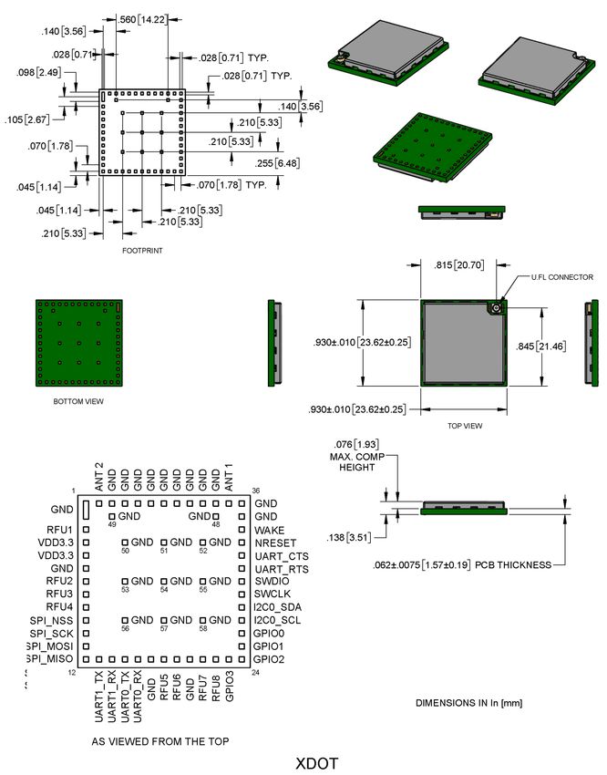
CONTENTS

        Indian Models (MTXDOT-EU1-IN1) ........................................................................................................................... 25
        South Korean Models (MTXDOT-KR1) ...................................................................................................................... 26
        Asia Pacific Models (MTXDOT-AS1) .......................................................................................................................... 26
       Battery Draw Down..................................................................................................................................................... 28
        Electrical and Timing Characteristics ........................................................................................................................ 28
        Measuring the Power Draw ...................................................................................................................................... 29
       Pin Information .......................................................................................................................................................... 30
        Pin Information ......................................................................................................................................................... 30
        Pull-Up/Down............................................................................................................................................................ 32
        LoRa........................................................................................................................................................................... 32
        Crystals/Oscillator ..................................................................................................................................................... 32
        Sleep Wake and Deep Sleep Wake Pins ................................................................................................................... 32
        Interrupt Limitations ................................................................................................................................................. 33
       xDot Pinout Design Notes ........................................................................................................................................... 34
        Serial Pinout Notes.................................................................................................................................................... 34
       Serial Settings.............................................................................................................................................................. 34
       LoRa ............................................................................................................................................................................ 34
        Throughput Rates...................................................................................................................................................... 34
        Range ........................................................................................................................................................................ 34
       Resetting the xDot ...................................................................................................................................................... 36
    Chapter 6 – Antennas ............................................................................................................................................ 37
      Antenna System ......................................................................................................................................................... 37
      U.FL and Trace Antenna Options ............................................................................................................................... 37
      LoRa Antenna .............................................................................................................................................................. 38
       LoRa Antenna Specifications .................................................................................................................................... 38
      RSMA-to-U.FL Coaxial Cables ..................................................................................................................................... 39
       Coaxial Cable Specifications ..................................................................................................................................... 39
      Ethertronics Chip Antenna.......................................................................................................................................... 40
       Antenna Specifications ............................................................................................................................................. 40
      Stackup Information.................................................................................................................................................... 40
       Developer Board Layer Stackup................................................................................................................................ 40
       Stackup Table ............................................................................................................................................................ 41
       Impedance ................................................................................................................................................................ 41
      Chip Antenna Design Guidelines................................................................................................................................. 43
       Antenna Pad Layout.................................................................................................................................................. 44
       PCB Layout ................................................................................................................................................................ 44
      Antenna Matching Network........................................................................................................................................ 45
       915 ............................................................................................................................................................................ 45
       868 ............................................................................................................................................................................ 46
      OEM Integration ......................................................................................................................................................... 46
       FCC & IC Information to Consumers ......................................................................................................................... 46

4                                                                                                                                                      xDot® Developer Guide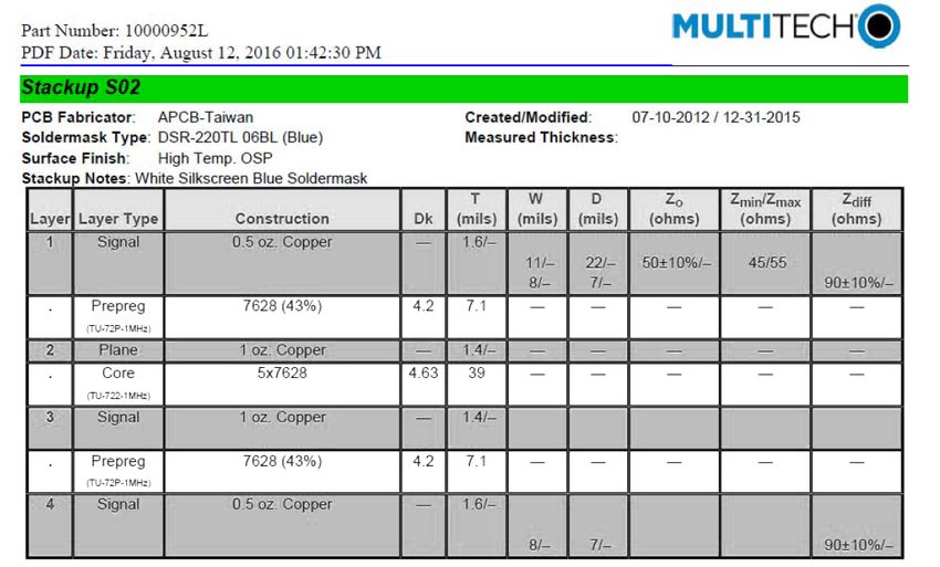
CONTENTS

      FCC Grant Notes........................................................................................................................................................ 46
     Host Labeling............................................................................................................................................................... 47
  Chapter 7 – Safety Information .............................................................................................................................. 48
    Handling Precautions .................................................................................................................................................. 48
    Radio Frequency (RF) Safety ....................................................................................................................................... 48
      Sécurité relative aux appareils à radiofréquence (RF).............................................................................................. 48
    Interference with Pacemakers and Other Medical Devices ...................................................................................... 49
      Potential interference ............................................................................................................................................... 49
      Precautions for pacemaker wearers ........................................................................................................................ 49
    Device Maintenance ................................................................................................................................................... 49
    User Responsibility...................................................................................................................................................... 50
  Chapter 8 – Regulatory Information....................................................................................................................... 51
    EMC, Safety, and Radio Equipment Directive (RED) Compliance .............................................................................. 51
    47 CFR Part 15 Regulation Class B Devices ................................................................................................................. 51
    FCC Interference Notice ............................................................................................................................................. 51
    FCC Notice ................................................................................................................................................................... 51
    Industry Canada Class B Notice................................................................................................................................... 52
  Chapter 9 – Environmental Notices........................................................................................................................ 53
    Waste Electrical and Electronic Equipment Statement .............................................................................................. 53
      WEEE Directive.......................................................................................................................................................... 53
      Instructions for Disposal of WEEE by Users in the European Union ........................................................................ 53
    REACH Statement ....................................................................................................................................................... 53
      Registration of Substances........................................................................................................................................ 53
    Restriction of the Use of Hazardous Substances (RoHS) ............................................................................................ 54
    Information on HS/TS Substances According to Chinese Standards ......................................................................... 55
    Information on HS/TS Substances According to Chinese Standards (in Chinese) ...................................................... 56
  Chapter 10 – Labels................................................................................................................................................ 57
    Label Examples............................................................................................................................................................ 57
  Chapter 11 – Developer Kit Overview .................................................................................................................... 58
    xDot Developer Kit ..................................................................................................................................................... 58
     Developer Kit Package Contents............................................................................................................................... 58
     Firmware Updates..................................................................................................................................................... 58
     Programming Devices in Production ........................................................................................................................ 58
    xDot Developer Kit Mechanical Drawings................................................................................................................... 59
    Micro Developer Board LEDs ...................................................................................................................................... 60
  Chapter 12 – Developer Board Schematics............................................................................................................. 61
    Assembly Diagrams and Schematics ........................................................................................................................... 61
     Assembly Diagrams ................................................................................................................................................... 61
     Schematics ................................................................................................................................................................ 63

xDot® Developer Guide                                                                                                                                                              5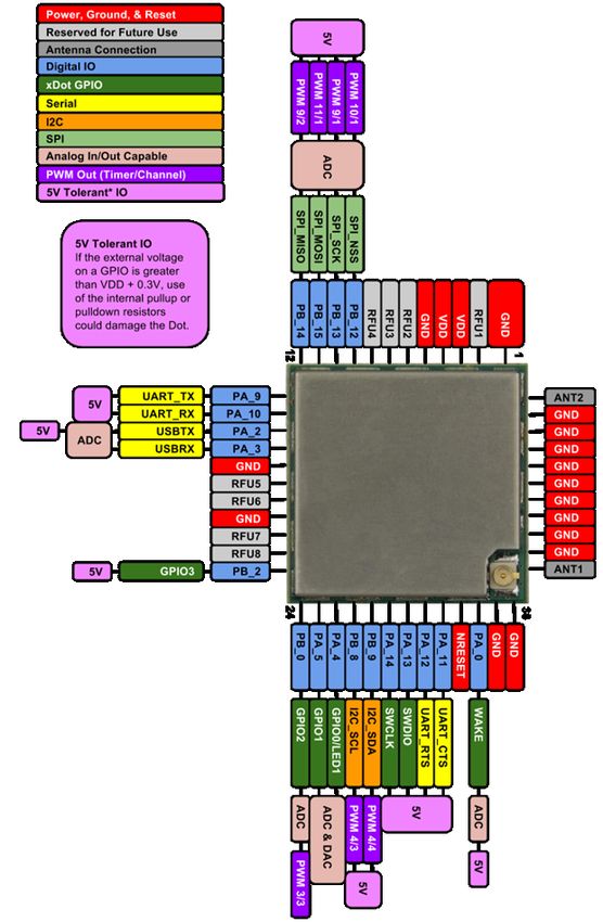
CONTENTS

    Chapter 13 – Design Considerations....................................................................................................................... 67
      Noise Suppression Design ........................................................................................................................................... 67
      PC Board Layout Guideline ......................................................................................................................................... 67
      Electromagnetic Interference .................................................................................................................................... 67
      Electrostatic Discharge Control................................................................................................................................... 68
    Chapter 14 – Mounting xDots and Programming External Targets ......................................................................... 69
      Mounting the Device on Your Board .......................................................................................................................... 69
      Solder Profile............................................................................................................................................................... 69
        Setpoints (Celsius)..................................................................................................................................................... 70
      xDot Packing ............................................................................................................................................................... 70
      In-System Programming of xDot................................................................................................................................. 70
        Schematic Example ................................................................................................................................................... 71
        Recommended Programming Hardware for Production.......................................................................................... 71
        JTAG/SWD Connector .............................................................................................................................................. 72
    Appendix A – Appendix A Release Note Archive .................................................................................................... 73
      What's New in Firmware Version 3.2 ......................................................................................................................... 73
       LoRaWAN Version 1.0.3 Class B Support .................................................................................................................. 73
       Russian Channel Plan Support .................................................................................................................................. 73
       AT Command Additions and Modifications .............................................................................................................. 73
      What's New in Firmware Version 3.3 ......................................................................................................................... 73
       LoRaWAN Version 1.0.4 Changes ............................................................................................................................. 73
       Pin Output Changes .................................................................................................................................................. 74
       AT Command Additions and Modifications .............................................................................................................. 74
      What's New in Firmware Version 4.0 ......................................................................................................................... 75
       Configuration Persistence ......................................................................................................................................... 75
       FOTA Enhancements................................................................................................................................................. 75
       AT Command Additions and Modifications .............................................................................................................. 75
    Index...................................................................................................................................................................... 77

6                                                                                                                                                  xDot® Developer Guide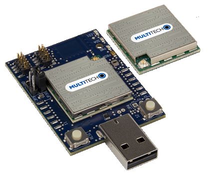
PRODUCT OVERVIEW

Chapter 1 – Product Overview
   Overview
   The MultiConnect xDot (MTXDOT) is a LoRaWANTM, low-power RF device, capable of two way communication over
   long distances, deep into buildings, or within noisy environments* using the unlicensed ISM bands in North
   America, Europe and worldwide. The xDot is a compact surface-mount device with an mbed enabled processor and
   enhanced security. The xDot features an integrated ARM® Cortex®-M3 processor and mbedTM compatible software
   library for developers to control, monitor and bring edge intelligence to their Internet of Things (IoT) applications.
   *
    Actual distance depends on conditions, configuration, antennas, desired throughput, and usage frequency. In
   dense urban environments, a typical range is 1-2 miles.

   What's New in Firmware Version 4.1
   The new release includes the following changes:
             LoRaWAN 1.0.4 Support and Regional Parameters RP2 1.0.3
               Changes to Wake Pin
               Improved boot time from Sleep Mode
               New and updated AT Commands

   LoRaWAN 1.0.4 Support and Regional Parameters RP2 1.0.3
   Adds AS923-4, extending support to Israel.

   Changes to Wake Pin
   Ability to set trigger for WAKE pin as rising, falling, or either.

   Improved Boot Time from Sleep Mode
   Reduced xDot boot time waking from deep sleep by moving scan for external flash to start of fragmentation
   session instead of at boot.

   AT Command Additions and Modifications
       Note: For AT Command details, refer to S000768 xDot AT Command Reference Guide .
          Changed AT+ERASE=1 so that it only erases the area of external flash used for FOTA if present on xDot.
          Added AT+ERASE=2 erase configuration in the EEPROM for xDot.
          Changed AT+WP added trigger parameter and mode parameter to set pullup/pulldown.
          Added AT+DUTY set duty cycle maximum or per band.
   For an archive of release notes, go to Appendix A.

   Documentation Overview
   This manual is one part of xDot documentation. Refer to the Related Documentation and mbed sections for
   additional information needed to program your xDot and integrate your application with the MultiConnect Conduit
   gateway.
   This document includes:

xDot® Developer Guide                                                                                                  7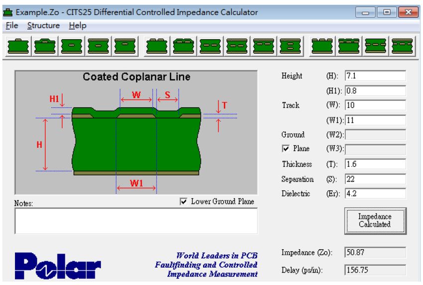
PRODUCT OVERVIEW

          xDot device information: including mechanical drawings, specifications, safety and regulatory information,
          and other device specific content.
          Developer Kit information: including design considerations, schematics, and installation and operation
          information.
    This current version of this manual is available at www.multitech.com/support.

    Related Documentation
          xDot AT Command Guide: Includes details on the AT commands available for xDots.
          MultiTech Developer Site: Application notes, LoRa information, and documentation for related products
          such as the MultiConnect Conduit (MTCDT) gateway and the LoRa accessory card (MTAC-LORA) are available
          on the MultiTech developer site. This site includes information on using the Conduit with xDots. Go to:
          www.multitech.net
          Processor Datasheet: ST ARM® Cortex®-M3 processor (STM32L151CCU6) datasheet is available on the ST
          website: http://www.st.com/resource/en/datasheet/stm32l151cc.pdf

    mbed Documentation
    ARM mbed is a free, open-source platform and operating system for embedded devices using the ARM Cortex-M
    microcontrollers. The mbed website provides free software libraries, hardware designs, and online tools for rapid
    prototyping of products. The platform includes a standards-based C/C++ SDK, a microcontroller HDK, and
    supported development boards, an online compiler and online developer collaboration tools.
       Note: To send and receive data, you need a LoRaWAN 1.0 gateway, such as MultiTech's Conduit (MTCDT) with
       an MTAC-LORA accessory card installed.

    Programming the xDot Microcontroller
       Note: To program an xDot application, you need the xDot Developer kit, which includes an xDot mounted on a
       developer board.
    Use the ARM mbed ecosystem to program the microcontroller. Compile in the cloud or locally, copy the resulting
    binary file to the mbed USB drive, and reset the xDot.
    On the xDot mbed page, MultiTech supplies source code for non-RF portions of the xDot. To comply with FCC and
    ETSI certification, some portions of the software is available only as binary libraries.
    MultiTech offers both development and stable release versions of the library.
              Development version: libmxDot-dev-mbed6
               Stable release version: libmxDot-mbed6
    You can use either the mbed online compiler or offline tools.
          Online: Use the mbed-os library in your mbed application
          Offline: Use mbed-cli tools to create, manage, and build your mbed 6.0 application.

    General mBed Links
          Explore mbed: https://os.mbed.com/
          Getting Started with mbed: https://os.mbed.com/docs/mbed-os/#gettingstarted
          mbed Handbook: https://os.mbed.com/docs/mbed-os

8                                                                                               xDot® Developer Guide
PRODUCT OVERVIEW

          mbed online compiler documentation: https://os.mbed.com/docs/mbed-os/latest/quick-start/online-with-
          the-online-compiler.html
          mbed cli documentation: https://os.mbed.com/docs/mbed-os/latest/quick-start/offline-with-mbed-cli.html
          mbed workspace tools documentation: https://os.mbed.com/docs/mbed-os/v6.1/build-tools/index.html

   xDot Platform
   The xDot mbed page includes the xDot library, firmware, and test cases
   https://developer.mbed.org/platforms/MTS-xDot-L151CC/

   EUI and Networking
   xDots have an Extended Unique Identifier (EUI). To query the device for the EUI, AT+DI:

   AT+DI=
   AT+DI=001122AABBCCDDEE
   For information on setting up xDots as part of a LoRa network, go to www.multitech.net.

   Configuration Persistence
   To safeguard your configuration, the device offers configuration persistence in the form of configuration
   redundancy and wear leveling.
      Note: These features change the configuration storage and make the firmware update a one way process. The
      configuration is not backward compatible to any version less than 4.0.x. Once a device is flashed with 4.0.x
      firmware, the configuration is converted to a new format. Any versions earlier than 4.0.x cannot parse this new
      format.
   Redundancy
   In case of data loss or corruption, your device stores multiple copies of the configuration and can fall back to the
   last good copy.
   Wear Leveling
   Wear leveling writes across the entire flash sector and skips bad sections on write failure. Frequently saved session
   parameters have more flash space available to extend the expected life of the flash system on your device.

   Differential and Compressed Upgrade Files
   Differenital and compressed upgrade files can be used to reduce the size of firmware upgrades sent over-the-air
   (FOTA). Smaller files reduce the time required to deliver an update. Smaller FOTA sessions increase end-device
   battery life.
   Creating Differential and Compressed Files
   To package application firmware binaries for Dot devices with compression or deltas, use the mtsmultitool utility.
   The output is a binary file that can be sent to the bootloader over serial YMODEM or FOTA.
   For more details on the utility, see: https://pypi.org/project/mtsmultitool/ .
   The utility requries Python v3.8 installed. To install the utility, open a command prompt and enter: pip install
   mtsmultitool

xDot® Developer Guide                                                                                                     9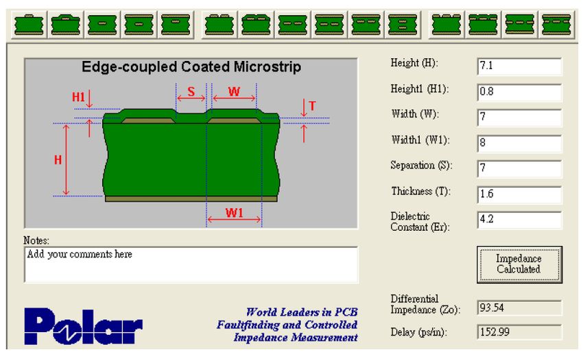
PRODUCT OVERVIEW

     Product Build Options
     Product                     Description                                              Package Quantity
     North America
     MTXDOT-NA1-A00              915 MHz LoRa Module UFL/TRC (NAM)                        1, 100, or 1000
     MTXDOT-NA1-A01              915 MHz LoRa Module TRC (NAM)                            1, 100, or 1000
     EMEA
     MTXDOT-EU1-IN1-A00          868 MHz LoRa Module UFL/TRC (EU)                         1 or 100
     MTXDOT-EU1-IN1-A01          868 MHz LoRa Module TRC (EU)                             100
     Australia
     MTXDOT-AU1-A00              AU915 MHz LoRa Module UFL/TRC (AU)                       1 or 100
     MTXDOT-AU1-A01              AU915 MHz LoRa Module TRC (AU)                           100
     AS923
     MTXDOT-AS1-A00              AS923 MHz LoRa Module UFL/TRC (APAC)                     1 or 100
     Korea
     MTXDOT-KR1-A00              KR920 MHz LoRa Module w/LBT UFL/TRC (KR)                 1 or 100
     Developer Kits
     MTMDK-XDOT-NA1-A00          MultiConnect xDot Micro Developer Kit - Includes a 915 MHz xDot
     MTMDK-XDOT-EU1-IN1-A00      MultiConnect xDot Micro Developer Kit - Includes a 868 MHz xDot
     MTMDK-XDOT-AU1-A00          MultiConnect xDot Micro Developer Kit - Includes a AU915 MHz xDot
     MTMDK-XDOT-AS1-A00          MultiConnect xDot Micro Developer Kit - Includes a AS923 MHz xDot
     MTMDK-XDOT-KR1-A00          MultiConnect xDot Micro Developer Kit - Includes a KR920 w/LBT MHz xDot

       Note:
                 The complete product code may end in .Rx. For example, MTXDOT-NA1-A00.RxMTXDOT-EU1-IN1-
                 A00.RxMTXDOT-AU1-A00.RxMTXDOT-AS1-A00.RxMTXDOT-JP1-A00.Rx, where R is revision and x is
                 the revision number.

10                                                                                       xDot® Developer Guide
GETTING STARTED
Chapter 2 – Getting Started
Getting Started with the xDot Developer Kit
Getting started depends on what you want to do. By default, xDot ships with firmware that supports AT
Commands that use the serial I/O. For AT Commands, refer to the separate MultiConnect Dots AT Command
Reference Guide.
Two serial interfaces are available through the USB interface, one is used to send AT commands to the xDot and
the other is for debug messages. Refer to Chapter 4, Specifications and Pin Information for information on which
pins are available out of the box.
Before starting your project development, make sure you have the latest firmware for the Developer Kit and xDot.
Go to the xDot mbed page for firmware. https://developer.mbed.org/platforms/MTS-xDot-L151CC/
To send commands to the xDot:
1. Plug the developer board into a USB port.
2. Open communications software, such as TeraTerm, Putty, or Minicom.
3. Set the following:
Baud rate = 115,200
Data bits = 8
Parity = N
Stop bits = 1
Flow control = Off
To develop using Mbed, the xDot Mbed page includes libraries and test cases. Refer to mbed Documentation for
details and links.
For help setting up a MultiConnect® Conduit® to send data to and from an xDot, refer to Related Documentation .
COM Port Enumeration by Operating System
xDots create an AT Commands port and a debug port.
Linux
The following COM ports are created on Linux systems:
/dev/ttyACMx
/dev/ttyACMy
Where x and y may be 0 and 1, 3 and 4, etc.
The COM port with lower number is the AT command port and COM port with the higher number is the debug
port.
Windows
On Windows systems, COM ports appear in the Device Manager:
Debug Port: Mbed Serial Port
xDot® Developer Guide 11GETTING STARTED
AT Command Port: XR21V1410 USB UART
You may need to install a driver for the debug port to function properly. Go to:
https://developer.Mbed.org/handbook/Windows-serial-configuration
Mac
On Mac systems, COM ports appear in the Device Manager as:
/dev/cu.usbmodemx
Where x is a string of numbers and possibly letters, ending in a number.
The COM port with lower number is the AT command port and COM port with the higher number is the debug
port.
Updating Firmware Using the xDot Bootloader
The xDot bootloader allows firmware upgrades either via YMODEM through command or debug serial ports at
115,200 bps.
To enter the bootloader, enter the characters xdt on either serial port upon processor reset. The bootloader allows
250ms for x and then 500 ms each for d and t. If these timers expire before receiving the proper character or
another character is received, the bootloader jumps to the application code.
The bootloader includes an option to upgrade application code via YMODEM or jump to the application
code. During the YMODEM file transfer, the new application is programmed directly into the STM32L151CC
flash memory.
Since the new application is directly programmed into the STM32L151CC flash memory and the xDot has no
on board memory to back up the old application, recovery from failed download is the responsibility of the
host system.
The Mbed build process creates two files when building for the bootloader. The
name_of_program_application.bin file is the application with the correct offset that can be transferred via
YMODEM onto the xDot using the bootloader. The name_of_program.bin file is the entire program with the
bootloader than can be flashed on using jtag (this file cannot be transferred onto the xdot via YMODEM).
To build xDot firmware with the bootloader, you must include the bootloader.bin file in the Mbed-os directory
along with an Mbed_app.json file that includes directives describing the space used for the bootloader and the
location where the bootloader.bin file resides.
Note: For an application to run at the correct offset, it needs location where it will reside so the vector
table is correct.
Mbed-os version 5.5.4, includes hooks that allow you to easily add a boot loader for the xDot. Go to
https://docs.Mbed.com/docs/Mbed-os-handbook/en/latest/advanced/bootloader/ for details.
For the bootloader, create a file with the following content. (Actual size may vary, but needs to
accommodate the bootloader size.) Name the file Mbed_app.json and place it in the root directory.
{
"target_overrides": {
"XDOT_L151CC": {
"target.restrict_size": "0x8000"
}
}
12 xDot® Developer GuideGETTING STARTED
}
For the application, create a file with the following content. Name it Mbed_app.json and place it in the root
directory.
{
"target_overrides": {
"XDOT_L151CC": {
"target.bootloader_img": "bootloader_location/bootloader.bin"
}
}
}
xDot® Developer Guide 13FOTA
Chapter 3 – FOTA
External Flash Components for FOTA
AT firmware on the xDot supports FOTA when a compatible external flash component or block device is connected
to the xDot. In this configuration, multicast and fragmentation sessions are managed by the xDot. Messages for
multicast (port 200) and fragmentation (port 201) are handled by the xDot and are not passed through to the AT
terminal.
File space is statically allocated. There is no traditional file system. The xDot will reserve space for new application
firmware, a backup of the current application, and an upgrade result file. A total of 436 KB (0x6A000 bytes) of free
space is required.
External Flash Component Requirements
For a flash component or block device to work with the xDot, it must meet the following criteria:
Work with MBed OS DataFlashBlockDevice or SPIFBlockDevice classes
Maximum 4 KB sector erase size
Maximum 512 byte page size
SPIF type components must support Serial Flash Discoverable Parameters (SFDP)
External Flash Components Tested for Compatibility
Part Number Type Manufacturer Density Page Size Erase Size
MX25R8035 SPIF Macronix 8 MB 512 bytes 4 KB
AT45DB041E DATAFLASH Adesto 4 MB 256 bytes 2 KB
Host MCU
When no external flash component is present, fragmentation messages (port 201) must be handled by a host MCU
implementing the Fragmented Data Block Transport.
FOTA (FUOTA) Overview
This requires xDot firmware Version 4.0 or higher and a Conduit® with AEP (mPower) 5.2 or higher.
Firmware Over the Air (FOTA) also known as Firmware Upgrade Over the Air (FUOTA) is a way to upgrade Dot end
devices using multicast and file fragmentation packages defined in the LoRaWAN specification. FOTA allows the
14 xDot® Developer GuideFOTA
Conduit to update the firmware on many Dots at once using multicast and error correction packets. FOTA is still in
its early stages of revision and does have potential problems, which are included in this topic.
Note: FOTA is enabled by default.
To start the FOTA process, the Conduit sends two setup downlinks to the Dot. First, the Conduit then sends a
multicast session setup request to the Dot. The Dot responds with a multicast session setup answer. The Conduit
sends a fragmentation setup request. The Dot responds by sending back a fragmentation setup answer. Once
setup is complete, the Dot waits until the start of the multicast session. At the start of the session, the Dot
switches to class C with the specified data rate and frequency to receive the file fragments sent by the Conduit.
After the file fragments are sent, the Conduit starts sending parity fragments. At any point when the Dot is able to
reconstruct the firmware file, the CRC is calculated and the CRC message id sent in Class A. This could happen any
time after the last fragment is sent to after the last parity is sent.
For details on the FOTA AT Commands, go to xDot AT Command Reference Guide (S000768).
FOTA Stages
A FOTA session has four stages: 1) session setup, 2) fragmentation, 3) parity, and 4) verification.
Session Setup
For a multicast session to work with class A devices, a start time must be agreed upon by the network server and
each device. This requires the devices to synchronize their time with the server. These critical tasks are done
during session setup.
Class A devices must periodically send uplinks to open downlink windows making the time required to complete an
operation setup directly tied to the frequency of device uplinks. For each device involved in the operation, some
extra time should be added to the total setup time to account for latency in queuing each device’s message.
Setup messages are sent up to 3 times. Worst-case timing for operation setup would be ((3 * device_uplink_period
* 2) + (overhead * number_of_devices)).
The included diagram illustrates the events that occur during a best-case setup with no messages missed and well-
timed device uplinks. Each device follows these steps:
1. FOTA operation queues Multicast setup message with network server.
2. Device sends an uplink.
3. Multicast setup message is downlinked to the device.
4. Device sends a multicast setup response.
5. FOTA operation queues fragmentation setup message.
6. Device sends an uplink.
7. Fragmentation setup is downlinked to the device.
8. Device sends a fragmentation setup response from device.
xDot® Developer Guide 15FOTA
Fragmentation
During this stage, the device should only send uplinks as necessary, too many can cause excessive fragment loss.
Applications on the device should not perform heavy processing activities during FOTA. Doing so can cause
fragments to overlap and excessive fragment loss. The number of fragments required to send a file depends on the
Data Rate. The device clears the file system to ensure enough free space to save update firmware and a backup
copy of the current firmware saved by the bootloader. User files are removed when the fragmentation session is
set up.
Parity
Multicast messages are unconfirmed meaning some loss of fragments is expected. The device can recover a certain
number of fragments though parity.
16 xDot® Developer GuideFOTA
The xDot can tolerate up to 150 lost fragments.
Verification
Once a device completes its fragmented file, it calculates a CRC64 and sends a request to the server to verify the
CRC. The server sends a response indicating if the CRC matches or not. If the CRC is verified the device reboots and
performs the upgrade. If the CRC does not match, the downloaded file is discarded.
Potential Problems
If the Dot misses either setup message, the FOTA session will not be successful. The Dot attempts to receive
both messages multiple times. If the Dot is unsuccessful, it resets the fragmentation sessions and multicast
session.
If the Dot does not receive a CRC response from the Conduit, it resets the fragmentation and multicast
sessions and deletes the fragmentation file.
The Dot can reset the multicast/fragmentation session at any time using AT+FOTA=2.
When using AT+SLEEP, make sure to wake up the Dot before a scheduled FOTA session. Using AT+FOTA=3
will return the time in seconds before the FOTA session is scheduled to start.
If AT+SLEEP is used during the FOTA session, the Dot will miss packets and the session will likely fail.
The FOTA session sends down packets every 1.5 seconds (assuming no duty cycle) and parity packets every
3 seconds by default. For best results, Multitech recommends users suspend all normal Dot operations until
the FOTA session is complete.
Troubleshooting FOTA
Troubleshooting FOTA on the Dot
Problem: Dot does not receive any file fragments.
Troubleshooting:
The Dot must receive two setup messages for the FOTA session to work, fragmentation setup request
and multicast setup request.
Verify if the Dot received the fragmentation setup request. This comes down on port 201. When the
Dot receives this request, it sends an answer. Check the Dot debug log for Sending Fragmentation
Response.
After sending the fragmentation response, the Dot receives a multicast setup request. Check for this
message on port 201. The Dot responds with a multicast setup answer. Check the Dot debug log for
Sending Multicast Response.
Make sure the Dot is in Class C at the start of the FOTA session (AT+DC). The Dot must also be awake
and will not wake up to start the FOTA/Multicast session. The command AT+FOTA=3 displays the time
before a FOTA session starts.
Make sure the Conduit is sending the fragments by checking the Conduit logs in /var/log/log_fota*.
Problem: Dot cannot complete the FOTA session.
Troubleshooting:
If the Dot misses too many packets, the FOTA session cannot be completed.
xDot® Developer Guide 17FOTA
If the Dot was able to reconstruct the file using parity fragments, it sends a CRC check to the Conduit.
Check the Dot debug log for Sending CRC. If the Dot does not receive a response or the Conduit
responds with CRC not correct, the Dot discards the file.
Problem: Dot fails to process parity fragments.
Troubleshooting:
If the Conduit sends parity fragments faster than the Dot can process them, the Dot starts failing to
properly receive the fragments. This results in failed MIC checks or wrong address, which is noted in the
Dot debug log.
To correct this, increase the delay between parity fragments on the Conduit.
Problem: Dot is unexpected state.
Troubleshooting:
If the Dot is in a bad or unknown state, use ATZ to reset the Dot and clear the multicast and FOTA
states. AT+FOTA=2 also resets FOTA and Multicast states.
Troubleshooting FOTA on the Conduit
Problem: FOTA Session not starting.
Troubleshooting:
Verify that there is not a current FOTA session. If there is no current FOTA session and a FOTA session
will not start, reboot the Conduit.
If the Conduit does not receive at least one response from an Dot, the FOTA session will not start. The
process will go from SETUP (10%) to TEARDOWN (90%). Check the log (/var/log/log_fota*) to make sure
the Conduit is receiving the setup answers.
Problem: FOTA Session not successful.
Troubleshooting:
For a FOTA Session to be successful, the Dot has to be able to reconstruct the file. If the Dot misses too
many packets, the FOTA session will not be successful and the Dot will not send a CRC to the Conduit.
If the Conduit receives a CRC from an Dot check the FOTA log (/var/log/log_fota*) to make sure the CRC
matches the Conduit and the CRC correct answer is sent back to the Dot. Check the Dot debug log to
verify if the device received the CRC answer.
Problem: Stop FOTA Session / FOTA Session won’t start (FOTA in progress) / Stop Multicast Session
Troubleshooting:
To end a FOTA session that is in progress, send 'ps -A | grep fota'. Find the PID associated with lora-fota
(not lora-fota-demo). Then send 'kill (pid of lora-fota)'.
Also send 'rm -r -f ~/.fota/'. Devices may be in Class C or Class A depending on the FOTA session status
before it ended. Make sure to change the devices back to their appropriate class. Make sure the FOTA
daemon is running by '/etc/init.d/fotad restart'.
18 xDot® Developer GuideFOTA
To end a Multicast session that is in progress, use 'ps -A | grep mcm'. Find the PID associated with lora-
mcm. Then use 'kill (pid of lora-mcm)'. Also send 'rm -r -f ~/.fota/'.
Wiping out the .fota directory removes any future FOTA/multicast sessions scheduled that have not
setup.
xDot® Developer Guide 19MECHANICAL DRAWINGS WITH PINOUTS
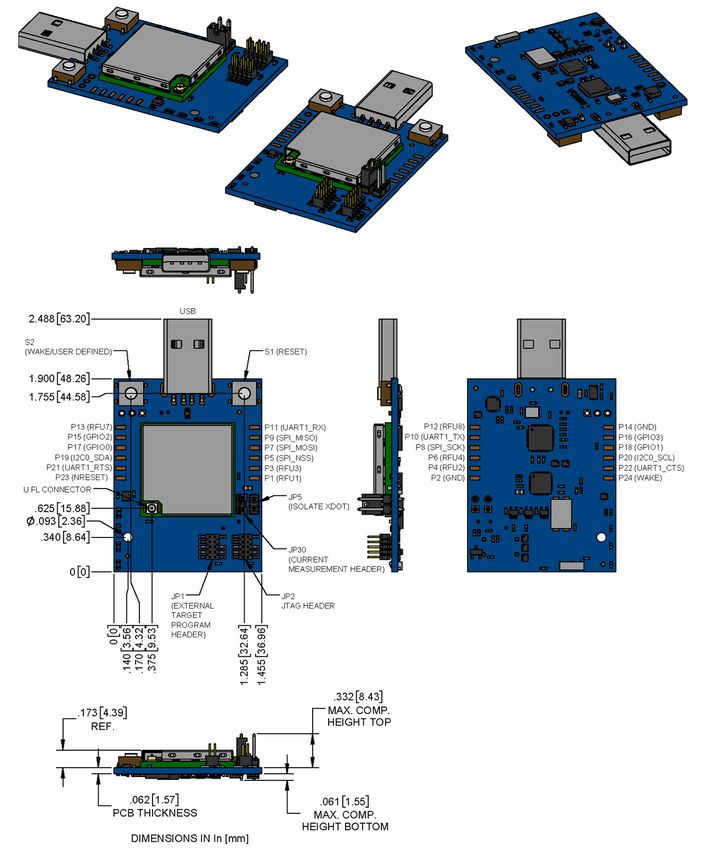
Chapter 4 – Mechanical Drawings with Pinouts
xDot
Note: The xDot development board uses a land pattern that matches the xDot land pattern in the previous
image. All pads are 0.028 inches square except the large one, which is 0.098 inches x 0.028 inches.
20 xDot® Developer GuideSPECIFICATIONS AND PIN INFORMATION
Chapter 5 – Specifications and Pin Information
MTXDOT Specifications
Category Description
General
Compatibility LoRaWAN 1.0.4 specifications
Interfaces Note that pin functions are multiplexed.
Up to 19 digital I/O
Up to 10 analog inputs
2 DAC outputs
I2C
SPI
Wake pin
Reset pin
Full UART
mbed/simple UART (RX & TX only)
mbed programming interface
CPU Performance
CPU 32 MHz
Max Clock 32 MHz
Flash Memory 256 KB, with xDot library 136 KB available; with AT firmware, 56 KB available
EEPROM 8 KB, available 6 KB
SRAM 32 KB
Backup Register 128 byte, available 88
Physical Description
Weight 0.0001 oz. (0.003g)
Dimensions Refer to Mechanical Drawings for Dimensions.
RF Connectors
-UFL Models U.FL
-TRC Models Trace Connection
Environment
Operating Temperature -40° C to +85° C
Storage Temperature -40° C to +85° C
Humidity 20%-90% RH, non-condensing
xDot® Developer Guide 21SPECIFICATIONS AND PIN INFORMATION
Category Description
Power Requirements
Operating Voltage 2.4 to 3.57 V
North American Models (MTXDOT-NA1)
Category Description
Radio Frequency
ISM Bands US902-928 MHz
Certifications and Compliance
EMC US: FCC Part 15 Class B
Canada: ICES-003
Radio FCC 15.247:2015
FCC 15.109:2015
FCC 15.107:2015
Safety UL 60950-1 2nd ED
cUL 60950-1 2nd ED
Transmission
Max Transmitter Power Output (TPO) 19 dBm
Maximum Receive Sensitivity -130 dBm
1
Link Budget 147 dB Point-to-Point
145 dB Point-to-Multipoint
Max Effective Isotropic Radiated 36 dBm
Power (EiRP)
Deep Sleep Current < 2 uA
Category Description
Receive Sensitivity
Spreading Factor North America 2
6 -111 dBm
7 -116 dBm
8 -119 dBm
9 -122 dBm
10 -125 dBm
11 -127 dBm
12 -129 dBm
22 xDot® Developer GuideYou can also read