Zehnder Comfosystems Heat and Energy Recovery Ventilation - Installation Manual - HubSpot
←
→
Page content transcription
If your browser does not render page correctly, please read the page content below
Installation Manual

Zehnder Comfosystems
Heat and Energy
Recovery Ventilation
                                    Version 2 - 8/16/2018
            For the most current update of this manual visit zehnderamerica.com.
8/16/2018
ii   For the most current update of this manual visit zehnderamerica.com.
Zehnder Balanced Ventilation:
        The Heart of a Healthy Home

         Health

         • Reduces health risks associated with asthma, allergies and other
           respiratory diseases.
         • Maintains peak concentration and energy by reducing CO2 levels.
         • Reduces VOCs and other indoor air pollutants with continuous
           ventilation.

         Comfort

         • Delivers a constant supply of fresh filtered air without extra noise or
           drafts.
         • Helps maintain temperature and humidity levels for maximum
           comfort.
         • Replaces stale, smelly air with fresh, filtered outside air.

         Energy Efficiency

         • Operates with ECM motors for very low power consumption.
         • Saves on heating and cooling with up to 90% efficient heat recovery
           ventilation.
         • North America’s only residential HRV/ERVs certified by the
           Passive House Institute.

         Ease of Installation

         • Designed as a complete system with all the necessary distribution
           components.
         • Requires few tools and minimal expertise due to the modular,
           quick-connect format.
         • Allows for easy duct runs in interior walls and joist bays with small,
           flexible duct options.

         Fit and Finish

         • Blends neatly into interiors with low-profile diffusers and paintable
           metal grilles.
         • Provides flexible design options to meet varying aesthetic
           requirements.
         • Stays clean with simple lines and durable powder coat finishes.

                                            8/16/2018
               For the most current update of this manual visit zehnderamerica.com.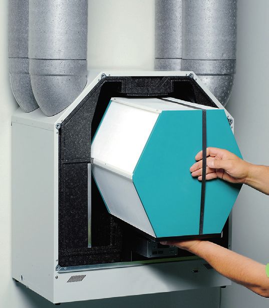
8/16/2018
For the most current update of this manual visit zehnderamerica.com.
Table of Contents

A SYSTEM OVERVIEW
ComfoAir System Components.................................................. 2
Introduction.............................................................................. 3
ComfoAir System Overview....................................................... 4
ComfoWell System Components............................................... 5
Zehnder Ducting...................................................................... 6
Supply and Return Registers..................................................... 7
Zehnder Controls..................................................................... 8
Zehnder Filters......................................................................... 9
Optional Preheaters................................................................ 10

INSTALLATION
Installation Sequence...............................................................11
Unit Location..........................................................................12
Exterior Grilles Installation................................................... 13-14
Ducting Between Exterior Grilles and HRV/ERV..........................15
Installation of Zehnder ComfoPipe.............................................16
ComfoPipe Connections to HRV/ERV........................................17
Determining Register Box Locations..........................................18
Mounting TVA Register Boxes...................................................19
Mounting CLD Register Boxes..................................................20
ComfoWell Distribution Components................................... 21-26
Remote-Mounted Silencer/Manifold Assemblies.........................27
Installing Interior Ducting from Manifolds to Registers............. 28-31
Mounting the HRV/ERV Units....................................................32
Installing Finish Diffusers and Grilles.................................... 33-34
Installing the Waterless P-Trap............................................. 35-41
Completing the Installation........................................................42

ELECTRICIAN INFORMATION
Rough-In.......................................................................... 43-44
Finish............................................................................... 45-46
Wiring Diagrams................................................................ 47-19

                                                              8/16/2018
                                 For the most current update of this manual visit zehnderamerica.com.   1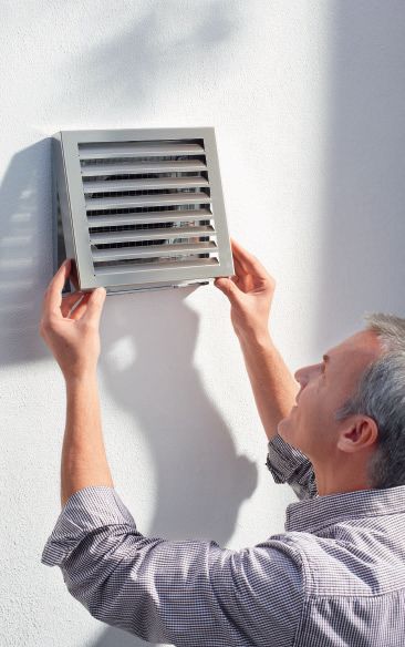
Zehnder ComfoAir System Components

                                                                                Register boxes provide
                                                                                terminations for one, two,
    ComfoFlex is a Zehnder                                                      or three 3” ComfoTube
       proprietary 3” flexible                                                  ducts, as needed, and
    duct that can be routed                                                     a variety of diffusers and
    through 2x4 stud walls.                                                     grilles may be selected to
     It connects to Zehnder                                                     provide the correct
         distribution compo-                                                    airflow with adjustability.
       nents with our unique
      twist-connect system.
                                                                                                                                           Stainless steel exterior
                                                                                                                                           grilles for intake and
                                                                                                                                           exhaust are fitted with
                                                                                                                                           durable wire mesh
       ComfoWell manifold/                                                                                                                 varmint guards and
    mounting plates enclose                                                                                                                gasketed duct
       the silencer box and                                                                                                                connections.
            provide multiple
     home-run connections
      for the 3” ComfoTube
                    ducting.

         ComfoWell silencer
     boxes on both the sup-                             Programmable controllers provide a                    ComfoPipe insulated
     ply and return air sides                          basic user interface as well as access                 duct connects the HRV/
         attenuate fan noise                             to the system’s advanced features                    ERV to the exterior
       as well as room noise                               to enable continuous balanced                      air. The rigid foam
          within the system.                             ventilation with normal, boost, and                  construction provides
        Optional filter casing                          away modes. Additional options are                    an airtight, insulated
       modules may also be                             available such as boost switches and                   conduit that eliminates
      mounted to the supply                                     CO2 and RH sensors.                           condensation inside
                  air silencer.                                                                               conditioned space.
                                                                                                              90 degree elbows
                                                                                                              and sleeves allow for
                  ComfoWell mounting                                                                          various configurations.
                    kits and end plates
               provide varying options
                for connecting the dis-
              tribution components to
                the HRV/ERV; silencer/
               manifold boxes may be
              mounted directly on the
                       unit or remotely.

                                                                                                                                           Highly efficient Heat
                                                                                                                                           Recovery Ventilators
                     Removable filters                                                                                                     and Energy Recovery
                 protect the HRV/ERV                                                                                                       Ventilators provide
                      core and can be                                                                                                      fresh air while reducing
                    vacuumed clean or                                                                                                      energy costs.
                 replaced as needed.
                Filters are available in
                          MERV 7/8 or
                             MERV 13.

                                                                                                                                        HRV and newer model
                                                                                                                                        ERV cores are removable
                                                                                                                                        for inspection and easy
                                                                                                                                        washing.

                                                                            “Waterless” p-traps are
                                                                          installed for condensation
                                                                           drainage; airtightness is
                                                                          maintained even when no
                                                                             water is in the p-trap

                                                                        8/16/2018
2                                          For the most current update of this manual visit zehnderamerica.com.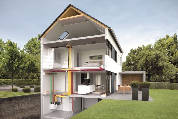
Introduction
This guide is intended to be more or less universal for North
American applications. However, it must be understood that con-
struction methods and site situations vary greatly from installation
to installation such that it is not possible to cover every single
contingency that may occur.

However, every effort is made while designing the Zehnder system to
take different construction methods and site conditions into account
in the customized quotes provided by the technical sales engineers
for your project. These instructions therefore are intended to cover
as many different situations as possible in the space allowed and to
provide sufficient guidance for the qualified installer to install a
properly designed Zehnder ventilation system.

This guide is intended to be used as a reference rather than a
definitive set of job specific instructions - with critical aspects of
the system design, installation, and operation highlighted in the
instructions where appropriate.

All installations of Zehnder Ventilation systems should be
performed by competent construction professionals
according to local building standards and codes.

  Zehnder Whole House System Showing Air Circulation.
    Fresh Conditioned Air
                                                                            Balanced ventilation extracts stale air from
    Return Air
                                                                            bathrooms and kitchen and supplies fresh air
    Fresh Outside Air                                                       to bedrooms and other living spaces.
    Exhaust Air

                                                         8/16/2018
                            For the most current update of this manual visit zehnderamerica.com.                           3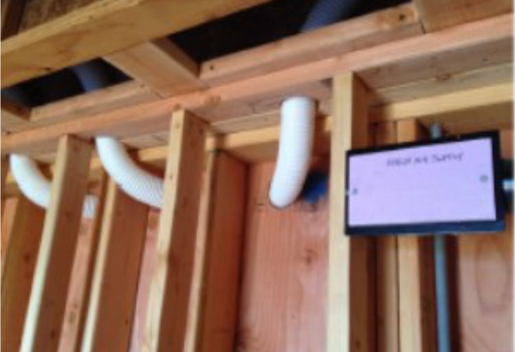
The Zehnder ComfoAir System Overview
    Zehnder ventilation systems consist of some combination of the
    following major components:
                                              • The HRV core is made up of hundreds of layers of thin plastic channels through which the
                                              supply and exhaust air streams flow.

    HRVHeat Recovery Ventilator •               Heat is transferred across the thin plastic barriers from one air stream to the other as they
                                              pass through the adjacent channels.
                                              • Supply and exhaust air streams are physically separated, avoiding
                                              cross-contamination.

                                             • The ERV core is made up of hundreds of layers of semi-permeable
                                             membrane that form channels for the air streams.

    ERV Energy (or Enthalpy)
        Recovery Ventilator
                                             • Both heat and humidity are Transferred across the membranes from
                                             one air stream to the other.
                                             • Used to reject outdoor humidity in humid climates and/or to pre-
                                             serve indoor humidity in very dry climates.

    Zehnder Comfosystems Ventilators
        ComfoAir                ComfoAir                                ComfoAir                              ComfoAir
            160                     200                                     350                                   550

    Centralized HRV/ERV.     Centralized HRV/ERV.                  Centralized HRV/ERV.                  Centralized HRV/ERV.
    48 cfm (72 boost).       72 cfm (108 boost).                   110 cfm (165 boost).                  200 cfm (300 boost).
    Vertical or horizontal   Vertical or horizontal                Vertical mounting on                  Vertical mounting on
    mounting options.        mounting options.                     wall or stand.                        wall or stand.
                                                                   Optional geothermal                   Optional geothermal
                                                                   heat exchanger                        heat exchanger
                                                                   available.                            available.

                                                           8/16/2018
4                             For the most current update of this manual visit zehnderamerica.com.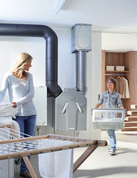
Zehnder ComfoWell Components:
Silencers and Manifolds
Zehnder’s modular approach to assembling the system allows
                                                                                                  Silencers
for many different configurations to suit each project’s unique
requirements. The complete line of manufactured components                                        CW-S 520

means every installation can be clean and professional looking
and function as designed without air leaks.

The ComfoWell air distribution components serve                                                   (other sizes
                                                                                                  available)
four main purposes:
1. To silence the sound of air distribution with the CW-S (ComfoWell Silencer).
2. To provide a connection to the HRV/ERV with the CW-P (ComfoWell End Plate) or
                                                                                                  End Plates
   CW-K (ComfoWell Mounting Kit).
3. To provide connections to the 3” ComfoTube or ComfoFlex ducts with the                         CW-P 520
  CW-M (ComfoWell Manifold).
4. To provide the option of additional filtration with the CW-F (ComfoWell Filter Casing).

ComfoWell components are available in the following sizes…
                                                                                                  (other sizes
• “520” for distribution to 10 tubes                                                              available)
• “320” for distribution to 6 tubes
• “220” for distribution to 4 tubes

                                                                                                 Mounting Kits
ComfoWell components are modular, and can be separated by trunk lines (fig A) or assembled
and mounted together (fig B) as suits the installation.                                           CW-K 520

 Figure A
 Separated                                                                                        (other sizes
                                                                                                  available)

                                                                                                  Manifolds
                                                                                    Figure B
                                                                                                  CW-M 520
                                                                                    Stacked

                                                                                                  (other sizes
                                                                                                  available)

                                                                                                  Filter Casings
                                                                                                  CW-F 520

                                                                                                  (other sizes
                                                                                                  available)

                                                                    8/16/2018
                                       For the most current update of this manual visit zehnderamerica.com.        5
Zehnder ComfoPipe: Insulated Ducting
                                              • Connects the Zehnder HRV/ERV to the exterior of the building for
                                                Outside Air intake and Exhaust Air.
                                              • Rigid foam duct prevents condensation and is easily cut to length.
                                              • Each piece is 39” long and is supplied with a sleeve for coupling to
                                                additional pieces or to elbows.
                                              • 90 degree elbows are supplied with a sleeve and may be cut into
                                                two 45 degree elbows.
                                              • Additional sleeves may be ordered.
                                              • Stainless steel exterior grilles include a wire mesh varmint guard and
                                                a gasketed nipple that fits inside the ComfoPipe ducting.
                                              • ComfoPipe is supplied in 125mm, 150mm, 160mm, and 180mm
                                              inside diameters depending on system airflow requirements.

    Zehnder ComfoFlex
                                              • ComfoFlex is a proprietary, UL listed option for interior ducting (this
                                                is not typical flex duct).
                                              • When installed according to instructions, ComfoFlex meets the same
                                                or better airflow performance characteristics as ComfoTube.
                                              • ComfoFlex ducting is 3¼” outside diameter and is ordered in lengths
                                                of 210 feet (three 70’ sections).
                                              • Shorter lengths of ComfoFlex may be spliced together as necessary.
                                              • Airtight connections are made to manifolds and diffuser boxes by
                                                threading the spiral profile onto the twin connector fitting and sealing
                                                with foil tape rated as UL-181a.

                                               Code Requirements for Ducting

                                                 HDPE plastic ComfoTube ducting is not accepted
    Zehnder ComfoTube:                           by all building officials. Be certain you understand
                                                  the code requirements of your local jurisdiction

    Inside Air Ducting                                      before installing any duct work.
                                                         Samples and specifications for both
                                                   ComfoTube and ComfoFlex are available from
                                                  Zehnder America to assist you in evaluation and
                                                        planning before you begin installation.

                                              • Double walled plastic tubing includes a strong, flexible outer layer
                                                and smoother inner layer.
                                              • Designed to minimize air losses and installation time.
                                              • 3” outside diameter is easily run through 2x4 interior walls.
                                              • Each roll of ComfoTube is 162.5 ft long, may be cut to length, and
                                                includes a sleeve for splicing shorter pieces together.
                                              • ComfoTube is connected to manifolds and diffuser boxes using the
                                                tubing’s exterior ridges to secure an O-ring for air-tightness and to
                                                receive a mounting clip for locking in place inside the bayonet fitting.

                                        8/16/2018
6          For the most current update of this manual visit zehnderamerica.com.
Zehnder Supply And Return Registers
Zehnder Comfosystems include a range of registers with
diffusers and grilles that complete the modular installation
approach, ensuring ease of installation, high performance, and Zehnder CLD Boxes with Roma Grilles
aesthetic options. Round or rectangular options are available
for both supply and return points to meet every project’s design
requirements.
CLD - 2T Register Box
• Rectangular register box. CLD-2T
• Suitable for wall or ceiling installation. (2 port, twist-connect)
• Shallow enough to fit between 2x4 studs.
• Can be connected to either 1 or 2 ComfoTube or ComfoFlex ducts.
• Fitted with Roma grill (fixed 6-1/4” x 10-1/4” grill; no adjustable diffuser).
• Roma grilles are available in either white or stainless steel finish.
• May be used for either supply or return (stainless Roma grill recommended if exhausting in
humid locations like shower rooms).
Roma Grill
• When used as a return register, a CLD filter must be installed in the box, behind the Roma grill.
(white finish)
• If adjustments to air flow are required during commissioning, a ComfoSet damper must be
installed (this is done by the commissioning agent, not by the system installer).
TVA - 2T and - 3T Register Boxes
• Register box with 5” diameter port for diffuser and 3” diameter ports for ComfoTube or
Roma Grill
ComfoFlex ducts.
(stainless finish)
• 5” port an be cut to length to be flush with room finish
• Primarily for ceiling installation, but may be installed in a thicker wall, soffit or chase.
Zehnder TVA Boxes with Diffusers/Grilles
• Can be connected to either 1, TVA-2T, or TVA-3T ComfoTube or ComfoFlex ducts.
• May be fitted with any of the following diffusers:
• STB-1 or STB-2 diffusers (for return only; adjustable airflow)
• Luna Supply diffuser (for supply only; adjustable airflow)
• Venezia grill, white (primarily for supply; may be used for return in dry locations; fixed grill
with no adjustable airflow; commissioning agent may adjust airflow with ComfoSet damper)
• When used as a return register, both STB and Venezia type diffusers must be installed with
a 125mm cone filter.
TVA-2T TVA-3T
Selecting Register Boxes and Diffusers (2 port, twist connect) (3 port, twist connect)
Select wall or ceiling location, depending on:
• Locations of thermal/air barriers
• Possible duct routes
• Minimizing duct length
• Aesthetic preferences
Select register box and diffuser/grill type, depending on:
• Ceiling or wall installation (proper framing depth) Supply-Luna Return—STB
• Supply or return
• Aesthetic preferences
• Ease of airflow adjustment during commissioning
Venezia Grill (white only)
8/16/2018
For the most current update of this manual visit zehnderamerica.com. 7Zehnder Controls ComfoSense 67 Controller
Zehnder offers a range of controls that give
access to all the innovative features built into
every ComfoAir HRV/ERV. Systems can be set
up to run very simply with minimal adjustment
or with advanced controls to vary the operation
based on a number of parameters.
Zehnder ComfoSense 67 Controller
• Included with every system sold by Zehnder America.
• Hard-wired to the unit with shielded low-voltage cable.
• Often located in the living space, but may be installed in the
mechanical space as well.
• Includes both manual and auto modes.
• Manual mode provides easy selection of low, medium and high
fan speeds. Wired Boost Switch
• “Away” mode may also be selected (very low fan speed).
• “Party” mode may be selected to run the system at high fan speed
for a few hours at a time.
• More advanced “auto” mode may be used to configure scheduled
programs to adjust fan speeds.
• Advanced menus may be accessed during commissioning to
establish baseline system settings.
Wired Boost Switches
• Installed in every toilet and/or shower room.
• May be installed in other spaces where immediate boost control is
desired.
• Simple, one-touch switch that initiates a boost period (high fan
speed).
• Duration of the boost period may be set through a menu using the
ComfoSense controller.
CO2 Sensor
• Hard-wired to the unit with low-voltage cable.
• Single-pole, momentary contact switch.
CO2 Sensor
• Designed to monitor room CO2 levels.
• Signals the HRV/ERV to adjust fan speeds based on CO2 levels
using 0-10v input.
• LEDs on the sensor indicate CO2 level and current ventilation
level.
• Hard-wired to the HRV/ERV with shielded, low-voltage cable.
Relative Humidity (RH) Sensor
• Designed to monitor room RH levels. Relative Humidity (RH) Sensor
• Signals the HRV/ERV to adjust fan speeds based on RH levels
using 0-10v input.
• Hard-wired to the HRV/ERV with shielded, low-voltage cable.
8/16/2018
8 For the most current update of this manual visit zehnderamerica.com.Zehnder Filters
A selection of standard and optional filters is available to
protect the HRV/ERV core and to help create a more
comfortable indoor environment for occupants, including
allergy sufferers.
Zehnder Filters
Unit Filters
• Two filters are included inside every HRV/ERV.
• The supply side filter removes particles from outdoor air, protecting
the HRV/ERV core, the supply ducts, and the house from pollen
and other outdoor dust.
• The return side filter removes indoor dust from the return air,
protecting the HRV/ERV core.
• Filter grade options for the unit include G4 (MERV 7/8) and
F7 (MERV 13).
MERV 7/8 and MERV 13
Return Diffuser Filters
• Return diffuser filters prevent airborne dust and dirt that is inside
the rooms from entering the return ducts, helping keep the ducts
clean and protecting the HRV/ERV core.
• A 125mm cone filter must be installed at every STB exhaust
diffuser and at every Venezia grill that is being used for exhaust.
Return Diffuser Filter
• A G3 CLD filter must be installed behind every Roma grill that is
being used for exhaust.
CLD Return Filter
ComfoWell Filters
• Additional options are available using the ComfoWell Filter
Casings.
• Larger filtration capacities than available with the unit filters.
• Filter options for particular sensitivities, including MERV 13, Fine Particle
MERV 15 and Activated Carbon.
Activated Carbon
8/16/2018
For the most current update of this manual visit zehnderamerica.com. 9Optional Pre-heaters
Extreme Cold
Zehnder ComfoAir HRV/ERVs monitor air temperatures
continuously and are programmed to adjust fan speeds
as necessary to prevent freezing of any condensation in
the core when outdoor air temperatures are extremely
cold. As the outdoor temperatures drop, the ventilator
will shift from continuous balanced ventilation to imbal-
anced ventilation, which reduces the amount of cold
outdoor air coming into the unit. This allows the core to
stay warm enough that any humidity passing through
won’t freeze. If the outdoor air temperature falls beyond
the limits of this imbalanced mode, the ventilator will
temporarily shut down until it senses that the outdoor
air temperature is warm enough to resume operation.
Balancing Ventilation
Unbalanced ventilation is a good strategy for short periods of
colder weather, but unbalanced mode is not recommended when
a home has an open fireplace or any appliance with a natural
draft chimney. The operating range of continuous balanced ven-
tilation can be extended in longer periods of cold weather if the
outdoor air is actively pre-heated before entering the ventilator.
Zehnder America offers pre-heater options that may be selected
depending on the project’s climate and budgetary requirements.
Zehnder ComfoFond-L Geothermal Heat Exchanger
• Liquid-to-air heat exchanger.
• Connected to a closed glycol-based ground loop.
• The ventilation system’s outdoor air intake passes through the ComfoFond-L heat exchanger
before entering the ComfoAir ventilator.
• Constant ground temperature pre-heats cold outdoor air in winter and pre-cools warm
outdoor air in summer.
• Available only for ComfoAir 350 and 550 HRV/ERVs.
Internal Pre-Heaters
• Available for all Zehnder ComfoAir HRV/ERVs.
• Built-in to the unit.
• Operate by highly efficient electric resistance heating.
• Controlled automatically by the HRV/ERV unit’s program.
• Can keep HRVs operating down to about 7 degrees Fahrenheit in homes without an open
fireplace.
• Can keep ERVs operating down to about 2 degrees Fahrenheit in homes without an open
fireplace.
ComfoInline Heater
• Can be sized to provide more heat than available with an internal pre-heater.
• Site-installed in line with the outdoor air intake.
8/16/2018
10 For the most current update of this manual visit zehnderamerica.com.Installation:
Installation sequence for new construction.
The actual installation sequence may vary due to system design
or job site logistics, but in general the following sequence is a
good guideline. (Specific instructions are provided for each of
these tasks in later sections of this manual.)
Rough-in Sequence
1. Establish the exact location where the HRV/ERV unit will be installed, and confirm duct routes based on Follow the layout
whether the unit is right or left hand.
2. Install exterior grilles and attach at least short sections of ComfoPipe (or other duct) through the building Before starting, be
envelope so that the building can be made airtight and weather-tight. sure you have your
3. Install electrical boxes and run line voltage wiring to power the unit. (See Electrician Information section dealer-supplied
in back of manual.)
layout on hand and
4. Install electrical boxes and run low voltage control wiring for ComfoSense controller, bathroom boost fully understand the
switches, and any other controls (CO2 or RH). (See Electrician Information section in back of manual.)
design.
5. Provide drain lines or pump-up lines for condensate.
6. Mount diffuser/register boxes in interior ceilings and/or walls. (Optional: Trim 5” port on TVA diffuser Do not make any
boxes to length prior to installation, leaving enough length for drywall.) changes to the
7. If remote silencer/manifold boxes will be concealed within building cavities, they should be mounted design without
during the rough-in, along with any trunk lines to be concealed.
consulting the dealer
8. Run ComfoTube or ComfoFlex ducts from diffuser/register boxes back to the silencer/manifold locations.
or technical sales
9. Connect ComfoTube/ComfoFlex to diffuser/register boxes. (Ensure dust caps, port plugs or masking tape
person who prepared
are installed in all remaining diffuser/register openings to prevent dust and debris from collecting during
the rest of construction.) the layout.
10. If a ComfoFond-L geothermal heat exchanger is being installed, prepare connections for ground loop
and drainage for condensate.
Sequence-Optional Tasks
The following tasks may be completed during either the rough-in phase or the finish phase, at the installer’s discretion.
• Installation of the HRV/ERV unit (and ComfoFond-L, if applicable). If installed during the rough-in phase, provide
protection from dust and impact for the duration of construction.
• Installation of outside air and exhaust air duct runs to the unit.
• Connect control wiring to the unit (Note: On some models this must be done before mounting manifolds to the unit).
• Installation of silencer/manifold assemblies.
• Installation of trunk lines, if silencers are located remotely from the unit.
• Connection of ComfoTube/ComfoFlex lines to the manifolds.
• Installation of waterless p-trap on unit (and condensate pump or tie-in to drain).
Finish Sequence
The sequence for finish installation is less critical, but it is important that all components are installed (including filters)
and that the building has been cleaned following construction before the HRV/ERV unit is activated.
1. Trim 5” ports on TVA diffuser boxes to drywall (if not done during rough-in).
2. Install diffusers/grilles (include filters on all return air diffusers).
3. Ensure filters are installed at unit (and in ComfoWell Filter Casings, if included in design).
4. Install ComfoSense controller.
5. Install bathroom boost switches and cover plates.
6. Install main power receptacle and plug the unit in.
Installation Sequence for Retrofit Applications
Existing building conditions and discoveries made during selective demolition may require adjustments to the installation
sequence; however, to the extent possible, follow the same sequence as for new construction.
It is not unusual for retrofit installations to take significantly longer than new construction installations.
8/16/2018
For the most current update of this manual visit zehnderamerica.com. 11Unit Location
The clean design and quiet operation of Zehnder ComfoAir HRV/ERVs allow for
a variety of locations to suit a project’s requirements. In addition to mechanical
spaces in conditioned basements and attics, Zehnder units may be located in
living spaces like laundry rooms, closets and exercise rooms.
The unit location must be established prior to beginning the installation of
rough-in components.
The following points should be followed when selecting a location for the HRV/ERV…
• The unit (and all distribution components) should always be located within conditioned space.
• Basements and attics within the building’s thermal/air barriers are suitable locations.
• Locate the unit so as to minimize the length of interior duct runs to remote rooms.
• In general, lengthening duct runs to the exterior in order to shorten interior duct runs is a good practice.
• Do not locate the unit in bedroom spaces unless inside a sound-insulated closet with a gasketed door
(At higher fan speeds the unit may be louder than night-time ambient noise).
• The unit may be hung on a wall with the included bracket.
• The ComfoAir 350 and 550 may be placed on a stand (optional stand available from Zehnder).
• Ensure sufficient height for a condensate drain to be installed below the unit and for silencers, manifolds
and/or filter casings to be installed above (unless installed remotely).
• Ensure that there is sufficient space for all required ducting.
• Ensure enough space in front of the unit to perform maintenance (wiring at the top of the unit, removing
the front cover and core, and replacing unit filters).
8/16/2018
12 For the most current update of this manual visit zehnderamerica.com.Exterior Grilles:
Zehnder exterior grilles are highly recommended because they
are specified for the correct airflow and designed to connect
with an airtight seal to Zehnder ComfoPipe.
If the Zehnder exterior grilles are not used, the substitute must Zehnder Exterior Grilles come in 3 sizes
provide the same airflow, weather protection, and pest
protection as the Zehnder grilles.
Location of Exterior Grilles: 125mm (4.92”)
Duct Size
• Wall-mounted grilles are preferable. Roof-mounted terminations are a suitable option, but
are not supplied by Zehnder America. Roof terminations must be selected and located by
the installer to meet the same characteristics of wall-mounted grilles.
• Outdoor Air (intake) and Exhaust Air grilles should be located a minimum of 10’ from each
other to avoid cross-contamination (separation maybe horizontal or vertical).
150mm (5.91”)
• If grilles are separated by a vertical distance, it is preferable that the Exhaust Air grill is Duct Size
located higher than the Outdoor Air (intake) grill.
• If grilles are located around the corner from each other on an exterior corner, check local
codes for the minimum distance between them.
• Grilles must be located above typical snow accumulation.
• Grilles must be accessible for regular maintenance.
• Outdoor Air (intake) grilles:
a. Must be located a minimum of 10’ from a chimney or any other combustion vent. 180mm (7.09”)
b. Should not be located at driveways where running vehicles may be parked. Duct Size
c. Should not be located near trash containers or other sources of odors.
d. Should not be located within 2’ of grade or under porches where excessive moisture
may be drawn in.
e. Should not be located on walls immediately over lower roofs.
f. Should not be located in contact with shrubbery or other landscaping plants or trees.
g. Should not be located directly on a public way (to avoid tampering). Installing Exterior Grils
h. Ideally, located on the south side of the building in a cold climate
and on the north side of the building in a warm climate.
• Exhaust Air grilles should not be located at the front entry, in
outdoor living areas or in other locations where cooking and
bathroom odors, or exhaust noise, would be unwanted.
Installing Exterior Grilles:
1. Cut a hole through the exterior wall that is approximately ½”
larger in diameter than the outside diameter of the duct that will
be connected to the grill.
2. Open the cover of the exterior grill and fasten the grill body to the
exterior wall surface.
a. Center the gasketed nipple in the oversized hole that was cut
through the wall.
b. Depending on siding material and flashing options, the use of a
mounting block may be advisable to allow the cover of the grill
to open on its hinge.
c. As with all other exterior details, provide proper
flashing/sealing to prevent water from penetrating around the
grill into the wall assembly.
3. Replace the grill cover.
8/16/2018
For the most current update of this manual visit zehnderamerica.com. 13Exterior Grilles: continued
Duct Connections to Exterior Grilles
During rough-in on a new construction
ComfoPipe duct routed to exterior grill
installation, at least a short section of duct
should be attached to each exterior grill so
that it penetrates the entire building envelope,
allowing insulation and any other building
components to be installed around the
penetration.
A properly sized Proclima Roflex gasket should
be used with each duct penetrating to the exte-
rior to maintain the integrity of the building’s air
barrier.
1. Stretch the Roflex gasket over the end of the duct that will be
connected to the grill. Pull it down the duct as necessary to
provide clearance for the end of the duct to be inserted through
the hole in the wall.
2. From the interior, insert the end of the duct through the wall and
over the gasketed nipple. Ensure the duct fits snugly against the
gaskets on the nipple. If not, use mastic and/or foil tape to make
an airtight connection between the duct and the exterior grill nipple.
3. Once the duct is in place, from the interior, pull the Proclima Roflex
gasket to the surface of the wall assembly (sheathing, rim board or
wherever the air barrier is) and use the Proclima tape supplied
with the Roflex gasket to tape all 4 sides of the gasket to the
interior surface (apply per manufacturer’s instructions). Sealing the duct penetration with Roflex gasket
a. Ensure that the wall surface is brushed free of debris or dirt
before applying the Proclima tape.
b. Ensure that the tape is not applied under tension, with the gasket
pulling away from the wall surface. Adjust the gasket so that the
4 edges are lying relaxed against the wall surface before applying
the tape.
Roflex gasket on ComfoPipe Mounting block installed over
Roflex gasket
8/16/2018
14 For the most current update of this manual visit zehnderamerica.com.Ducting:
Duct runs to exterior.
• Be careful to identify whether the unit being Outside Air and Exhaust Air Ducts
installed is a left-hand or right-hand unit, and
ensure that ducts for Outdoor Air and Exhaust
Air are connected to the correct ports on the
unit. Port locations vary between models and
depending on left/right hand orientation.
• Always follow the duct diameter specifications
provided on the layout design prepared by the
Zehnder Technical Sales Representative.
• If duct lengths to exterior exceed what
was originally planned for, review the installation
with a Zehnder Technical Sales Representative
to determine if the duct diameters need to be
enlarged to avoid excessive pressure loss.
• Ducts connected to the exterior must be
insulated, air sealed, and vapor sealed when
they run through conditioned space to avoid
condensation on the exterior of the ducts when cold winter air
is inside the ducts. This is true for both the Outdoor Air and
the Exhaust Air.
• Zehnder ComfoPipe is recommended to connect to exterior
grilles, because it provides an air tight, vapor tight, insulated
duct in one product that is easily cut to length and can be
assembled without tools, sealants, or tapes.
• If running galvanized rigid pipe and elbows, make sure to seal
all joints and elbow seams with mastic and insulate properly to
a minimum of R5 (or greater, if required by local codes).
Insulation must also be air sealed and vapor tight.
• In general, keep duct runs as short and straight as possible.
• Install the Outdoor Air intake duct with at least one elbow
configured so that the duct run can be accessed and disassem-
bled for cleaning. Zehnder ComfoPipe is highly recommended
because its ducts, elbows, and sleeves can be press-fit togeth-
er for an airtight seal without using fasteners, sealants, or tape.
This allows the duct to be easily disassembled for cleaning.
• Install the Exhaust Air duct with a constant pitch back toward
the unit or to the outside. Do not create any dips or traps in
the Exhaust Air duct where condensation might collect and
grow mold.
8/16/2018
For the most current update of this manual visit zehnderamerica.com. 15Installation of Zehnder ComfoPipe
• ComfoPipe is available in 125 mm (nominal Cutting ComfoPipe to Length
5”), 150mm (nominal 6”), and 180mm (nom-
inal 7”) diameters. This refers to the inside
diameter. Refer to the ComfoPipe Technical
Specification for a complete list of dimen-
sions for each component.
• Each 39” length of ComfoPipe Duct and
each ComfoPipe 90 Degree Elbow are
shipped with a ComfoPipe Sleeve included
for joining ducts and elbows together. Addi-
tional ComfoPipe Sleeves may be ordered if
required.
• The foam ComfoPipe Ducts can easily
be cut to length as required using a knife or
Make Sure ComfoPipe Ends are Fully Seated
fine-tooth saw blade.
• ComfoPipe 90 Degree Elbows are scored in
the middle and may be cut in half on the
score line to make 45 degree elbows.
• Connect sections of ComfoPipe to each
other and to elbows by pressing the ends
into the sleeves until they are fully seated
against the inside stop of the sleeve.
• No mastic or tape is required to make
ComfoPipe duct runs airtight as long as the
components are fully seated in the sleeves.
8/16/2018
16 For the most current update of this manual visit zehnderamerica.com.ComfoPipe Connections to HRV/ERV
ComfoAir 160 160mm ComfoPipe Connection to ComfoAir with ComfoPipe
125mm ComfoPipe (4.92”) connects to the ports Sleeve
on the ComfoAir 160 without any adapter. Just
press the ComfoPipe over the port. If the fit does
not seem snug, wrap the connection with foil
tape for air-tightness, or seal with mastic.
ComfoAir 200
125mm ComfoPipe connects to the ports on
the ComfoAir 200 with a Straight Connector DN
125mm (4.29” connector).
150mm ComfoPipe connects to the ports on the
ComfoAir 200 without any adapter. Just press
the ComfoPipe over the port. If the fit does not
seem snug, wrap the connection with foil tape ComfoPipe Sleeves are available in 125mm, 150mm, 160mm, and
for air-tightness, or seal with mastic. 180mm.
ComfoAir 350
150mm ComfoPipe (5.91”) connects to the ports
on the ComfoAir 350 with a 150mm ComfoPipe
sleeve.
ComfoAir 550
180mm ComfoPipe (7.09”) connects to the ports
on the ComfoAir 550 with a Straight Connector
DN 180mm.
Straight connertors (nipples) are available in 125mm, 150mm,
160mm, and 180mm.
8/16/2018
For the most current update of this manual visit zehnderamerica.com. 17Determining Register Box Locations
• Diffusers and registers should be located
Diffuser and Register Locations
within the rooms designated on the layout
prepared by the Zehnder Technical Sales ✔ Minimum 18”x18” flat surface
Representative. The installer has some ✔ Accessible for commissioning
flexibility to locate the diffuser or register ✔ Accessible for filter maintenance
within the room wherever the structure, ✔ Won’t be blocked by furnishings
architectural design, or duct routes allow.
• All diffusers and registers must be located Rough in TVA 2
within a minimum 18” x 18” flat surface on
the ceiling or wall so that the commissioning
agent can place the flow hood flat against
the surface to get a proper air flow
measurement.
• All supply diffusers mounted in ceilings
should be a minimum of 3’ from any
surrounding wall, if possible (to provide
better air distribution within the room and
to avoid depositing room air dust in a
pattern on the wall).
Rough in CLD
• Any registers or grilles mounted in walls
should generally be located high on the wall
(to avoid being blocked by furniture and to
avoid creating a draft that might be felt by
someone standing in the room).
• Return diffusers or grilles in Kitchens should
be a minimum 8’ from any cook top (to avoid
drawing oil droplets into the system).
• Return diffusers or grilles in a Bathroom
should not be located directly in a shower.
However, locating them near the shower is
ideal.
• Do not locate diffusers or registers…
• In cabinet toe kick spaces • Directly in shower spaces
• In tight locations above cabinets • Above doorways with narrow space
• Behind toilets between the door and ceiling
• In closets where they might be blocked • In locations too high to reasonably reach
by clothing or other objects with a stepladder
8/16/2018
18 For the most current update of this manual visit zehnderamerica.com.Mounting TVA Register Boxes
TVA diffuser/register boxes are rough-in
Diffuser and Register Locations
boxes with a large 125mm (4.92”) diameter
port for installing Zehnder’s various round dif- ✔ Minimum 18”x18” flat surface
fusers and the Venezia grill. TVA boxes come ✔ Accessible for commissioning
in versions with two or three 75mm (2.95”) ✔ Accessible for filter maintenance
ports for making ComfoTube/ComfoFlex con- ✔ Won’t be blocked by furnishings
nections.
• At the discretion of the installer, diffuser
boxes may be mounted with or without the
supplied brackets. The goal is to provide a
secure connection to the framing that will
keep the box in place when connecting the
ComfoTube/ComfoFlex ducts and when
installing and removing diffusers/grilles
during commissioning and filter mainte-
nance.
• Brackets can be removed from the TVA
box and turned in various directions as
required for installation.
• ONLY USE A HAND SCREWDRIVER
FOR TIGHTENING THE BRACKET
SCREWS ON THE BOX. POWER TOOLS
MAY APPLY TOO MUCH TORQUE AND
STRIP THE THREADS.
• As an alternative to the supplied
brackets, diffuser boxes may be secured
directly to wood blocking or framing. Dif-
fuser boxes may also be secured with 3rd
party telescoping brackets. Ensure any
penetrations in the housing are sealed with
mastic or caulking.
• If there is a finished floor above, ensure
TVA boxes are set down enough from the
subfloor to avoid being punctured by
flooring fasteners.
8/16/2018
For the most current update of this manual visit zehnderamerica.com. 19Mounting TVA Register Boxes in Walls
• Walls need enough thickness to allow a Padded 2x4” Wall Detail with TVA
minimum 1¼” length on the 5” port after it
is trimmed. (Typically this means the base
of the 5” port set back at least ¾” from the
framing, assuming ½” drywall finish.) This
1¼” length provides enough depth inside
the port for the diffuser or grill to seat
properly.
• 2x6” walls are ideal, but a 2x4” wall may
be padded out ¾” to provide sufficient
depth.
• Attic walls or walls with other voids
behind do not need to be padded out.
Mounting TVA Boxes in Retrofit Situations
• If the TVA box is being mounted in an attic, a dropped ceiling, or other accessible unfinished
space, a 5” hole saw may be used in the drywall or ceiling tile to cut an opening for the 5”
port.
• If it is not possible to access the other side of a finished wall or ceiling, some selective demo-
lition will be required to provide sufficient access to install the box and make the final connec-
tions of ductwork to the box.
Trimming the 5” Diameter Port on TVA Boxes
• The port can be trimmed flush with drywall using a multi-tool with metal-cutting blade after
the box and the drywall is installed. Or it can be trimmed to length before installation with a
metal-cutting grinding disc or multi-tool.
• The port can be trimmed to whatever length suits the installation; however, there must be at
least 1-1/4” of length left for diffuser or grill to seat properly when installed in the opening.
• Reinstall the 5” diameter dust cap to protect the box and ducts from dust until the diffuser/
grill is installed.
Mounting CLD Register Boxes
• CLD register boxes may be mounted in walls or ceilings.
• CLD boxes may be secured directly to framing with screws through the holes in the flange.
• Optionally, CLD boxes may be secured to framing with the use of the attached brackets (these
brackets may be removed and turned in whatever direction is required).
• CLD boxes should be mounted so that the flange on the face of the box is flush with the face of
the studs, joists, or strapping (drywall will be installed over the glange).
• Ensure the foam dust cover remains installed in the box throughout construction.
8/16/2018
20 For the most current update of this manual visit zehnderamerica.com.ComfoWell Distribution Components
ComfoWell Sliding Clamp
All ComfoWell components are modular and can be assembled
in various combinations because of the uniform joining rail and
slide clamp assembly technique.
All ComfoWell components are available in three sizes:
ComfoWell 220 (corresponding to a 4-port manifold)
ComfoWell 320 (corresponding to a 6-port manifold)
ComfoWell 520 (corresponding to a 10-port manifold)
See ComfoWell spec sheets for dimensions and part numbers.
Assembling ComfoWell Components
To assemble ComfoWell components together:
• Join the gasketed surfaces of the components and align them so that the tabs set into
slots on the joining rails.
• From one end, slide the clamp over the joining rails on one side of the assembly.
Then slide the clamp over the joining rails on the other side of the assembly. This may ComfoWell Silencer
take some firm pressure, especially when sliding the second clamp on after the first
clamp has compressed the gaskets. If necessary, tap the clamp all the way down the
joining rails with a mallet.
ComfoWell Silencers
• The installation of ComfoWell Silencers are strongly advised in every project, as
they work both to reduce fan noise through the ducts and to reduce telephonic transmis-
sion of ambient sounds from one room to another room through the duct system.
• ComfoWell Silencers should always be installed with the arrow(s) on the side
pointing in the direction of air flow (away from the unit on the supply side and toward the
unit on the return side).
ComfoWell Manifold
ComfoWell Manifold
• The Manifold consists of a plate with multiple 3” twist connect ports (4, 6, or 10) and is
designed to connect all the 3” ComfoTube or ComfoFlex ducts to the central distribution.
ComfoWell End Plate
• Includes a single large port for a duct connection.
• Typically used to connect a round trunk line from the unit to the silencer.
• End plates are available with different size ports to attach to various sized ducts.
• Mounting Kits (see below) include End Plates that are sized to mount directly on the
main ports on the HRV/ERV.
Silencer Mounting Bracket ComfoWell End Plate
8/16/2018
For the most current update of this manual visit zehnderamerica.com. 21ComfoWell Filter Casing (Optional)
ComfoWell Filter Casing
• If an optional ComfoWell Filter Casing is being used on the supply side, it should be
installed between the unit and the silencer. (The silencer should be the last component
the air flows through before entering the Manifold plate and the individual ComfoTube or
ComfoFlex ducts.)
• The Filter Casing should be oriented so that the direction of airflow presses the
filter against the internal gasketed flange.
• There are two filter retainer clips inside the Filter Casing. One is located on the
inside of the hinged cover and the other is located in the bottom of the casing. These
retainer clips are secured with offset screw holes and can be removed and reversed to
adjust to the width of the filter.
• Once the filter retainer clips are adjusted as required, the filter should be fully seated
down inside the casing between the retainer clip and the internal gasketed flange.
• Note the airflow direction on the filter and ensure it is being installed with the proper
orientation.
• Press the filter towards the gasketed flange and close the cover. The retainer clip inside
the cover should press the filter against the gasketed flange as it is closed. ComfoWell Distribution Casing
• Hinged cover should be tightened snugly to compress the cover’s gasket.
ComfoWell Distribution Casing (Optional)
• An optional ComfoWell Distribution Casing may be used in two scenarios:
1. If the available space or orientation of the system requires a 90 degree turn between
the silencer and the manifold plate.
2. If for some reason a Silencer is not being used, the End Plate and Manifold plate can
be mounted on a Distribution Casing instead.
• The ComfoWell Distribution Casing has a removable cover plate that can be located in
either one of two positions, allowing the other position to be used for the ComfoWell
Manifold plate. This allows the Casing to be used for either a straight or right angle
transition to the ComfoTube or ComfoFlex ducts.
Locating ComfoWell Components
The silencer/manifold assembly can either be mounted directly onto the unit with the ComfoWell Mounting Kit
ComfoWell Mounting Kit, or remotely mounted with rigid trunk lines depending on the layout
of the system.
ComfoWell Mounting Kits
If a mounting kit is used, ensure there is enough height in the location for the total height of
the required drain clearance, the HRV/ERV unit, the silencers, any optional filter or transition-
al casings, the manifold plates, and any space needed to connect and transition the
ComfoTube or ComfoFlex ducts.
WARNING: For ComfoAir 350 and 550, complete all finished wiring at the ventilation
unit before installing a ComfoWell mounting kit. Access to the connection terminals
will be obstructed by the mounting kit.
Additionally, the screws on the wiring cover may be removed from the side under the
mounting kit and left off permanently to ease future access to the terminals.
8/16/2018
22 For the most current update of this manual visit zehnderamerica.com.ComfoWell Mounting Kit Installation
CW-K 320 CW
ComfoWell CA320200.
and CA 200
Installation sequence
1. CW-K 320 installation set 2. Attach end plate to CA 200 3. Attach other end plate
CA 200
4. Place attenuator on the end
plate
Installation sequence 23
8/16/2018
For the most current update of this manual visit zehnderamerica.com. 23ComfoWell Mounting Kit Installation
CW-K 320 CW
ComfoWell CA320350.
and CA 350
Installation sequence
Ensure wiring connections to the unit are made prior to installation of mounting kit.
1. CW-K 320 installation set 2. Unscrew screws approx. 3. Locate U-profile and screw
CA 350 3 mm out of the CA 350 onto the CA 350
4. Attach the mountings to the 5. OK 6. Insert the 160 mm nipple into
U-profile the CA 350
7. Mount end piece plate 8. Secure two end piece plates 9. Place ComfoWell on the end
with one screw each plate
24 Installation sequence
8/16/2018
24 For the most current update of this manual visit zehnderamerica.com.ComfoWell Mounting Kit Installation
CW-K 520 CW
ComfoWell CA520350.
and CA 350
Installation sequence
Ensure wiring connections to the unit are made prior to installation of mounting kit.
1. Installation set 2. Unscrew screws approx. 3. Locate U-profile and screw
CW-K 520-CA 350 3 mm out of the CA 350 onto the CA 350
4. Attach the mounting to the 5. OK 6. Insert the 160 mm nipple
U-profile into the CA 350
9. Mount end piece plate 10. Secure end piece plate with 11. OK
one screw
Installation sequence 37
8/16/2018
For the most current update of this manual visit zehnderamerica.com. 25ComfoWell Mounting Kit Installation
CW-K 520 CA
ComfoWell CW 520550.
and CA 550
Installation sequence
Ensure wiring connections to the unit are made prior to installation of mounting kit.
1. CA 550 CW 520 installation 2. Unscrew screws 3. Screw U-profile to CA 550
set
4. Attach the mountings to the 5. OK 6. Mount end piece plate
U-profile
7. Secure end piece plate with 8. OK 9. Place ComfoWell onto the
one screw end plate
36 Installation sequence
8/16/2018
26 For the most current update of this manual visit zehnderamerica.com.Remote-Mounted
Silencer/Manifold Assemblies
Remote mounting of silencers allows for Remote-mounted Silencer/Manifold Assemblies
flexibility in the layout and can improve
airflow when the duct runs would otherwise be
excessively long. For the purposes of these
instructions, remote-mounted may mean on
the other side of the room, or several rooms
away. Remote-mounted simply means not
mounted directly on the HRV/ERV, but
connected via a trunk line to the unit.
• As with all other system components,
locate silencers and duct runs within con-
ditioned space only.
• Silencers for the supply side and return
side can be located separately if
necessary, and multiple silencers connected
by wyes can be located separately as well Remote-mounted Silencer/Manifold Assemblies
(separate floors or separate rooms).
• Plan silencer locations so that duct runs
are as straight and short as possible.
• If possible, opt for longer trunk lines to
silencers instead of longer 3” tubing runs.
• Longer trunk lines may need larger
ducts to avoid excessive pressure loss.
• Trunk lines should only be rigid metal duct.
Do not use flex duct for trunk lines.
• If running galvanized rigid pipe and
elbows, make sure to seal all joints and
elbow seams with mastic.
• Zehnder ComfoPipe may be used for
duct runs between the HRV/ERV and
remote Silencer/Manifold assemblies.
While the insulated duct is not necessary
inside conditioned space, the use of
ComfoPipe may be desired for labor-sav-
ing benefits, because it provides an air
tight, duct in one product that is easily cut
to length and can be assembled without
tools, sealants, or tapes.
8/16/2018
For the most current update of this manual visit zehnderamerica.com. 27Installing Interior Ducting from
Manifolds to Registers
ComfoTube within a concrete slab. • Avoid routes through exterior walls or
• Only ComfoTube can be buried in concrete; spaces that will be unconditioned or
ComfoFlex is not suitable for use in under-insulated.
concrete. Running ComfoTube or ComfoFlex ducts
through the frame.
• If ComfoTube is buried in load-bearing
concrete, have a structural engineer review for • It is typically most efficient to stage the
stuctural approval. ComfoTube rolls or ComfoFlex boxes at the
point where the manifold(s) will be located.
• Prior to pouring the concrete slab, lay out
the ComfoTube, ensuring sufficient depth • It may be helpful to slide the roll of ComfoTube
to maintain the strength of the concrete onto a PVC pipe or spool.
where the tube is located. • Begin by pulling/pushing the duct through
• Securely anchor the ComfoTube to the the route that has been prepared providing
ground or structure every few feet so that enough slack to make transitions through
it will not float up or be moved from its turns in walls/floors/ceilings.
location while the concrete is being poured • BE CAREFUL not to pull ducts against
and worked. fasteners, sharp objects or abrasive edges.
• Securely anchor the points where the If a small tear occurs, use foil tape to wrap
ComfoTube will emerge from the slab. the duct so it is air sealed. If a large tear
occurs, cut that portion of the duct out and
• Cap or tape over the cut ends to prevent splice in a new section (see splicing
concrete or other debris from fouling the tubes. instructions below).
• Clearly mark both ends of each tube to • It may be necessary at times to have a
indicate where they are being routed to/from second person to help provide enough slack
and whether they are for supply or return air. to make the transitions.
Preparing the duct routes through • Once the duct has been entirely routed, cut
building framing. it to length and IMMEDIATELY tag the end
• Before cutting any framing member, at the manifold location, writing the location
confirm that the cuts or holes are permitted of the diffuser on the tag. Use elastic tags
by code and will not compromise the provided by Zehnder (blue for supply ducts;
structural integrity of the building. red for return ducts).
• Holes through wall plates or joist webs • If ducts will not be immediately connected
should be made with a 3-¼” hole saw for to diffusers or manifolds, the ends should
ComfoTube. be capped or taped over to avoid
construction debris and dust from collecting
• Holes through wall plates or joist webs in the duct.
should be made with a 3-½” hole saw for • Avoid running ducts in areas where fasteners
ComfoFlex. are likely to penetrate cavities and could
• Inspect tubing routes before running the create air leaks. Install nail protection plates
ComfoTube to ensure nails or screws won’t where ducts penetrate top or bottom wall
gouge through the tubing wall. plates.
8/16/2018
28 For the most current update of this manual visit zehnderamerica.com.Installing Interior Ducting: continued
• In general, try to make duct runs as straight
Code Requirements for Ducting
and as short as possible.
• Make transitions as smooth as possible; HDPE plastic ComfoTube ducting is not
create sweeping turns rather than sharp accepted by all building officials.
turns and elbows. Be certain you understand the
• Secure ducts in open areas with strapping or code requirements of your local
clips every 3-4 feet. jurisdiction before installing any duct work.
Samples and specifications for both
Splicing lengths of ComfoTube together ComfoTube and ComfoFlex are available
• A ComfoTube Sleeve is included on each from Zehnder America to assist you in
roll of ComfoTube so that ends of rolls can evaluation and planning before you
be joined together. begin installation.
• Extra ComfoTube Sleeves are available to
order. duct ensure air is flowing from the “male”
• Cut ComfoTube to length as required with a inner duct to the “female” outer duct.
utility knife or fine-toothed hacksaw blade. • Wrap the end of the outside duct with UL 181a
foil tape (2 full wraps) to provide an airtight
• Make cuts as square as possible for uniform seal. Ensure that the tape is pressed firmly
ends. around the profile of the helix to eliminate
• Install a ComfoTube O-ring around the last leaks.
complete groove at the cut end of the
ComfoTube.
• If a ComfoTube Sleeve is already installed
on one end of a tube, ensure that an o-ring
is visible through the translucent sleeve.
If not, remove the sleeve by prying the tabs
open with a flat-head screwdriver and install
an o-ring on the end of the tube.
• Fully seat the end of the tube against the
inside stop midway down the sleeve.
• The o-rings make the splice airtight; no
other sealing is necessary.
Splicing lengths of ComfoFlex together
• Thread the end of one piece of ComfoFlex
into the end of the other like threading a
screw into a nut, with the reinforcing wire
helix acting as the thread. Make 2 to 3 full
turns to ensure enough overlap.
• To optimize air flow in a spliced ComfoFlex
8/16/2018
For the most current update of this manual visit zehnderamerica.com. 29You can also read