ZINCBLUE2 MANUAL - ECONOLITE
←
→
Page content transcription
If your browser does not render page correctly, please read the page content below
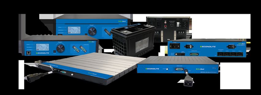
ZincBlue2 Manual
This user manual provides the essential information you need in order to get the most
from your ZincBlue2 Uninterruptible Power Supply & ZincBlue2 Software.

 Copyright © 2021 Econolite All rights reserved.

Table of Contents
List of Figures ZincBlue2 Maintenance
Introduction 34 Routine Maintenance
2 Proprietary Information UPS Operation
2 Copyright 34 Front Panel Overview
2 Trademarks 35 STATUS: NORMAL
Support 36 STATUS: BACKUP
2 Support Contacts 37 STATUS SYSTEM LOG
2 Returns 38 STATUS RELAY STATUS
3 Warranty 39 STATUS SETTINGS
3 About this Manual 40 STATUS SETTINGS SET TIME/DATE
3 Save this Manual 41 STATUS SETTINGS SET TIME/DATE SET TIME FORMAT
3 ZincBlue2 Recycling 42 STATUS SETTINGS SET TIME/DATE SET THE TIME
3 Disclaimer 43 STATUS SETTINGS SET TIME/DATE DAYLIGHT SAVING TIME
4 Safety Symbols 44 STATUS SETTINGS SET TIME/DATE SET DATE FORMAT
4 Uninterruptible Power Supply (UPS) and Battery Safety 45 STATUS SETTINGS SET TIME/DATE SET DATE
5 Warnings and Cautions 46 STATUS SETTINGS EVENTS LIST
6 FRENCH 47 STATUS SETTINGS EVENTS LIST DEFINE EVENT
Sécurité 48 STATUS SETTINGS EVENTS LIST DEFINE EVENT
6 Symboles de sécurité POWER FAILURE
6 Alimentation sans coupure (ASC) et sécurité des batteries 49 STATUS SETTINGS EVENTS LIST DEFINE EVENT SYSTEM FAULT
7 Avertissements et mises en garde 50 STATUS SETTINGS EVENTS LIST DEFINE EVENT TIME
UPS 51 STATUS SETTINGS EVENTS LIST DEFINE EVENT
8 UPS Introduction BATTERY CAPACTIY
8 UPS Overview 52 STATUS SETTINGS EVENTS DEFINE EVENT RELAY
9 Physical Characteristics 53 EVENT SAVE CONFIRMATION
Batteries 54 STATUS SETTINGS POWER FAIL THRESHOLDS
10 ZincBlue2 Battery Panel & Battery Module Introduction 55 STATUS SETTINGS POWER FAIL THRESHOLDS SET LOW
10 ZincBlue2 Battery Panel & Battery Module Overview THRESHOLD
11 Physical Characteristics 56 STATUS SETTINGS POWER FAIL THRESHOLDS SET HIGH
11 ZIncBlue2 XRT Battery Introduction THRESHOLD
11 ZincBlue2 XRT Overview 57 STATUS SETTINGS POWER FAIL THRESHOLDS SET
12 Physical Characteristics ENHANCED SENSITIVITY
13 FRENCH 58 STATUS SETTINGS POWER FAIL THRESHOLDS LINE
Batteries QUALIFY TIME
13 Présentation du panneau et du module de la batterie du l'ZincBlue2 59 STATUS SETTINGS NETWORK
13 Vue d'ensemble du panneau et du module de batterie de l'ZincBlue2 60 STATUS SETTINGS ADDITIONAL SETTINGS SYSTEM RESETS
14 Caractéristiques physiques 60 Description:
Power Interface Module (PIM) 61 STATUS SETTINGS ADDITIONAL SETTINGS TILT ENABLE/DISABLE
15 PIM Introduction 62 STATUS SETTINGS ADDITIONAL SETTINGS ABOUT
15 PIM Overview ZincBlue2 Software
15 Physical Characteristics 63 Introduction
Installation 63 Features
16 Installation Safety 64 Browsers
16 Tools Needed 64 Network Configuration
17 Installing the UPS 64 Windows Configuration
17 Installing ZincBlue2 UPS 1000W/1500W 64 Mac Configuration
18 Installing the Batteries 65 Login
18 Installing ZincBlue2 Battery Panel 500W 66 Home Screen
19 Installing ZincBlue2 Battery Module 500W 67 System Log Tab
19 Installing the ZincBlue2 XRT Battery 3600Wh IMS 69 Relay Status Tab
19 Installing the PIM 70 Events Tab
20 FRENCH 72 Settings Tab
Installation 72 System Settings Page
20 Sécurité de l'installation 73 Network Settings Page
20 Outils requis 74 Firmware Settings Page
21 Installer les batteries 75 Time Settings Page
21 Installer le module de batterie ZincBlue2 500 W 76 User Settings Page
Wiring the System 77 Messaging Settings Page
22 Wiring Safety Theory of Operations
22 ZincBlue2 Cables 78 ZincBlue2 UPS 1000W
23 Wiring the UPS with PIM 79 ZincBlue2 Battery Panel & Battery Module
25 Connecting Battery Panel or Battery Module to UPS and PIM 80 ZincBlue2 PIM
26 ZincBlue2 Wiring Diagram 81 ZincBlue2 XRT Battery 3600Wh
27 FRENCH Troubleshooting
Câblage du système 82 Trouble Analysis
27 Sécurité du câblage 82 Troubleshooting Sequence Chart
27 Câbles ZincBlue2 Limited Warranty
27 Câbles de batteries 3600WH ZincBlue2 Glossary
28 Câblage de l'ASC avec le MIA
29 Communications et I/O
30 Connexion d'un panneau de batterie ou d'un module de
batterie à une ASC et à un MIA
31 Schéma de câblage d'ZincBlue2
32 Wiring the ZincBlue2 XRT
32 Connecting ZincBlue2 XRT to UPS and PIM
32 Installing Additional ZincBlue2 XRT Battery 3600Wh
33 ZincBlue2 XRT Wiring Diagram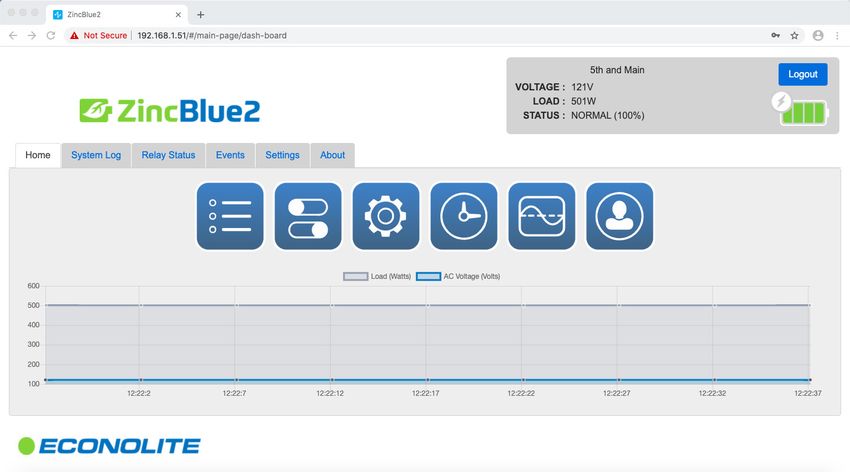
List of Figures
  1        ZincBlue2 Manual                                                   35   UPS Front Panel Overview
  3        ZincBlue2 Recycling                                                36   Status: Home Screen
  4        Danger Symbol                                                      36   Power Failure: Backup Mode
  4        Attention Symbol                                                   37   System Log: No Logs Available
  5        UPS Input & Output Values                                          37   System Log: Logs Available
  6        Symbole de danger                                                  38   Relay Status: No Relays Triggered
  6        Symbole de mise en garde                                           38   Relay Status: Relay Triggered
  7        UPS Input & Output Values                                          39   Settings
  8        ZincBlue2 UPS 1000W/1500W (Front)                                  40   Set Time/Date
  8        ZincBlue2 UPS 1000W (Back)                                         41   Set Time Format
  10       ZincBlue2 Battery Panel 500W                                       42   Set the Time
  10       ZincBlue2 Battery Module 500W                                      43   Daylight Saving Time
  11       ZincBlue2 XRT Battery 3600Wh IMS                                   44   Set Date Format
  11       Z5 13-80 H S                                                       45   Set the Date
  11       1kW Monobloc Nickel-Zinc Battery                                   46   Event List: No Events Defined
  13       ZincBlue2 Battery Panel 500W                                       46   Event List: Events Defined
  13       ZincBlue2 Battery Module 500W                                      47   Define Event
  15       PIM                                                                47   Edit Event
  17       UPS Rack Mount Bracket Installation                                48   Define Event: Power Failure
  17       Installing ZincBlue2 UPS 1000W/1500W                               48   Edit Power Fail Trigger: Power Resume
  17       UPS Rack Mount Installation                                        48   Edit Power Fail Trigger: Power Fail
  18       Spacer Bar                                                         48   Edit Power Fail Trigger: Set Delay Time
  18       Speedy Sleeve                                                      49   Edit System Fault Trig: ON
  18       ZincBlue2 Battery Panel between rack & cabinet wall                49   Edit System Fault Trig: OFF
  18       ZincBlue2 Battery Panel installed                                  50   Edit Time of Day Trigger: Set Start Time
  20       ZincBlue2 XRT Wiring Diagram                                       50   Edit Time of Day Trigger: Set End Time
  21       Installing ZincBlue2 PIM                                           51   Edit Battery Trigger
  21       Battery Module Rack Mount Bracket Installation                     51   Edit Battery Trigger: Set Battery Capacity
  21       Installing ZincBlue2 Battery Module 500W                           52   Edit Relay to Trigger: Set Relay On/Off
  21       ZincBlue2 XRT Battery 3600Wh IMS Rack Mount Bracket                52   Relay Status: On or Off
            Installation                                                      54   Set Power Fail Thresholds
  21       Installing ZincBlue2 XRT Battery 3600Wh IMS                        55   Set Low Threshold
  21       PIM Rack Mount Bracket Installation                                56   Set High Threshold
  21       Battery Module Rack Mount Installation                             57   Set Sensitivity
  21       ZincBlue2 XRT Battery 3600Wh IMS Rack Mount Installation           58   Set Line Qualify Time
  21       PIM Rack Mount Installation                                        59   Network Status
  23       Installation du support de montage en rack des                     60   System Resets: Confirm Configured Data Reset
           modules de batterie                                                60   Additional Settings: System Reset
  23       Installation d'un module de batterie                               60   System Resets: Confirm Firmware Reset
           UPStealth 2 de 500W                                                60   System Resets: Reset Inverter
  23       Installation de montage en rack du module de batterie              61   Additional Settings: Tilt Enable/Disable
  24       Locking AC Power Interconnect Cable                                61   Additional Settings: Tilt On
  24       AC Power Adapter                                                   61   Additional Settings: Tilt Off
  24       AC Power Daisy Chain Cable                                         63   ZincBlue2 Software
  24       Digital and DC Power Interconnect Cable                            65   Login
  24       DC Power Interconnect Cable                                        66   Home Screen
  24       Digital & DC Power Interconnect Cable                              67   System Log Tab
  24       Locking AC Power Interconnect Cable                                68   ZincBlue2 XRT Battery 3600Wh Block Diagram
  24       XRT AC Power Cable                                                 69   List of Event Types
  24       Battery Temperature Sensor Cable                                   69   ZincBlue2 Troubleshooting Flowchart
  28       ZincBlue2 Wiring Diagram                                           70   Relay Status Tab
  29       Verrouillage du câble d'interconnexion d'alimentation en courant   71   Event Tab
           alternatif                                                         72   Event Tab: Create New Event
  29       Adaptateur d'alimentation CA                                       73   Settings Tab: System Settings
  29       Câble d'alimentation en courant alternatif Daisy                   74   Settings Tab: Network Settings
  29       Câble d'interconnexion numérique et d'alimentation en courant      75   Settings Tab: Firmware Settings
           continu                                                            76   Settings Tab: Time Settings
  29       Câble d'interconnexion pour l'alimentation en courant continu      77   Settings Tab: User Settings
  29       Câble d'interconnexion numérique et d'alimentation en courant      78   Settings Tab: Messaging Settings
           continu                                                            78   Settings Tab: SMTP Notification
  29       Verrouillage du câble d'interconnexion d'alimentation en courant   79   ZincBlue2 UPS 1000W Block Diagram
           alternatif                                                         80   ZincBlue2 Battery Panel and Module Block Diagram
  29       Câble d'alimentation XRT CA                                        81   ZincBlue2 PIM Block Diagram
  29       Câble du capteur de température de la batterie                     83   ZincBlue2 Troubleshooting Chart
  33       ZincBlue2 Wiring Diagram

1 | ZincBlue2 User Manual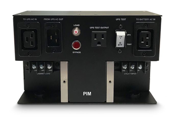
Introduction

Proprietary Information
This document contains information that is confidential and proprietary to Econolite, it may not be reproduced,
distributed, or translated in any other language, in whole or in part, without written approval from Econolite and/or its
associated partners.

Copyright
The user acknowledges that all content included in this document, including the information, data, software,
photographs, graphs, typefaces, graphics, images, illustrations, drawings, designs, icons, written and other material
(collectively, “Content”) and the arrangement and compilation of the Content are intellectual property and
copyrighted works of the manufacturer.

Trademarks
“ZincBlue" is a registered trademark of Econolite. Use of third party trademarks, brand names, trade names and/or prod-
uct names are for informational purpose only and are the trademarks of their respective owners.

Support

Support Contacts
For technical support, please contact an Econolite support representative:

Support Phone: 800.225.6480
Support Email: support@econolite.com
Support Website: wwww.econolite.com/support

Returns
For product returns, please contact an Econolite support representative to obtain a return material authorization (RMA).

Econolite                                                                 Returns Email: repairs@econolite.com
1250 N. Tustin Ave.                                                       Support Phone: 800.225.6480
Anaheim, CA 92807

Save the packaging material in the event a return is needed. Econolite does not warranty product damage from return
shipping unless it is shipped in approved packaging.

                                                                                                   ZincBlue2 User Manual | 2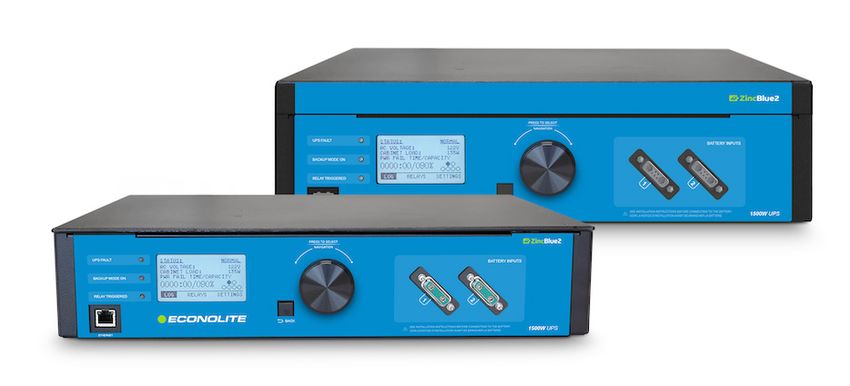
Warranty
  Econolite's ZincBlue2 is covered by Econolite's Limited Warranty. Please refer to the Limited Warranty in the back of the
  manual.

  About this Manual
  This manual contains information to help owners and operators understand how to safely and properly prepare, install
  and operate the Econolite ZincBlue2. Attention to this manual will help avoid risks, reduce repair costs and downtime,
  and increase the reliability of the ZincBlue2.

  Instructions in this manual must be followed to ensure proper installation, operation and maintenance of the system
  in accordance with the Limited Warranty.

  Save this Manual
  This manual provides guidelines for safe and reliable ZincBlue2 operation. Save this manual, it contains important
  installation and operating instructions. If you have any questions about the safe installation, operation, or
  maintenance of the ZincBlue2, contact an Econolite support representative (visit www.econolite.com/support or call
  800.225.6480).

  ZincBlue2 Recycling
  Econolite cares about our environment and has made arrangements for                          Help the Environment.
  users to easily recycle all ZincBlue2 components, including the cases,                       Call ER2, our recycling partner, at
                                                                                               1-844-372-0002 or visit ER2.com to
  electronics, cabling, and batteries at end of life. Each ZincBlue2                           schedule a pick up and learn more!
  component has a recycle label on the back of the enclosure indicating
  how to contact our recycling partner ER2 to properly recycle ZincBlue2
  products.                                                                                    ZincBlue2 Recycling

  Disclaimer
  While efforts have been made to ensure the accuracy and validity of information contained in the document, Econo-
  lite assumes no responsibility and disclaims all liability for any errors and/or omissions that may be contained herein.

  Due to possible changes and/or updates to component design and software applications, this document, completely
  or in part may become obsolete or out-of-date until a subsequent revision is released by Econolite.

  Econolite may make changes to specifications, product descriptions, and documentation at any time, without notice.

3 | ZincBlue2 User Manual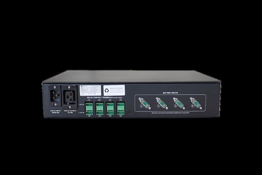
Safety

Safety Symbols
Econolite ZincBlue2 Uninterruptible Power Supplies (ZincBlue2) are carefully designed and tested to ensure that they
are safe and reliable products when used properly. To ensure the safe and proper use of Econolite's ZincBlue2, the
following symbols are used on the product and throughout this manual. Operators, buyers, and technicians must
observe each occurrence of these symbols as they appear throughout the document. Only qualified personnel should
carry out instructions accompanied by these symbols.

					       Danger Symbol                    Attention Symbol
                Danger:                         Attention:
   An electrical danger exists in this   Important information or
    area. Use extreme caution at all   operating instructions. Follow
                 times.                        them exactly.

Uninterruptible Power Supply (UPS) and Battery Safety
       This Uninterruptible Power Supply (UPS) and batteries must be installed in a UL or 3rd party safety approved
       cabinet by trained personnel qualified in the safe use of high-energy power supplies and their batteries.
       Also assumed is knowledge of the local electrical code(s) and their safe application.

       To prevent accidental shorts, shocks or electrocutions, never let water or any form of liquid enter the UPS and
       batteries.

       Do not operate the UPS and batteries with damaged cables and wires. Defective cables and wires must be
       replaced before system installation. Prior to system installation, verify that all cables and wires are properly
       secured and connected. Faulty connections can interrupt operation and cause irreparable damage to this
       product.

       Dismantling or opening the equipment enclosures will void the product warranty and create risk of electrical
       shock. The equipment enclosures should only be opened by a Econolite representative or trained professional.

       Don't leave interconnect cables plugged into batteries when not in use.

       This ZincBlue2 system is design for fail safe operation. With a failure of the ZincBlue2 UPS 1000W/1500W, the
       PIM will automatically bypass in order to provide Utility power to the Cabinet load. The Transfer switch
       internal to the ZincBlue2 UPS 1000W is a normally closed relay contact that defaults to the AC input
       connected to the AC output.

                                                                                                    ZincBlue2 User Manual | 4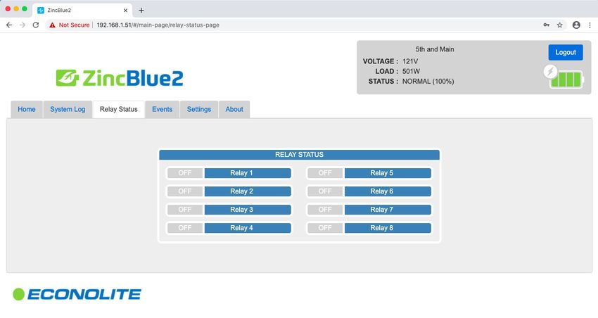
Warnings and Cautions
  UPS
         To avoid fire, shock, or death; turn off power at circuit breaker or fuse and test that power is off before wiring,
         servicing, or removing.
         Read this manual prior to installation and operation. If you have any questions about safe installation, operation or
         maintenance, contact ZincFive’s Support Department.
         Carefully unpack the components. Report any shipping or other damage at once.
         Never let live battery wires touch the UPS, the enclosure, or any other metal objects.
         Use proper lifting techniques when lifting or moving the UPS or its components.
         At high ambient temperature conditions, the UPS’ surface can be very hot to the touch when operating.
         Ensure ventilation to the left and right sides of the UPS enclosure.
         To be installed and/or used in accordance with electrical codes and regulations.
         Before installation, verify the input voltage and current requirements of the load are met by the UPS’ output. Verify
         the line voltage and current meet the UPS input requirements.
                                                                                                                             UPS Input & Output Values
         To avoid electric overload, do not exceed output rating.
          Input Power
                                                                                                                120Vac Nominal
          Input Voltage Range
                                                                                                          85-140Vac User Programable
          Input Current                                                                                             15A max
                                                                                                                 60Hz nominal
          Input Frequency
                                                                                                               +/-10% (54 - 66Hz)
          Output
          Output Voltage                                                                                         120Vac +/-3%
          Output Current                                                                                          8.3A Typical
          Output Power                                                                                          1,000VA Typical
          Output Frequency                                                                                       60Hz +/-0.5Hz
          Output Waveform                                                                                        Pure Sinewave
          UPS Efficiency                                                                                              0.97
          Environmental
          ZincBlue2 UPS 1000W operating temperature range                                                 -37°C to 74°C (-34°F to 165°F)
          Regulatory Compliance
          ZincBlue2 UPS 1000W                                                  UL 1778 and CSA C22.2 No. 107.3 compliant in a maximum ambient environment of 40°C

  Battery Panel / Module

          Battery installation and servicing should be done or supervised by personnel knowledgeable about
          batteries and the required precautions.

          Battery Panel / Module must not be installed in a sealed enclosure, ventilation must be provided.

          Use proper lifting techniques when lifting or moving the batteries.

          Never dispose of batteries in a fire.

          Never open or damage the batteries.

          A battery can present a risk of electrical shock and high short-circuit current. The following precautions should
          be observed when working on batteries:

                           Remove watches, rings, or other metal objects.

                           Use tools with insulated handles.

                           Disconnect the AC input to the Battery prior to connecting or disconnecting battery terminals.

                           Ensure that the Battery is OFF before connecting or disconnecting battery interconnect cables. The
                           Battery Panel / Module indicator LED will be OFF.

                           Never short pins inside battery cable connectors.
5 | ZincBlue2 User Manual
FRENCH

Sécurité

Symboles de sécurité
Les alimentations sans coupure ZincBlue2 de Econolite sont soigneusement conçues et testées pour garantir qu'il
s'agit de produits sûrs et fiables lorsqu'ils sont utilisés correctement. Pour garantir une utilisation sûre et correcte de
l'ZincBlue2 de Econolite, les symboles suivants sont utilisés sur le produit et tout au long de ce manuel. Les opérateurs,
les acheteurs et les techniciens doivent observer chaque occurrence de ces symboles tels qu'ils apparaissent dans le
document. Seul un personnel qualifié doit exécuter les instructions accompagnées de ces symboles.

  Symbole de danger                                                           Symbole de mise en garde
                     Danger :                                                        Attention :
  Un danger électrique existe dans cette zone. Faire                Renseignements importants ou instructions
  preuve d'une extrême prudence à tout moment.                         d'utilisation. Suivre avec exactitude.

Alimentation sans coupure (ASC) et sécurité des batteries
         Cette alimentation sans coupure (ASC) et ses batteries doivent être installées dans une armoire homologuée
         par UL ou une tierce partie par un personnel formé et qualifié dans l'utilisation sûre des alimentations haute
         énergie et de leurs batteries. Il est également supposé connaître le(s) code(s) électrique(s) local(aux) et leur
         application en toute sécurité.

         Pour éviter tout court-circuit, choc ou électrocution accidentels, ne jamais laisser de l'eau ou toute forme de
         liquide pénétrer dans l'ASC et les batteries.

         Ne pas faire fonctionner l'ASC et les batteries avec des câbles et des fils endommagés. Les câbles et fils dé
         fectueux doivent être remplacés avant l'installation du système. Avant l'installation du système, vérifier que
         tous les câbles et fils sont correctement fixés et connectés. Des connexions défectueuses peuvent interrompre
         le fonctionnement et causer des dommages irréparables à ce produit.

         Le démontage ou l'ouverture des boîtiers de l'équipement annulera la garantie du produit et créera un risque
         de choc électrique. Les boîtiers des équipements ne doivent être ouverts que par un représentant de Econolite
         ou un professionnel qualifié.

         Ne pas laisser les câbles d'interconnexion branchés sur des batteries lorsqu'ils ne sont pas utilisés.

         Ce système ZincBlue2 est conçu pour fonctionner en toute sécurité. En cas de panne de l'ASC ZincBlue2
         de 1000W/1500W, le MIA (module d'interface d'alimentation) sera automatiquement contourné afin de
         fournir une alimentation électrique à la charge de l'armoire. Le commutateur de transfert interne à l'ASC
         ZincBlue2 de 1000W/1500W est un contact de relais normalement fermé qui correspond par défaut à l'entrée
         CA Le commutateur de transfert interne à l'ZincBlue2 ASC 1000W/1500W est un contact de relais
         normalement fermé qui est relié par défaut à l'entrée CA connectée à la sortie CA.
                                                                                                      ZincBlue2 User Manual | 6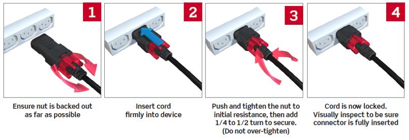
Avertissements et mises en garde
  ASC

          Pour éviter un incendie, un choc ou la mort, couper le courant au niveau du disjoncteur ou du fusible et vérifier que
          l'alimentation est coupée avant de procéder au câblage, à l'entretien ou au démontage.
          Lire ce manuel avant l'installation et l'utilisation. Si vous avez des questions concernant l'installation, le fonctionne-
          ment ou l'entretien en toute sécurité, contacter le service d'assistance de ZincFive.
          Déballer soigneusement les composants. Signaler immédiatement tout dommage lié au transport ou autre.
          Ne jamais laisser des fils de batteries sous tension toucher l'ASC, le boîtier ou tout autre objet métallique.
          Utiliser des techniques de levage appropriées lorsque l'ASC ou ses composants sont soulevés ou déplacés.
          Dans des conditions de température ambiante élevée, la surface de l'ASC peut être très chaude au toucher lors de
          son fonctionnement.
          Veiller à ce que la ventilation soit assurée sur les côtés gauche et droit du boîtier de l'ASC.
          Être installé et/ou utilisé conformément aux codes et réglementations électriques.
          Avant l'installation, vérifiez que la tension d'entrée et les besoins en courant de la charge sont satisfaits par la sortie
          de l'ASC. Vérifier que la tension et le courant de ligne répondent aux exigences d'entrée de l'ASC.
          Pour éviter toute surcharge électrique, ne pas dépasser la puissance nominale.
                                                                                                                                           UPS Input & Output Values

           Input Power
                                                                                                                120Vac Nominal
           Input Voltage Range
                                                                                                          85-140Vac User Programable
           Input Current                                                                                            15A max
                                                                                                                 60Hz nominal
           Input Frequency
                                                                                                               +/-10% (54 - 66Hz)
           Output
           Output Voltage                                                                                        120Vac +/-3%
           Output Current                                                                                         8.3A Typical
           Output Power                                                                                         1,000VA Typical
           Output Frequency                                                                                      60Hz +/-0.5Hz
           Output Waveform                                                                                       Pure Sinewave
           UPS Efficiency                                                                                             0.97
           Environmental
           ZincBlue2 UPS 1000W operating temperature range                                                -37°C to 74°C (-34°F to 165°F)
           Regulatory Compliance
           ZincBlue2 UPS 1000W                                                 UL 1778 and CSA C22.2 No. 107.3 compliant in a maximum ambient environment of 40°C

  Panneau / module de batteries

          L'installation et l'entretien des batteries doivent être effectués ou supervisés par un personnel connaissant les
          batteries et les précautions requises.
          Le panneau / module de batteries ne doit pas être installé dans une enceinte étanche, une ventilation doit
          être prévue.
          Utilisez des techniques de levage appropriées lorsque vous soulevez ou déplacez les batteries.
          Ne jamais jeter de batteries dans un feu.
          Ne jamais ouvrir ou endommager les batteries.
          Une batterie peut présenter un risque de choc électrique et de courant de court-circuit élevé. Les précautions
          suivantes doivent être observées lorsque vous travaillez sur des batteries
                    Retirer toutes montres, bagues ou autres objets métalliques.
                    Utiliser des outils avec des poignées isolées.
                    Débrancher l'entrée CA de la batterie avant de connecter ou de déconnecter les bornes de la batterie.
                    S'assurer que la batterie est éteinte avant de connecter ou de déconnecter les câbles
                    d'interconnexion de la batterie. Le voyant du panneau/module de la batterie sera éteint.
                           Ne jamais court-circuiter les broches à l'intérieur des connecteurs des câbles de la batterie.

7 | ZincBlue2 User Manual
UPS
UPS Introduction
The ZincBlue2 UPS 1000W and ZincBlue2 UPS 1500W (ZincBlue2 UPS 1000W/1500W) are 1000 Watt and 1500 Watt
UPS systems that utilizes an Intelligent Two Stage Operation with an oscilloscope function and is developed to
operate with nickel-zinc batteries. It is designed for installation in all signalized and ITS cabinets and can be rack
mounted in 2U - 19'' EIA racks or shelf mounted.
11 10
1
2
3
4
9 8
5 6 7 8
ZincBlue2 UPS 1000W/1500W (Front) ZincBlue2 UPS 1000W (Back)
ZincBlue2 UPS 1000W/1500W functions using an Intelligent Two Stage operation.
Stage 1: This stage includes Line Conditioner, Waveform Monitoring and Switchover to battery backup functions. The
line conditioner function attenuates surges and spikes on incoming utility power. Oscilloscope functionality
continuously measures the incoming AC waveform and monitors for voltage, frequency and waveform anomalies
outside of user programmed thresholds. When any voltage, waveform or frequency threshold is exceeded, transfer
time to battery backup is a rapid• The UPS input voltage is out of spec
• The UPS inverter is not operational
• The load is too high for the UPS
• The ambient temperature is outside the operational requirement of the UPS
• The battery voltage is too low
• No batteries are attached or available
• The tilt switch is activated while the UPS is in backup mode
3. BACKUP MODE ON (Solid Green)
The solid green LED will be ON any time the UPS is supplying backup power from the batteries.
BACKUP MODE ON (Flashing Green)
The flashing green LED will be ON any time the UPS is supplying backup power and the batteries are below 10% capacity. The
green LED will flash at a frequency of twice per second.
4. RELAY TRIGGERED (Solid Yellow)
The solid yellow LED will be ON when any of the user configurable relays are activated.
5. ETHERNET
If your ZincBlue2 is connected to a network, direct connection to the ethernet port will allow access to the ZincBlue2
Software web application. The Ethernet port can also be used for local firmware updates.
6. BACK
The push button changes the display to the previous menu or screen and serves as a BACK button and SAVE funtion.
7. NAVIGATION DIAL
Rotating navigation dial for control of the LCD screen cursor. Pushing the dial functions as a Select button.
8. BATTERY INPUTS
Six (6) battery inputs for connecting
battery panels/module to the UPS via
the provided Digital and DC Power
Interconnect Cable. UPS is certified
for use with only the following
Econolite batteries.
Note: When using a UPStealth 2 UPS 1500W it is a system requirement that two UPStealth 2 Battery Panels or Battery
Modules be used or a single UPStealth 2 XRT Battery 3600Wh. If not configured with the mentioned batteries, the
UPStealth 2 UPS 1500W will be in "BACKUP UNAVAILABLE" mode until the correct configuration is in place.
9. RELAY CONTACT TERMINALS
8 independent programmable relays with NO (normally open) and NC (normally closed) contacts. Relays can be programmed
for the following: Power Failure, Power Resume, System Faults, Time of Day, Battery capacity %.
10. UPS AC OUTPUT TO PIM
Connection between UPS AC Output to PIM via the provided Locking AC Power Interconnect Cable.
11. UPS AC INPUT FROM PIM
Connection between UPS AC Input from PIM via the provided Locking AC Power Interconnect Cable.
Physical Characteristics
ZincBlue2 UPS 1000W……………3.7”H x 17”W (19” w/ mounting) x 11.6”D Weight 12 lbs.
ZincBlue2 UPS 1500W……………4.6”H x 17”W (19” w/ mounting) x 11.6”D Weight 14 lbs.
9 | ZincBlue2 User ManualBatteries
ZincBlue2 Battery Panel & Battery Module Introduction
The ZincBlue2 Batteries are available in two form factors, the ZincBlue2 Battery Panel and ZincBlue2 Battery
Module. Both are 500W form factors operating with nickel-zinc batteries and an intelligent battery management
system. The batteries can be charged with either the ZincBlue2 UPS 1000W/1500W or the Wall Charging Adapter.
4
5
2
1 1 2
3 3 5
ZincBlue2 Battery Panel 500W ZincBlue2 Battery Module 500W
ZincBlue2 Battery Panel & Battery Module Overview
1. COLD START
Manually cold start the ZincBlue2 using the batteries to enable quick startup of an intersection. With a battery
panel or module connected to a UPS, push and hold for 5 seconds for immediate system cold startup. Hold for 10
seconds to turn off.
2. BATTERY OUTPUT
The connection point between the Battery and UPS via the provided Digital and DC Power Interconnect Cable.
3. AC INPUT
The connection point between the Battery and PIM. Use the provided Locking AC Power Interconnect Cable.
4. HANDLE
Used for lifting the battery panel.
5. STATUS
A multi-color LED indicators that provides battery status
• Green = Backup Mode
• Blue = Charging Mode
• Red = Battery Fault
• White Blinking = Charged, battery at rest
FORCE OFF
Press and hold the Cold Start button for 10 seconds to turn off the Battery Panel/Module.
Hot Swapping when in discharge mode, you should do/see the following:
1. Connect the new battery to the controller via the DC interconnect cable. New battery LED should turn on
(Green), and be recognized by the controller.
2. Disconnect DC and AC cable from depleted battery and remove.
3. Connect the AC cable to the new battery. Disconnecting the depleted batteries before connecting fresh batter-
ies may cause premature system shutoff when in discharge mode.
When the system is in Normal/AC mode, the AC and the DC cables will both need to be connected to the battery
to turn it on and have it be recognized by the controller.
ZincBlue2 User Manual | 10Physical Characteristics
ZincBlue2 Battery Panel 500W.................1.1"H x 19"W x 24.4"D 24.4 lbs.
ZincBlue2 Battery Module 500W..............2.3"H x 17"W (19” w/ mounting) x 12.1"D 21.1lbs.
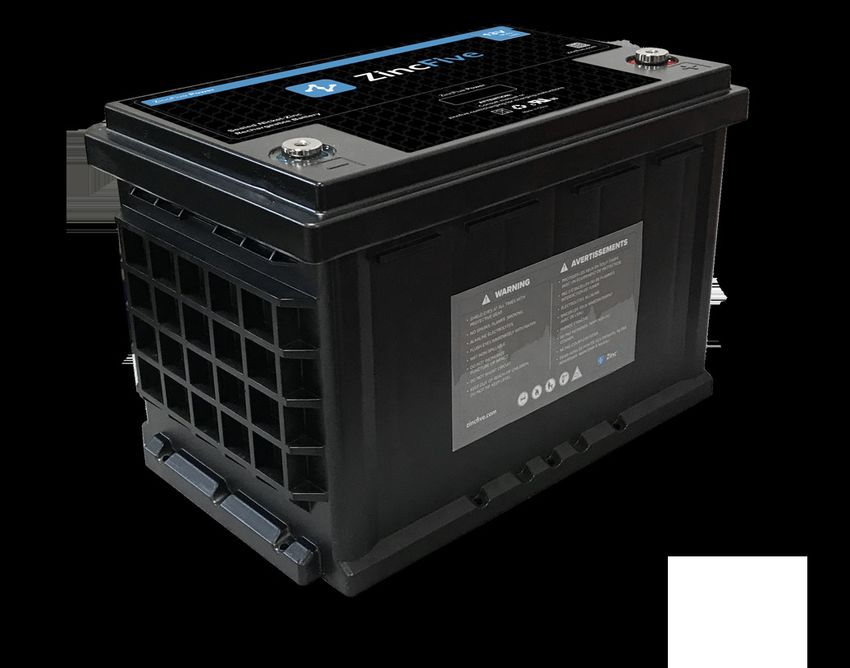
ZIncBlue2 XRT Battery Introduction
The Econolite ZincBlue2 XRT Battery 3600Wh (ZincBlue2 XRT) is available in one form factor and comes with the
ZincBlue2 XRT Battery 3600Wh IMS and four monobloc nickel-zinc batteries.
3 7 9
1 6 8 2 5 4
ZincBlue2 XRT Battery 3600Wh IMS Z5 13-80 H S F
1kW Monobloc Nickel-Zinc Battery
ZincBlue2 XRT comes with a 3600Wh intelligent management system that connects to four 1kW monobloc
nickel-zinc batteries. For full operation, the system must include the ZincBlue2 UPS and PIM.
ZincBlue2 XRT Overview
1. COLD START/FORCE OFF
Manually cold start the ZincBlue2 XRT to enable quick startup of an intersection. With the monobloc nickel-zinc
batteries connected, push and hold for 5-8 seconds for immediate system cold startup. Hold for 10-20 seconds to
turn off.
2. BATTERY OUTPUT
The connection point between the ZincBlue2 XRT and ZincBlue2 UPS 1000W/1500W via the provided Digital and
DC Power Interconnect Cable.
3. AC INPUT
The connection point between the ZincBlue2 XRT and PIM via the provided Locking AC Power Interconnect Cable.
Note: If installing multiple ZincBlue2 XRT Battery 3600Wh units, each additional unit will need to be
independently connected to a 20Amp protected AC circuit via the AC INPUT port on the front of the ZincBlue2
XRT Battery 3600Wh IMS with the XRT AC Power Cable. Additional ZincBlue2 XRT Battery 3600Wh units cannot
be daisy-chain connected to the PIM.
11 | ZincBlue2 User Manual4. BATTERY INPUTS
Four individual connection points between the monobloc nickel-zinc batteries and ZincBlue2 XRT via the
provided DC Power Interconnect Cable.
5. BATTERY STATUS
Four multi-color LED indicators that provide individual monobloc nickel-zinc battery status:
• Green (Solid) - Backup Mode
• Blue (Solid) - Charging Mode
• White (Blinking) - Charged, battery at rest
• Red (Solid) - Battery Missing/Miswired
• Red (Blinking) - Battery Fault. Call your representative for assistance
• Red / Blue (Alternating) - Weak battery detected, charge mode.
• Red / Green (Alternating) - Weak battery detected, discharge mode.
6. MICRO USB PORT
Reserved for manufacturer use.
7. AC POWER
A 20Amp Breaker to turn AC ON/OFF.
8. BATTERY TEMPERATURE
Battery Temperature Sensor is necessary for proper temperature compensated charging of the monobloc
nickel-zinc batteries. Connect the battery temperature sensor cable to the port on the ZincBlue2 XRT and
connect the ringed end to any battery terminal. This cable is required for system operation.
9. BATTERY POWER
A 50Amp Breaker to turn the Battery DC Bus ON/OFF.
Physical Characteristics
ZincBlue2 XRT Battery 3600Wh IMS. . . . . . . . . . . . . . . .. . . . . . . . . . . . . . . . . . . . . . . . 3.4"H x 16.7"W (19” w/ mounting) x 10.2"D 11 lbs.
Z5 13-80 H S (1kW Monobloc Nickel-Zinc Battery). . . .. . . . . . .. . . . . . .. . . 7.4"H x 6.9"W x 10.9"D 33 lbs.
ZincBlue2 User Manual | 12FRENCH
Batteries
Présentation du panneau et du module de la batterie du l'ZincBlue2
Les batteries de l'ZincBlue2 sont disponibles sous deux formes, le panneau de batteries de l'ZincBlue2 et le module de
batteries de l'ZincBlue2. Tous deux sont des facteurs de forme de 500W fonctionnant avec des batteries
nickel-zinc et un système intelligent de gestion de batteries. Les batteries peuvent être chargées avec l'ASC ZincBlue2
de 1000W/1500W ou avec l'adaptateur de charge mural.
4
5
2
1 1 2
3 3 5
ZincBlue2 Battery Panel 500W ZincBlue2 Battery Module 500W
Vue d'ensemble du panneau et du module de batterie de l'ZincBlue2
1. MARRAGE À FROID
Démarrer manuellement à froid l'ZincBlue2 en utilisant les batteries pour permettre le démarrage rapide d'une
intersection. Avec un panneau ou un module de batterie connecté à l'ASC, appuyer et maintenir pendant 5
secondes pour un démarrage à froid immédiat du système. Maintenir pendant 10 secondes pour l'éteindre.
2. SORTIE DE LA BATTERIE
Le point de connexion entre la batterie et l'ASC via le câble d'interconnexion numérique et d'alimentation en
courant continu fourni.
3. ENTRÉE CA
Le point de connexion entre la batterie et le MIA Utiliser le câble d'interconnexion d'alimentation CA à verrouillage
fourni.
4. POIGNÉE
Utilisée pour le levage du panneau de batterie.
5. ÉTAT
Un indicateur DEL multicolore qui indique l'état de la batterie
• Vert= Mode de sauvegarde
• Bleu = Mode de chargement
• Rouge = Défaillance de la batterie
• Blanc clignotant = Chargé, batterie au repos
FORCE OFF
Appuyer sur le bouton de démarrage à froid et le maintenir enfoncé pendant 10 secondes pour éteindre le panneau/
module de la batterie.
13 | ZincBlue2 User ManualPour l'échange à chaud en mode de décharge, vous devez faire/voir ce qui suit:
1. Connecter la nouvelle batterie au contrôleur via le câble d'interconnexion CC. Le voyant de la nouvelle batterie
devrait s'allumer (vert) et être reconnu par le contrôleur.
2. Débrancher les câbles CC et CA de la batterie épuisée et les retirer.
3. Connecter le câble CA à la nouvelle batterie. Le débranchement des piles épuisées avant de brancher des piles
neuves peut entraîner l'arrêt prématuré du système lorsqu'il est en mode de décharge.
Lorsque le système est en mode Normal/CA, les câbles CA et CC devront tous deux être connectés à la batterie
pour la mettre en marche et la faire reconnaître par le contrôleur.
Caractéristiques physiques
ZincBlue2 Battery Panel 500W.................1,1po H x 19 po L x 24,4 po P 24,4 lb.
ZincBlue2 Battery Module 500W..............2,3 po H x 17 po L (19 po avec montage) x 12,1 po P 21,1lb.
ZincBlue2 User Manual | 14Power Interface Module (PIM)
PIM Introduction
1 2 6 3 7 9
The Power Interface Module (PIM) provides an easy-to-connect interface
for incoming utility AC connecting to the UPS and the load.
The PIM provides an auto bypass function that enables the
technician to remove and service the UPS without shutting down
utility power. If, for any reason, the ouput of the ZincBlue2 UPS 1000W/1500W
is not available, then the PIM will automatically connect the load to the
utility line voltage.
4 5
8
PIM
PIM Overview
1. TO UPS AC IN
AC Input from PIM to UPS via the provided Locking AC Power Interconnect Cable.
2. FROM UPS AC OUT
AC Output from UPS to PIM via the provided Locking AC Power Interconnect Cable.
3. UPS TEST OUTPUT
Test output for the UPS. This output is always connected to the UPS output, regardless of Bypass Switch position.
4. CABINET LOAD
Connection points of the cabinet load to the PIM.
5. UTILITY INPUT
Connection points of AC power from the utility line to the PIM.
6. LOAD
20A breaker protection for the load.
7. UPS TEST
15A breaker/switch on incoming utility AC power.
• In the ON position the AC from utility input is connected to the ZincBlue2 UPS 1000W/1500W providing power. The ZincBlue2 UPS
1000W/1500W is passing utility Input power through to the CABINET LOAD as well as the UPS TEST OUPUT on the PIM. No Battery
backup is used (assuming AC Utility power is present).
• In the OFF position the AC from utility input is removed from the ZincBlue2 UPS 1000W/1500W and backup mode will be active.
Note: The UPS TEST switch is NOT used to check runtime as it does not disconnect AC POWER from the Battery Panel/Module.
8. BYPASS LIGHT
Will be lit when utility is directly connected to cabinet load.
9. TO BATTERY AC IN
ZincBlue2 Battery Panel/Module: The connection between the PIM and Battery AC Input on the ZincBlue2 Battery Panel
or Module via the provided Locking AC Power Interconnect Cable.
ZincBlue2 XRT Battery 3600Wh: The connection between the PIM and Battery AC INPUT on the ZincBlue2 XRT Battery
3600Wh IMS via the provided Locking AC Power Interconnect Cable.
Physical Characteristics
PIM. . ...............6”H x 10”W x 4”D 3.7 lbs.
15 | ZincBlue2 User ManualInstallation
Installation Safety
A battery can weigh up to 33 lbs. To avoid injury, use proper lifting techniques when unboxing and
installing.
UPS or battery(s) installation on a cabinet shelf or rack mount above your head is not recommended without
the use of properly staged ladders and assistance in lifting and placing the equipment.
Save the packaging material in the event a return is needed. Econolite does not warrant against product
damage from return shipping unless it is shipped in the original packaging.
The ZincBlue2 system should be installed in a restricted access environment and only installed and serviced
by authorized personnel.
Tools Needed
• Slotted screwdriver - (1/8” and 3/16”) 1/8” used for relay contact terminals. 3/16” used for utility and load
connections to PIM.
• Phillips screwdriver - (#2) used for mounting the product.
• Flat head screwdriver - Used for connecting the PIM terminals.
• Wire stripper - Used for proper stripping of wires.
• Crimp tool - Used for terminating ring lugs (not included) Termination to utility input and cabinet load are #8
screws.
• Voltage meter - Used to check for voltage and to ensure proper connections.
• Socket wrench (10mm) - Used to attach the DC Power Interconnect Cable to the monobloc nickel-zinc batteries.
ZincBlue2 User Manual | 16Installing the UPS
The ZincBlue2 UPS 1000W/1500W is designed to be installed inside primary traffic cabinets and is compatible with 170/2070 33X
series and NEMA traffic cabinets.
The ZincBlue2 UPS 1000W/1500W has a TILT SWITCH function which comes disabled and is a feature that can be enabled in the
field via the UPS or ZincBlue2 Software web application. The ZincBlue2 UPS 1000W/1500W must be mounted horizontally for
proper TILT SWITCH functionality. If the ZincBlue2 UPS 1000W/1500W exceeds 15 degrees from level, the devices TILT SWITCH
will become active and will disable the battery bus. The ZincBlue2 UPS 1000W/1500W status screen will read TILT ERROR and
the red UPS FAULT status light will be on. Disconnect the ZincBlue2 UPS 1000W/1500W from AC Power and adjust the rack or
shelf mounting so that the device does not tilt in excess of 15 degrees from level. Then connect AC Power back to the ZincBlue2
UPS 1000W/1500W. The status screen will read NORMAL and have no status lights on. The About page on your ZincBlue2 UPS
1000W/1500W & ZincBlue2 Software will indicate "TILT SWITCH AVAILABLE" when the function is enabled.
Installing ZincBlue2 UPS 1000W/1500W
Installation of the ZincBlue2 UPS 1000W/1500W can be done either by shelf or rack mounting. For shelf installation,
no other hardware is needed. For rack mounting installations, use the provided brackets (2) and screws (8) as shown in
the figures below.
UPS Rack Mount Bracket Installation UPS Rack Mount Installation
(4QTY) Screw 10-32 x 5/16" Phil, FH 18-8 Black Oxide SS (4QTY) Screw 10-32 x 3/8" Square Cone Sems
1000W 1000W
1500W 1500W
Installing ZincBlue2 UPS 1000W/1500W
17 | ZincBlue2 User ManualInstalling the Batteries
The ZincBlue2 Battery Panel 500W and ZincBlue2 Battery Module 500W are designed to be installed inside primary
traffic cabinets. The ZincBlue2 Battery Panel 500W is compatible with 170/2070 33X series traffic cabinets.
ZincBlue2 Battery Module is compatible with 170/2070 33X series and NEMA traffic cabinets.
Installing ZincBlue2 Battery Panel 500W
The ZincBlue2 Battery Panel 500W is not designed to be rack or shelf mounted. The flex design allows it to bend into
the unused space between the rack and cabinet wall of 33X series cabinets as shown in the below figures. The space
bar and speedy sleeve will assist with installation, use the provided figures and steps to install the ZincBlue2 Battery
Panel.
Step 1: Spacer Bar
Insert the spacer bar between the rack and cabinet wall at the bottom of the cabinet.
This will support the bottom of the battery panel when installed.
Spacer Bar
Step 2: Speedy Sleeve
Insert the speedy sleeve between the rack and cabinet wall.
Insert the ZincBlue2 Battery Panel between the cabinet wall and speedy sleeve which is
up against the rack. When installing the ZincBlue2 Battery Panel, start inserting
with the end opposite of the handle going into the cabinet first.
Speedy Sleeve
Front view of cabinet
Top view of cabinet
ZincBlue2 Battery Panel between
rack & cabinet wall
ZincBlue2 Battery Panel
installed
ZincBlue2 User Manual | 18Installing ZincBlue2 Battery Module 500W
The ZincBlue2 Battery Module is installed by shelf mounting or rack mounting. For shelf installation, no other hard-
ware is needed. For rack installation use the provided brackets (2) and screws (12) as shown in the figure below.
Battery Module Rack Mount Bracket Installation Battery Module Rack Mount Installation
(8QTY) Screw 10-32 x 5/16" Phil, FH 18-8 Black Oxide SS (4QTY) Screw 10-32 x 3/8" Square Cone Sems
Installing ZincBlue2 Battery Module 500W
Installing the ZincBlue2 XRT Battery 3600Wh IMS
The ZincBlue2 XRT Battery 3600Wh is installed by shelf mounting or rack mounting. For shelf installation, no other
hardware is needed. For rack installation use the provided brackets (2) and screws (8) as shown in the figure below.
ZincBlue2 XRT Battery 3600Wh IMS Rack Mount ZincBlue2 XRT Battery 3600Wh IMS Rack Mount
Bracket Installation Installation
(4QTY) Screw 10-32 x 5/16" Phil, FH 18-8 Black Oxide SS (4QTY) Screw 10-32 x 5/16" Phil, FH 18-8 Black Oxide SS
Installing ZincBlue2 XRT Battery 3600Wh IMS
Installing the PIM
The PIM can be either rack mounted (19” EIA standard) or placed on a shelf. For shelf installations, no other hardware
is needed. For rack installation use the provided bracket (1) and screws (4) as shown in the figure below.
PIM Rack Mount Bracket Installation PIM Rack Mount Installation
(2QTY) Screw 10-32 x 5/16" Phil, FH 18-8 Black Oxide SS (2QTY) Screw 10-32 x 3/8" Square Cone Sems
Installing ZincBlue2 PIM
19 | ZincBlue2 User ManualFRENCH
Installation
Sécurité de l'installation
Une batterie peut peser jusqu'à 33 livres. Pour éviter les blessures, utiliser des techniques de levage appropriées lors du
déballage et de l'installation.
Il n'est pas recommandé d'installer une ASC ou une ou plusieurs batteries sur une étagère d'armoire ou un support de
montage au-dessus de votre tête sans utiliser des échelles correctement mises en place et sans vous aider à soulever et à
placer l'équipement.
Conserver le matériel d'emballage au cas où un retour serait nécessaire. Econolite n'offre aucune garantie contre les
dommages causés par le retour du produit, sauf s'il est expédié dans son emballage d'origine.
Le système ZincBlue2 doit être installé dans un environnement à accès restreint et ne doit être installé et entretenu que
par du personnel autorisé.
Outils requis
• Tournevis à fente - (1/8 po et 3/16 po) 1/8 po utilisé pour les bornes de contact de relais. 3/16 po utilisé pour les
connexions des services publics et des charges au MIA.
• Tournevis Phillips - (#2) Utilisé pour le montage du produit.
• Tournevis à tête plate - Utilisé pour connecter les terminaux du MIA.
• Pince à dénuder - Utilisée pour le dénudage correct des fils.
• Outil de sertissage - Utilisé pour terminer les cosses annulaires (non incluses) Les terminaisons vers l'entrée du
service public et la charge de l'armoire sont des vis n°8.
• Compteur de tension - Utilisé pour vérifier la tension et pour assurer des connexions correctes.
• Clé à douille (10 mm) - Utilisée pour fixer le câble d'interconnexion de l'alimentation en courant continu aux
batteries monobloc nickel-zinc.
ZincBlue2 User Manual | 20Installer les batteries
Le panneau de batterie ZincBlue2 500W et le module de batterie ZincBlue2 500W sont conçus pour être installés dans des
armoires de circulation primaires. Le panneau de batterie UPStealth 2 500W est compatible avec les armoires de circulation de la
série 170/2070 33X.
Installer le module de batterie ZincBlue2 500 W
Le module de batterie ZincBlue2 est installé par montage en étagère ou en rack. Pour une installation d'étagère, aucun autre
matériel n'est nécessaire. Pour l'installation en rack, utiliser les supports (2) et les vis (12) fournis, comme indiqué dans la figure
ci-dessous.
Installation du support de montage en rack des Installation de montage en rack du module de
modules de batterie batterie
(8QTY) Vis 10-32 x 5/16 po Phil, FH 18-8 Black Oxide SS (4QTÉ) Vis 10-32 x 3/8 po cône carré Sems
Installation d'un module de batterie
ZincBlue2 de 500W
21 | ZincBlue2 User ManualWiring the System
Wiring Safety
Make sure the incoming utility line power is disconnected before making any wiring connections to the PIM.
Throughout installation, proper cable management is necessary for a clean install.
ZincBlue2 Cables
Locking AC Power Interconnect Cable
QTY: 3 | Length: 6ft
Locking cable used for all AC Power interconnects from UPS and PIM, and between PIM and Battery.
AC Power Adapter
QTY: 1 | Length: 1ft
Adapter for Locking AC Power Interconnect Cable to allow wall outlet charging of Battery Panel and Module.
AC Power Daisy Chain Cable
QTY: 1 | Length: 48" to 6"/10" split
Cable used to daisy chain AC Power between batteries.
Digital and DC Power Interconnect Cable
QTY: 1 | Length: 6ft
Cable used to interconnect Battery Output and Battery Input.
ZincBlue2 XRT Battery 3600Wh Cables
DC Power Interconnect Cable
QTY: 4 | Length: 8ft
DC Power Interconnect Cable for connecting ZincBlue2 XRT to the monobloc nickel-zinc batteries.
Digital & DC Power Interconnect Cable
QTY: 1 | Length: 6ft
Cable used to interconnect Battery Output on the ZincBlue2 XRT Battery 3600Wh IMS and Battery
Input on the ZincBlue2 UPS 1000W/1500W.
Locking AC Power Interconnect Cable
QTY: 1 | Length: 6ft
Locking cable used for the connection between the PIM and Battery AC INPUT on the ZincBlue2 XRT
Battery 3600Wh IMS.
XRT AC Power Cable
QTY: 1 | Length: 6ft
Cable used to charge ZincBlue2 XRT via wall outlet (20Amp). Allows charging without PIM and
ZincBlue2 UPS 1000W/1500W. Also required when more than one ZincBlue2 XRT is being used.
Battery Temperature Sensor Cable
QTY: 1 | Length: 6ft
Battery Temperature Sensor for measuring temperature of the monobloc nickel-zinc batteries.
ZincBlue2 User Manual | 22Wiring the UPS with PIM
To electrically connnect the UPS and PIM unit, follow these steps with the utility power supply shut off at the time of
installation:
1. The PIM incorporates ½” conduit connection points to facilitate CABINET LOAD and UTILITY INPUT conduit
connections.
For non-conduit wiring, use the provided knockout bushing to protect the wires.
2. Connect the load to the PIM “CABINET LOAD” with 10 to 12 AWG wires and #8 size ring terminals properly attached
to the wires. The correct torque for the terminals is 16 in. lbs.
• Ensure that ONLY the items requiring UPS support are connected to the CABINET LOAD.
• Ensure the CABINET LOAD, UTILITY INPUT, line and neutral are completely isolated from each other.
• Ensure that the maximum peak load does not exceed the rating of the ZincBlue2 UPS 1000W/1500W.
To prevent accidental shocks to personnel or damage to equipment, verify that the line, neutral, and ground
wires to and from the PIM are going to the correct locations.
"CAUTION" To reduce the risk of fire, connect the UTILITY INPUT only to a circuit provided with 30 A maximum
branch circuit overcurrent protection in accordance with the National Electrical Code, ANSI/NFPA 70 and the
Canadian Electrical Code, Part I, C22.1
Connect the utility line power to the PIM “UTILITY INPUT” with 10 to 12 AWG wires and #8 size ring terminals
properly attached to the wires. The correct torque for the terminals is 16 in. lbs.
Note: A Listed Type 1 or Type 2 Surge Protective Device having a VPR rating maximum 1500 Vpk transient voltage shall be
provided external to the equipment at the AC input. Required to maintain UPS1000 system compliance to UL 1778 and
CSA 107.3.
3. With only the UTILITY INPUT and CABINET LOAD connected.
• Verify proper Line Neutral and Ground connections at the PIM, UTILITY INPUT and CABINET LOAD.
• Close the 30 Amp branch circuit protection device supplying the PIM and measure for the correct voltage
and polarization at the PIM
• Check for 120VAC and correct polarization at the Female EC320 connector for the; TO BATTERY AC IN.
• Check to ensure that NO voltage is present at the FROM UPS AC OUT Male IEC320 connector or the UPS
TEST OUTPUT NEMA 5-15R connector.
• The PIM BYPASS indicator light on the PIM should be illuminated.
4. Connect the UPS AC OUTPUT TO PIM to the FROM UPS AC OUT via the provided Locking AC Power Interconnect
Cables. Connect the TO UPS AC IN to the UPS AC INPUT FROM PIM via the provided Locking AC Power
Interconnect Cables.
• With UPS connected, the PIM will automatically switch out of bypass
When UPS is powered on, the following LEDS will be active on the UPS:
No LEDs are On: UPS powered On with Utility AC and charged batteries attached.
Red LED is On: UPS powered On with Utility AC and no batteries attached.
Green LED is On: UPS powered On with Cold Start from battery(s).
Red LED (Flashing): Utility AC is applied with a cabinet miswire of swapped Hot and Neutral.
23 | ZincBlue2 User ManualCommunications and I/O
1. Connect to the ethernet port of the UPS (If being used. Ethernet cable is not provided by Econolite).
2. Connect to the desired RELAY CONTACT TERMINAL(S) on the UPS (If being used. Wiring is not provided by
Econolite). The relay connection are CLASS 2.
8 7 6 5 4 3 2 1
H H
G G
Relay Contact Terminals Contact Layout
F F
E E
D D
Common (C) Normally Normally
Open (NO) Closed (NC)
C C
Notes:
Dry contacts are classified as Class 2 Relays.
All contacts are user configurable and can be programmed for one or
multiple conditions – see User Manual.
B B
A A
8 7 6 5 4 3 2 1
ZincBlue2 User Manual | 24Connecting Battery Panel or Battery Module to UPS and PIM
ONLY ZincFive batteries may be used with the UPS. Please refer to the UPS Overview for certified batteries.
To connect the battery to the UPS, follow these steps:
1. Connect the UPStealth 2 Battery Panel or Battery Module BATTERY OUTPUT to the BATTERY INPUT of the
UPStealth 2 UPS 1000W/1500W via the provided Digital and DC Power Interconnect Cable.
Note: If the Cold Start button is pressed upon connecting the Battery to the UPS, do not connect or disconnect
the Battery to or from the UPS until the green LED is off and Cold Start has expired. Press the Cold Start button
for 10 seconds to turn off the system.
A1 - GND Digital and DC Power Interconnect Cable
~ 48Vdc
A2 - Battery +
Pins:
1. Can Bus (H)
2. Isolated CAN Bus GND
3. Can Bus (L)
4. 5V
5. Power Fail
2. Connect the UPStealth 2 Battery Panel or Battery Module AC INPUT to the TO BATTERY AC IN on the PIM using the
supplied Locking AC Power Interconnect Cable and AC Power Daisy Chain Cable as needed. When the battery unit is
connected to AC the battery unit LED should:
• White Blinking = Battery at rest
• Blue = Charging Mode
ONLY use the ZincFive provided interconnect cable
Note: When using a UPStealth 2 UPS 1500W it is a system requirement that two UPStealth 2 Battery Panels or
Battery Modules be used or a single UPStealth 2 XRT Battery 3600Wh. If not configured with the mentioned
batteries, the UPStealth 2 UPS 1500W will be in "BACKUP UNAVAILABLE" mode until the correct configuration is in
place.
Overtightening of these red twist locks may/can result in the cable being backed out of the connector.
Please pay specific attention to the installation instructions in the UPStealth 2 UPS User manual.
25 | ZincBlue2 User Manual8 7 6 5 4 3 2 1
REV. DESCRIPTION DATE BY
B00 BETA RELEASE 12/26/18 DW
ZincBlue2 UPS 1000W ZincBlue2 UPS 1000W
H Front View Rear View H
ZincBlue2 Wiring Diagram
G G
ZincBlue2 Wiring Diagram
ZincBlue2 Battery Module 500W
Class 2 Relay
connections
F ZincBlue2 Battery Panel 500W F
ZincBlue2 Battery Panel 500W
AC TO UPS
E E
AC FROM UPS
ZincBlue2 Battery Panel 500W
SERVICE PANEL
(30Amp Branch Circuit Protection) ZincBlue2 PIM
ZincBlue2 Battery Panel 500W
D D
NEUTRAL EQ GND
BUSS
CABINET UTILITY
C C
ZincBlue2 Battery Module 500W
G
N AC POWER
TO CABINET
EQUIP MENT AC+ GND AC- N
AC+ INPUT
G
B L
B
L
N
G
AC+ G ND AC-
UTILITY
POW ER
A INPUT A
8 7 6 5 4 3 2 1
ZincBlue2 User Manual | 26FRENCH
Câblage du système
Sécurité du câblage
S'assurer que l'alimentation électrique de la ligne d'arrivée est déconnectée avant d'effectuer tout
branchement sur le MIA.
Tout au long de l'installation, une bonne gestion des câbles est nécessaire pour une installation propre.
Câbles ZincBlue2
Verrouillage du câble d'interconnexion d'alimentation en courant alternatif
QTÉ : 3 | Longueur : 6 pi.
Câble de verrouillage utilisé pour toutes les interconnexions d'alimentation en courant alternatif entre l'ASC
et le MIA, et entre le MIA et la batterie.
Adaptateur d'alimentation CA
QTÉ : 1 Longueur : 1 pi.
Adaptateur pour le verrouillage du câble d'interconnexion d'alimentation en courant alternatif afin de
permettre le chargement du panneau et du module de batterie à partir d'une prise murale.
Câble d'alimentation en courant alternatif Daisy
QTÉ : 1 | Longueur : Séparation 48 po à 6 po / 10 po
Câble utilisé pour enchaîner le courant alternatif entre les batteries.
Câble d'interconnexion numérique et d'alimentation en courant continu
QTÉ : 1 | Longueur : 6 pi.
Câble utilisé pour interconnecter la sortie de la batterie et l'entrée de la batterie.
Câbles de batteries 3600WH ZincBlue2
Câble d'interconnexion pour l'alimentation en courant continu
QTÉ : 4 | Longueur : 8 pi.
Câble d'interconnexion d'alimentation en courant continu pour connecter l'ZincBlue2 XRT aux batteries
monobloc nickel-zinc.
Câble d'interconnexion numérique et d'alimentation en courant continu
QTÉ : 1 | Longueur : 6 pi.
Câble utilisé pour interconnecter la sortie de la batterie de l'ZincBlue2 XRT Battery 3600Wh IMS et
l'entrée de la batterie de l'ZincBlue2 UPS 1000W/1500W.
Verrouillage du câble d'interconnexion d'alimentation en courant alternatif
QTÉ :1 | Longueur : 6 pi.
Câble de verrouillage utilisé pour la connexion entre le MIA et L'ENTRÉE CA de la batterie sur l'ZincBlue2 XRT
Batterie 3600Wh IMS.
Câble d'alimentation XRT CA
QTÉ : 1 | Longueur : 6 pi.
Câble utilisé pour charger ZincBlue2 XRT via une prise murale (20Amp). Permet de charger sans MIA et
ZincBlue2 UPS 1000W/1500W. Également requis lorsque plus d'un ZincBlue2 XRT est utilisé.
Câble du capteur de température de la batterie
QTÉ : 1 | Longueur : 6 pi.
Capteur de température de batterie pour mesurer la température des batteries monobloc nickel-zinc.
27 | ZincBlue2 User ManualYou can also read