ZW - Instruction manual Manuel d'instruction - PERFECT-van-Wamel
←
→
Page content transcription
If your browser does not render page correctly, please read the page content below
ZW

          Version
           V.03

                    Instruction manual
                              -
                    Manuel d'instruction

                 Van Wamel B.V.          +31 (0) 487 59 29 44      Uw PERFECT dealer
                 Energieweg 1, 6658 AE   www.perfectvanwamel.com
                 Beneden Leeuwen         perfect@vanwamel.nl
                 The Netherlands         parts@vanwamel.nl
Van Wamel B.V.
Multi Mower
                                               Multi Broyeur
                                                 Type ZW
                                               Version V.03

                                                01-01 2019

E   Instruction manual, page 3 and following
    Parts list, page 100 and following

F   Manuel d'instruction, page 50 et suivant
    Pièces de rechange, page 100 et suivant

                                                        © Copyright 01-01 2019 Van Wamel B.V.
2
INSTRUCTION MANUAL

                                                       Multi Mower

                                                         Model ZW

                                                       Version V.03

Before you take the mower in service the first time, you must read this instruction manual attentive and take also care of
the mentioned precautionary measures.

          In this manual all items concerning your safety are marked with this symbol. Pass all these user and precaution
             instructions also to other users.

When ordering spare parts, please indicate model name and serial number, part number and description as given in this parts list.
We advise you to write the model name and serial number (see number plate on machine) on the Declaration of Conformity
(chapter 1.14 page 16)

We wish you every success with your ”PERFECT” Multi Mower!

                                                                                    © Copyright 01-01 2019 Van Wamel B.V.

                                                               3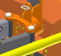
4
◼ Contents
1. INSTRUCTION MANUAL ........................................................................................................................................................ 6
1.1 General information ......................................................................................................................................................... 6
    1.1.1 Machine identification ............................................................................................................................................. 6
    1.1.2 The permitted application ........................................................................................................................................ 6
1.2 Precautions ....................................................................................................................................................................... 7
    1.2.1 General Precautions ................................................................................................................................................. 7
    1.2.2 P.T.O. driven machine ............................................................................................................................................. 7
    1.2.3 Service ..................................................................................................................................................................... 8
1.3 Technical information ...................................................................................................................................................... 8
1.4 Putting in servic................................................................................................................................................................ 8
    1.4.1 Fitting to the tractor ................................................................................................................................................. 8
    1.4.2 Obstacle Safety Device ............................................................................................................................................ 9
    1.4.3 Cutting height .......................................................................................................................................................... 9
    1.4.4 P.T.O. shaft .............................................................................................................................................................. 9
    1.4.5 Gearbox ................................................................................................................................................................. 10
    1.4.6 Transport ................................................................................................................................................................ 10
1.5 Precautions ..................................................................................................................................................................... 10
1.6 Driving speed ................................................................................................................................................................. 10
1.7 Gearbox .......................................................................................................................................................................... 10
1.8 V-Belts............................................................................................................................................................................ 11
1.9 Flails ............................................................................................................................................................................... 11
    1.9.1 General................................................................................................................................................................... 11
    1.9.2 In service................................................................................................................................................................ 12
    1.9.3 P.T.O. / flail rotor speed ........................................................................................................................................ 12
    1.9.4 Replacement of flails ............................................................................................................................................. 12
1.10 Service ............................................................................................................................................................................ 12
    1.10.1 P.T.O. shaft ............................................................................................................................................................. 12
    1.10.2 Bearing houses / flail rotor ..................................................................................................................................... 12
    1.10.3 Frame pivot point ................................................................................................................................................... 13
    1.10.4 Articulating arm ..................................................................................................................................................... 13
    1.10.5 Rear roller .............................................................................................................................................................. 13
1.11 Important advises ........................................................................................................................................................... 13
    1.11.1 Winter services ...................................................................................................................................................... 13
    1.11.2 Repair..................................................................................................................................................................... 13
    1.11.3 Torque Moments bolt connections......................................................................................................................... 14
    1.11.4 Caution................................................................................................................................................................... 14
1.12 Fault table ....................................................................................................................................................................... 14
1.13 Safety stickers ................................................................................................................................................................ 16
1.14 Declaration of Conformity ............................................................................................................................................. 16

                                                                                            5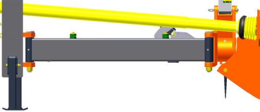
1. Instruction manual
SAFETY INSTRUCTIONS
In this manual all subjects concerning the users and/or bystander safety are marked with the attention symbol as printed
here above. Any persons using this equipment should be notified of these instructions and precautions.
1.1 General information
1.1.1 Machine identification
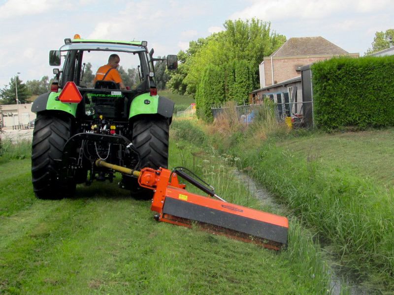
The model name of Perfect equipment consists of two letters and a number. The letters "ZW" indicates this flail chopper is
designed for cutting grass, rushes, reed stems, brush etc. up to 30 mm (1¼”) diameter
- This 3-point model flail mower is standard provided with a hydraulically offset device. The machine can work either
approximately straight behind the tractor or in different offset positions.
- The "ZW" flail mower is equipped with a full cutting-width rear roller.
- Optionally, these machines can be equipped with various options to be expanded,
Several type of flails.
“Pro-Fix” flail construction
Front option.
1.1.2 The permitted application
• This chopper may only be used for the kind of work for which it has been developed;
- cutting grass, rushes, reed stems, brush etc. up to 30 mm (1¼”) diameter
- maintenance of road sides, parking lots, golf-courses, airstrips etc.
- no to work on uneven and/or rocky territories
• The manufacturer is safeguarded against all damage caused by working- / cutting-conditions not mentioned/permitted by
the manufacturer. All damages/costs caused by this kind of usage are for the account of the user of the machine.
• To the right way to use the machine belongs also:
- to take care of the permitted applications of the machine
- to respect the safety- and precaution-instructions, see chapter 1.2
- to respect the maintenance- and service-instructions, see chapter 1.2
- to replace parts always by original Perfect spare parts or by spare parts which apply to the Perfect specifications.
• This machine may only be used and/or maintained, serviced by workers/mechanics who have read this instruction
manual attentive, who have experience to work with / to service this kind of machinery and who have been pointed out
the danger of this kind of machinery.
• The user should take care of the following rules and prescriptions:
- general safety measures
- precaution
- general traffic rules.
• Check the precaution decals on the machine and handle in accordance herewith. Replace lost or damaged decals
straightaway by new-ones.
• The manufacturer is safeguarded against all kind of damages/costs and/or injury caused by alteration(s) of the machine
done without a written permission of the manufacturer. All consequences of this kind of alternations are for the account
of the owner/user.
• It is strongly recommended not to work on rough terrain with this machine. Stones and/or other kind of massive object
can damage the machine. Also this can create dangerous situations. Be careful no stones or other massive objects
come(s) under this machine.
In spite of all precautions is it forbidden that except of the tractor driver anybody else (also animals) stays
nearby (less than 100 m) the machine whilst it is working / running.
6
MAIN PRECAUTION

          Every time before you take the machine in service you must check the machine and the tractor on all
           safety precautions.

1.2 Precautions
1.2.1    General Precautions
   1.    The warning decals on the machine give you important assignments how to use the machine (see also chapter 1.10).
   2.    Check presence of all decals, and replace them straightaway if necessary.
   3.    During night road-transport and also when weather conditions make this necessary the tractor and machine must be
         provided with correct illumination.
   4.    Take care of all precautions written in this manual and prescribe by the law.
   5.    Before taking the machine in service you must make yourself familiar with all functions and parts of the machine.
   6.    Because of spinning parts (P.T.O. shaft, pulleys and V-belts) it is recommended strongly that the tractor driver wears
         tight-fitting cloths.
   7.    To limit fire-risk it is recommended strongly to clean the machine at regular times, also underneath the protection
         covers.
   8.    The machine must be coupled to the tractor as written in this manual.
   9.    When the machine is coupled to the tractor, the tractor must be secured against rolling by the hand-brake. During
         coupling it is forbidden to stay in between tractor and machine.
   10.   During road transportation the machine must always be coupled in central position.
   11.   Tractor front-counter-weights must be placed at the prescribed places.
   12.   Pay attention to the maximum allowed axe-load, especial by front mounted machines.
   13.   It is forbidden to transport people and/or animals on the machine during work and/or road-transport.
   14.   Before you put the machine in service you must check if nobody, also children and animals, stays nearby the
         machine. Be aware you have an unobstructed view.
   15.   During road-transport and work it is forbidden to the tractor driver to leave the cabin.
   16.   Adapt the speed to the circumstances. Be careful when working at hill sides and at sharp turns.
   17.   The drive- and brake-demeanour of the tractor will be influenced by the coupled machine and counter-weights. Be
         careful, keep sufficient brake-distance.
   18.   Take care of the outstanding machine in turns.
   19.   Do not take the machine in service before you have checked the condition of all protection elements. Replace them if
         necessary.
   20.   Before the tractor driver leaves the cabin he has always to disengage the tractor P.T.O. shaft, to pull the hand brake, to
         shut-off the motor and to pull the tractor key out.
   21.   Before using the machine, check this for oil leaks. This can affect the operation of the machine and cause damage the
         machine and / or environment.

1.2.2    P.T.O. driven machine
   1.    Only use the P.T.O. shaft which is supplied with the machine it-selves (see also 1.3.3).
   2.    Check the protection guards of tractor-, machine- and P.T.O. shaft.
   3.    Check the overlap of the protection guards, this should be at least 50 mm (2"). Also when using a P.T.O. shaft with
         overrunning clutch.
   4.    Check the overlap of work- and protection-tubes, in all work- and transport-positions of the machine.
   5.    (Dis-)connecting of the P.T.O. shaft is only permitted when the tractor P.T.O. shaft is disengaged, the motor is shut-off
         and the tractor key is pulled out.
   6.    Be sure that the P.T.O. shaft is coupled correctly. The sliding pins should fit the corresponding slots and they should be
         returned in out-standing position.
   7.    Secure the protection guard against spinning by fixing the corresponding chains.
   8.    Before you engage the tractor P.T.O. you must check if the chosen tractor P.T.O. speed corresponds with the prescribed
         speed of the machine. The machine speed is indicated on a decal on the gearbox-cover.
   9.    Before you engage the tractor P.T.O. you must check if nobody, also children and animals, is nearby the machine.
   10.   Never engage the tractor P.T.O. when the tractor motor is shut-off.
   11.   Disengage the tractor P.T.O. when the angle of the P.T.O. shaft becomes to big.
   12.   Be aware that the machine will still run for a while after you have disengaged the tractor P.T.O. Do not come close to
         the machine while it is still running.
   13.   Only when the machine completely stands still, it is allowed to start adjustment-, cleaning-, service- and/or repair-
         work.
   14.   Adjustment, cleaning-, service- and/or repair-work are only allowed to be done when the tractor P.T.O. shaft is
         disengaged, the motor shut-off and the tractor key is pulled out.

                                                               7
15. The disconnected P.T.O. shaft must by ‘stored” by the corresponding chain.
   16. After you have disconnected the P.T.O. shaft you must replace the tractor P.T.O. shaft cover directly.

1.2.3    Service
   1.    During adjustment-, cleaning- and service-work, but also when you have to remove an object out of the machine you
         must disengage the tractor P.T.O. shaft , shut-off the motor and pull the tractor key out.
   2.    Check at regular times (at least every 8 hours) all bolts and nuts. Re-tight them if necessary.
   3.    Use adequate supports when you have to work under a lifted machine.
   4.    Use always correct tools and wear gloves when you replace flails.
   5.    Collect used and/or excess oil and grease for environment friendly disposal.
   6.    Check at regular times (at least every 8 hours) the condition of the protection elements and wear-off parts. replace them
         if necessary.
   7.    Disconnect the dynamo ánd the battery during electric welding-work.
   8.    Re-placement parts must comply at least the manufacturer specifications.
         You do not have doubts when you use original PERFECT parts !!!

1.3 Technical information
                                                      ZW – 150           ZW – 180           ZW – 210          ZW – 240
Cutting width                           cm              150                180                210               240
Speed flail rotor                 omw./min.            ± 2225             ± 2225             ± 2225            ± 2225
Number of flails                          n              16                 18                 22                24
Minimum tractor power                 kW/pk            37/50              44/60              51/70             59/80
Maximum tractor power (without clutch)
                                                         55/75             55/75              55/75             75/100
kW/pk
Cutting height                                cm         3–9                3–9               3–9                3–9
Coupling                                     Kat.         II                 II                II                 II
Offset to the right (from center of tractor)
maximum                                       cm          254               284                314                344
Offset to the right (from center of tractor)
minimum                                       cm          94                124                154                184
Machine width                                 cm          175               206                236                266
Machine height                                cm          85                 85                85                  95
Machine weight                                 kg         735               780                825                900

1.4 Putting in service
          Nobody should stand in between the tractor and the machine when you change the flail mower from central
           mount- to offset-position.

The machine is supplied from the factory without oil in the hydraulic hoses and cylinders. Be sure when first time using
that no air left in the hoses and cylinders.

1.4.1    Fitting to the tractor

   The machine is suitable for every standard 3-point linkage, category II. The width of
   lower 3-point linkage arms should be 870 mm (34") centre to centre.
   Please lock these pins securely with the spring lock.

                                                                 8
By means of the hydraulically parallelogram-offset device, the machine can be adjusted in different offset
positions to the right side of the tractor. The offset position is adjustable by a tractor double acting control-
valve.
The ZW can be The cutting head can also be adjusted in different positions (stepless) in between + 90° and - 65°. This is
done by a single action control-valve.
The position of rubber strip at the rear side of the cutting head can be adjusted. Adjust this rubber strip, depending the
amount of cutting material. Make sure that the safety is guaranteed at any time.
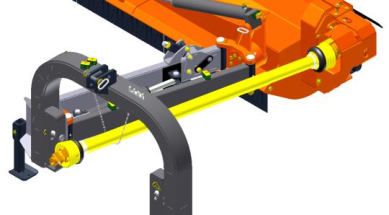
1.4.2 Obstacle Safety Device
If the mowing head hits a fixed obstacle, the tilting piece on the pivot arm can be
pulled over its dead center, extending the arm and pivoting the cutting head freely
backwards. When the arm is extended, it must be retracted immediately, otherwise
the PTO will make too great an angle and damage will result.
The arm can be retracted by reversing at an appropriate driving speed with the cutting
head on the ground. This causes the arm to be retracted and the tilting piece to tilt
back into its basic position.
The collision protection is set at the factory, but can be adjusted by the customer.
By removing rings, the spring tension will become lighter and the tilting piece
will tip over faster when there is resistance. If rings are added, the spring tension
increases and it will therefore be more difficult to tip over with resistance.
1.4.3 Cutting height
The cutting height can, if necessary, be adjusted as follows:
By re-setting the fixing bolts in one of the other adjusting holes of the frame. The
highest hole in the frame will give you the lowest cut (approx. 35 mm, 1½”) and the
lowest hole in the frame the highest cut (approx. 90 mm, 3½”).
1.4.4 P.T.O. shaft
The The P.T.O. shaft (with star formed profile tubes), supplied with the machine, has a retracted length of ± 1820 mm (6').
This length is correct for most of the popular tractor sizes. However it is strongly recommended to check the proper length
of the P.T.O. shaft before operating the machine, and if necessary to shorten it according to the instructions attached to the
P.T.O. shaft.
The machine is designed for a tractor P.T.O. speed of 540 R.P.M. as indicated on the protection cover of the gearbox.
The guard tube of the P.T.O. shaft must be secured against rotation by the little chains.
9Attention: Do not lift the machine when the cutter head is in a right up standing position ánd the mower is in full
offset position. (the P.T.O. shaft will swing under the 3-point bow).
Before operating the machine you must check if the P.T.O. shaft does not touch the 3-point bow in any offset
position. If necessary you must install an extension shaft on the tractor P.T.O. shaft
Remark: Using an oversized tractor it is recommended to install a overload clutch.
This overload clutch should be adjusted at 850 Nm (7.500 inlb)
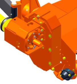
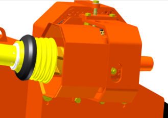
1.4.5 Gearbox
To protect oil to drain, the breather is replaced by a plastic plug during transport from the manufacturer to the farmer. Before
taking the machine in service the plastic plug must be replaced by the breather. During transport the breather is fixed to the
drive shaft of the gearbox.
1.4.6 Transport
During road-transport the machine is carried by the tractor 3-point linkage.
It is not allowed to carry the machine in offset position during road-transport!
1.5 Precautions
Every time before you take the machine in service the following items have to be checked:
• The machine and the tractor checked for operational and road safety
• That all bolts and nuts are sufficiently tight. Retighten if necessary
• Oil level in gearbox (chapter 1.7)
• V-belt tension (chapter 1.8)
• Condition of flails (chapter 1.9)
• Grease points (chapter 1.10)
1.6 Driving speed
Depending on vegetation and working conditions the recommended driving speed is
3 – 6 km./h. (1,5 – 3,5 M.P.H.)
1.7 Gearbox
Before operating the machine and further at regular intervals (at least every 50 hours), the following points should be
checked:
- Oil level:
this is correct when the oil just reaches the hole of the oil level plug (green
arow).
- Breather:
should be free of obstruction. The cap must be slightly compressible. Clean
by blowing through from the inside(red arow).
Renew oil after the first 20 working hours and further after every 100 working hours, but at least once a season.
To renew the gearbox oil handle as follows:
Remove the breather and the drain plug and drain the oil.
*** Collect the old oil, e.g. in a bucket, for environment friendly disposal. ***
Refit the oil drain-plug and pour 1 liter (± 1/2 gallon) diesel-oil through the breather hole in the housings. Clean the internal
gearbox (by washing with the diesel oil) by turning the V-belt pulley a few times by hand.
Then drain and collect the dirty diesel-oil and refill the gearbox to the required oil-level and refit the breather.
Fill up only to the proper level and use always the same oil.
Recommended is synthetic gear-oil EP-320.
10*** Note: Allow the oil enough time to sink through the bearings.
Wipe off excess oil to prevent it reaching the V-belts as oil and grease cause unnecessary slipping and extra wear.
Refill the gearbox to required oil level and refit the breather. Fill up only to the proper level.
ZW – 150, ZW – 180, ZW – 210: oil contents ± 0,75 liter
ZW – 240: oil contents ± 1,25 liter
ZW – Front: oil contents ± 1,25 liter
To replenish or replace the correct oil, if possible Mobil EP 320 or an equivalent oil.
Viscosity base oil at 40°C 320 Cst.
Temperature range -24°C tot 240°C
Good EP properties.
1.8 V-Belts
A correct V-belt tension is very important and must be checked prior to use and after 2, 8
and 16 hours for proper adjustment. Thereafter you should check the tension at regular
intervals, at least every 50 hours.
The V-belts do have the right pré-tension when can displace the V-Belts (one by one)
7,5mm with a force of 8kg (what you can push with your thumb) .
The control opening for the "push-pin" do you find at the rear side of the V-belt housing.
The V-belts of the machine are tensioned a bolt. With this bolt the gearbox is moved
until the correct belt tension is reached. Before changing the V-belts, it must be
completely relaxed.
First loosen the 6 bolts (red arrow) of the gearbox plate, so that it can slide. Then move
the gearbox with the bolt (green arrow) so that the V-belts are tensioned.
Finally retighten the bolts of the gearbox plate.
Remark: When new V-belts are mounted, always make a test run and check the V-belt tension again!!!
1.9 Flails
1.9.1 General
• Only using original Perfect parts will assure you of a safe service of the flail chopper. So use by replacement only
original PERFECT parts.
• Every time before the machine is taken in service the flails should be checked. Are no flails lost? Replace the flails if
necessary by original Perfect parts, see also chapter 1.9.4.
• Check if the flails are not broken or cracked.
• When the fixing bolts have to be replaced you should always use original Perfect bolts M20 x 90, quality 10.9.
• Use the original Perfect lock washers and fasten the lock-nuts with a torque of 550 Nm (4.750 inlb.).
• The flails have to be replaced when there is no longer any overlap.
11No risks !!!
No experiments with imitation parts, use only original Perfect parts !
1.9.2 In service
When the flail mower starts to vibrate the tractor P.T.O. shaft should be disengaged immediately. Check the condition of the
flail rotor and flails.
Replace broken or damaged parts by original PERFECT parts.
1.9.3 P.T.O. / flail rotor speed
Always speed up the P.T.O. shaft to the prescribed speed of 540 RPM before starting to cut
1.9.4 Replacement of flails
• Remove the lock-nuts.
• Replace flails and also the fixing bolts, lock washers and the lock-nuts.
• Use always original PERFECT parts.
• Fasten the lock-nuts with a torque of 550 Nm (4.750 inlb).
1.10 Service
Before operating the machine check if all points as stated below have been greased properly. Lubricate as follows:
1.10.1 P.T.O. shaft
- Profile tubes:
Lubricate every 4 hours of operation. The grease nipple is marked
with an arrow.
Wash the profile tubes clean periodically in order to remove dirt
and accumulated contaminated grease.
- Guard tubes:
Lubricate every 25 hours of operation.
- Yoke crosses:
Lubricate every 8 hours of operation the grease nipples.
- Slide pins:
Oil regularly the pin.
- Overrunningclutch:
Lubricate every 8 hours of operation the grease nipples.
1.10.2 Bearing houses / flail rotor
Lubricate every 8 hours of operation. Always use a good
quality ball bearing grease EP-2, or equivalent.
Wipe off excess grease to prevent it reaching the V-belts as oil
and grease cause unnecessary slipping and extra wear.
121.10.3 Frame pivot point
To be re-lubricate every 8 hours of operation. Articulating arm suspension
1.10.4 Articulating arm
To be re-lubricate every 8 hours of operation.
Articulating arm suspension
1.10.5 Rear roller
To be re-lubricate every 8 hours of operation. Always use a good quality ball
bearing grease EP-2, or equivalent.
If possible lubricate with Total Lical EP/ ELF EPEXELF 2 or an equivalent grease.
Viscosity base oil 40°C 190 - 220 Cst.
Thickener Lithium/Calcium compatible.
Temperature range -25°C tot 130°C
Good EP properties..
1.11 Important advises
1.11.1 Winter services
It is important when taking the flail mower out of service for a longer period, to carry out the following:
• release tension of V-belts
• re-new the gearbox oil (see chapter 1.7)
• check the balance and/or renew flails if necessary
• check which parts have to be replaced or repaired
• wash and clean the machine completely, lubricate the bearings and store it in a dry place.
1.11.2 Repair
Urgent repairs and parts supplies are expensive. Why not use the winter months to bring your machine in a ”Perfect“
condition for the next season.
131.11.3 Torque Moments bolt connections
Bolt connections must through, DIN 267, following list tightened, although is remarked in the manual or parts list.
Size Moment Nm, Class 8.8 Moment Nm, Class 10.9
M8 25 35
M10 50 70
M12 85 120
M14 135 190
M16 210 300
M18 290 410
M20 410 570
1.11.4 Caution
No persons, other than the tractor driver, should be near the flail chopper (less than 100 m) whilst it is in
operation. Never walk close to the rear of the machine.
The tractor driver should never leave the tractor seat before disengaging the tractor P.T.O. shaft, stopping the
engine and pulling the tractor key out.
Never remove guards when the machine is operating.
Never touch the machine before all parts ( P.T.O. shaft, flail rotor, belts and pulleys) have stopped rotating
completely.
This machine is supplied for use in agriculture for topping of pastures, maintenance of fallow land, road sides,
parking lots, airstrips etc.
1.12 Fault table
As a result of normal use, parts will be wear out. (for example Flails and V-belts).
Pay Attention: only use original PERFECT parts that are listed in the parts book.
Failure Causes Solution
Strong vibration and too much Flails not evenly worn out Change flails, complete with bolt and
noise nut as a pair or as complete set
(more) Flails are fixed and don’t Clean the Machine so that the flails
move can be move.
One or more flails are lost or Change flails.
broken
Thread or other stuff wrapped Remove pollution
around the flail rotor.
Flail rotor not in balans Check the rotor / bearings and when is
necessary, must it be balanced
14Bearings of Flail rotor are worn Change bearings and / or flails
out
PTO shaft isn’t in line Change PTO shaft
Machine and or mow quality Machine isn’t horizontal Check rear roller and / or upper
won’t work very well adjusted with the bottom linkage adjustment. When is necessary
add it in the correct way
Flails are worn out Klepels compleet met bouten en
moeren vervangen
Speed flail rotor too low Increase PTO speed
Rijsnelheid te hoog Reduce speed
V-belt tension too low Check V-belt tension and retension if
necessary
V-belt is worn out Change complete set V-belts
Cutting height too low adjusted Check rear roller adjustment and
change that when necessary
Cutting height too high adjusted Check rear roller adjustment and
change that when necessary
Flail rotor won’t rotate Flail rotor is stuck through Remove dirt and clean the machine
pollution
Overrunning clutch in PTO shaft Change overrunning clutch PTO shaft
or Gearbox is wrong or broken. or gear box
PTO goes constantly through
overrunning.
PTO shaft runs, but flail rotor V-belt broken Change set V-belts
don’t Overlaoding clutch (Optional) is Adjust the spring package correctly or
wrong adjusted or worn out change the clutch plates
Rear roller turns heavily or is Rear roller bearings broken or Changes bearings and grease these to
blokked filled with mud the correct level
Running dry, without grease Grease bearings until the grease
comes outside
Dirt between roller and scraper Remove dirt and clean the machine
V-belt problems ( too much V-belts not correct adjusted Check V-belt adjustment and when
belts are worn out, belts burns needed adjust it correctly
out, power transmission isn’t Pulleys not correct in line Align the pulleys correctly
optimal) Cutting height too low adjusted Check rear roller adjustment and
change that when necessary
Gearbox overheated Oil level low Olie tot pijp aanvullen
Oil too old Tandwielkast reinigen en olie
verversen
Flail rotor / machine is Slow down speed and or check rear
overloaded roller adjustment
Oil loss from gearbox Oil seal(s) damaged / worn out Change oil seal(s)
Machine has Machine has high Cutting height too low adjusted Check rear roller adjustment and
wear and tear change that when necessary
No original parts – vibrations in Fit original PERFECT parts
machine
Break off / bend parts Machine is involved in a collision Change defect parts and when
or damaged by pollution necessary must the flail rotor
balanced
151.13 Safety stickers
• The fast rotating flail rotor is protected at the front by clacks and at the rear by the machine-wide carrier roller.
• The warning stickers affixed to the machine provide important instructions for the correct use of the machine.
Check the warning label for presence and observe it
Nr. 50 + Nr. 51
Nr. 53 + Nr. 54
Nr. 50, Carefully read the
infstruction manual and follow safety
instructions.
Nr. 52, Only touch machine after it has come
to a complete standstill.
Danger of turning parts: In case of a running
Nr. 51, Before maintenance or machine keep a distance of at least
reparations, switch off the engine and 100m
take out the key.
Wear Ear and Eye protection.
Nr. 54, Stay out of the turning reach
of the machine, keep a considerable
distance.
1.14 Declaration of Conformity
See next page
16EG-Declaration of Conformity for
machinery
in accordance with the Machine Directive II A
We Van Wamel B.V.
Energieweg 1
6658 AE Beneden-Leeuwen
The Netherlands
Tel. : + 31 487 592944
Fax : + 31 487 592970
Email : perfect@vanwamel.nl
Declare under our sole responsibility that the following product flail chopper
ZW-
To which this declaration relates, is in compliance with the relevant harmonised directive standard:
2006/42/EG
List of subtitles and references harmonised standards under Directive 2006/42/EG for Machinery:
EN ISO 13857:2008, EN 349:1993 + A1:2008, EN 745:1999 + A1:2009,
EN ISO 12100:2010
Responsible for documentation: René van Ravensteijn.
Address see manufacturer.
Beneden-Leeuwen, January 2019 ........................................................
M.M.G. van Ravensteijn
Manager Engineering
17MANUEL D'INSTRUCTION
Multi Broyeur
Modèle ZW
Version V.03
Avant la première mise en marche de la faucheuse "Perfect", lisez attentivement toutes les instructions et faites en sorte
que toutes les mesures de précaution mentionnées ci-dessous soient prises.
Dans le présent manuel, tous les sujets concernant votre sécurité sont marqués avec ce symbole. Tout utilisateur
de la machine doit être mis au courant de ces instructions et précautions.
Dans votre commande de pièces détachées, veuillez mentionner le modèle et le numéro de la machine ainsi que le numéro et la
désignation de la pièce désirée comme indiqué dans le catalogue. Nous vous conseillons de noter dans la déclaration de
conformité (page 64) le modèle et le numéro de la machine comme indiqué sur sa plaque signalétique.
Nous vous souhaitons bon travail avec votre multi broyeur "PERFECT"!
© Copyright 01-01 2019 Van Wamel B.V.
5051
◼ Table des matières

1. MANUEL D'INSTRUCTION ................................................................................................................................................... 53
   1.1 Généralités ................................................................................................................................................................ 53
     1.1.1    Identification ................................................................................................................................................... 53
     1.1.2    Utilisation conforme de la machine ................................................................................................................ 53
   1.2 Prescriptions de sécurité ........................................................................................................................................... 54
     1.2.1    Généralités ...................................................................................................................................................... 54
     1.2.2    Transmission à cardan..................................................................................................................................... 55
     1.2.3    Entretien .......................................................................................................................................................... 55
   1.3 Caractéristiques techniques ...................................................................................................................................... 56
   1.4 Mise en marche ........................................................................................................................................................ 56
     1.4.1    Accouplement au tracteur ............................................................................................................................... 56
     1.4.2    Protection contre les collisions ....................................................................................................................... 56
     1.4.3    Réglage de la hauteur de coupe....................................................................................................................... 57
     1.4.4    Cardan de transmission / Régime de rotation et vitesse de prise de force ...................................................... 57
     1.4.5    Boîte de renvoi d’angle ................................................................................................................................... 57
     1.4.6    Transport ......................................................................................................................................................... 58
   1.5 Mesures de précaution .............................................................................................................................................. 58
   1.6 De conduite .............................................................................................................................................................. 58
   1.7 Boîte de renvoi d’angle ............................................................................................................................................ 58
   1.8 Courroies .................................................................................................................................................................. 59
   1.9 Marteaux................................................................................................................................................................... 59
     1.9.1    Généralités ...................................................................................................................................................... 59
     1.9.2    Utilisation ....................................................................................................................................................... 60
     1.9.3    Régime et vitesse de la prise de force / des marteaux ..................................................................................... 60
     1.9.4    Remplacement des marteaux .......................................................................................................................... 60
   1.10 Entretien, graissage/lubrification .............................................................................................................................. 60
     1.10.1 Cardan de transmission ................................................................................................................................... 60
     1.10.2 Rotors / Boîtes ................................................................................................................................................ 60
     1.10.3 Point charnière ................................................................................................................................................ 60
     1.10.4 Bras d'articulation ........................................................................................................................................... 61
     1.10.5 Rouleau arrière ................................................................................................................................................ 61
   1.11 Avis important .......................................................................................................................................................... 61
     1.11.1 Après la saison de travail ................................................................................................................................ 61
     1.11.2 Réparations ..................................................................................................................................................... 61
   1.13 Etiquettes adhésives relatives à la sécurité ............................................................................................................... 64
   1.14 Déclaration de Conformité ........................................................................................................................................ 64

                                                                                        52
1. Manuel d'instruction
PRESCRIPTIONS GÉNÉRALES DE SÉCURITÉ
Dans le présent manuel tous les sujets concernant votre sécurité sont marqués avec ce symbole. Tout utilisateur de la
machine doit être mis au courant de ces instructions et précautions.
1.1 Généralités
1.1.1 Identification
La désignation de la machine se compose de deux lettres et d'un chiffre. Les lettres, dans ce cas "ZW", indiquent qu'il
s'agit d'un broyeur tondeuse à fléaux qui convient pour la tonte des bords de champs, des bords de route, etc.
- Ces machines sont soutenues à l'arrière par un large rouleau porteur autonettoyant.
- Le chiffre après les lettres ZW indique la largeur de travail de la machine en centimètres.
- Ces machines peuvent éventuellement être équipées de:
➢ Différents types de marteaux.
➢ «Pro-Fix» montages des marteaux.
➢ Version frontal.
1.1.2 Utilisation conforme de la machine
• Observer strictement les avertissements apposés sur la machine.
• Les machines ZW ne doivent être utilisées que pour les travaux pour lesquels elles ont été construites ; (utilisation
conforme de la machine)
- broyage dès l’herbe dans aires de stationnement, aérodromes, prairies, espaces verts etc.
- broyage des broussailles et autres végétations jusqu’à 30 mm de diamètre
- broyage des tiges de maïs
• En cas de dommage lié à l’utilisation de la machine hors du cadre des applications spécifiées par Van Wamel B.V., la
responsabilité de celui-ci sera entièrement dégagée.
• Toute utilisation de la machine hors du cadre de la destination d’origine se fera aux risques et périls de l’utilisateur.
• Les machines ZW ne doivent être utilisées, entretenues et réparées que par des personnes compétentes, familiarisées avec
les caractéristiques et modes d’utilisation des machines. Ces personnes doivent aussi être informées des dangers
auxquels elles pourraient être exposées.
• L’utilisation conforme de la machine implique également:
- le respect des prescriptions d'utilisation, d’entretien et de maintenance spécifiées par le constructeur;
- l’utilisation exclusive de pièces de rechange, d’équipements et d’accessoires d’origine ou préconisés par le
constructeur.
• Van Wamel B.V. décline toute responsabilité en cas de modifications de la machine effectuées par l’utilisateur lui-même
ou toute autre personne, sans l’accord écrit préalable de Van Wamel B.V. L'utilisateur sera entièrement tenu responsable
des conséquences de telles modifications
• L’utilisateur est tenu au respect scrupuleux de la réglementation en vigueur en matière de :
- sécurité du travail (code du travail)
- circulation sur la voie publique (code de la route)
• Il est fortement déconseillé d'utiliser la machine sur des terrains raboteux. Les pierres et objets lourds et/ou massifs
peuvent gravement endommager la machine, créant en outre des situations dangereuses.
- éviter les terrains raboteux
- éviter le passage de cailloux ou autres objets solides sous la machine
Avant la mise en route de la machine et le démarrage des travaux, contrôler les abords immédiats
(présence d'enfants et/ou d'animaux).Eloigner toute personne ou tout animal de la zone de danger, 100 m,
de la machine (risques de projections ! ! !).
53RÈGLE PRINCIPALE
Avant chaque utilisation et mise en service de l’ensemble tracteur-machine, s’assurer de sa conformité
avec la réglementation en matière de sécurité du travail et avec les dispositions du code de la route.
1.2 Prescriptions de sécurité
1.2.1 Généralités
1. Outre les instructions contenues dans cette notice, respecter la législation relative aux prescriptions de sécurité et de
prévention des accidents.
2. Les avertissements apposés sur la machine indiquent les mesures de sécurité à observer et contribuent à éviter les
accidents.
3. Lors de la circulation sur la voie publique, respecter les règles du Code de la Route.
4. Avant de s'engager sur la voie publique, veiller à la mise en place et au bon fonctionnement des protecteurs et
dispositifs de signalisation (lumineux, réfléchissants...) exigés par la loi.
5. Avant de commencer le travail, l'utilisateur doit toujours se familiariser avec les organes de commande et de
manœuvre de la machine et leurs fonctions respectives. En cours de travail, il sera trop tard pour le faire.
6. L'utilisateur doit éviter de porter des vêtements flottants qui risqueraient d'être happés par des éléments en mouvement.
7. L'accouplement de la machine au tracteur ne doit se faire que sur les points d'attelage prévus à cet effet conformément
aux normes de sécurité en vigueur.
8. Avant d'atteler la machine, s'assurer que le lestage de l'essieu avant du tracteur sera suffisant. La mise en place des
masses de lestage doit se faire sur les supports prévus a cet effet conformément aux prescriptions du constructeur du
tracteur.
9. Respecter la charge d'essieu maximum et le poids total roulant autorisé en charge. Respecter le maximum autorisé pour
la circulation sur la voie publique.
10. Lors de l'attelage et de la dépose de la machine, placer la ou les béquilles dans la position prévue.
11. La prudence est de rigueur lors de l'attelage de la machine au tracteur et lors du désaccouplement.
12. Ne pas se tenir entre le tracteur et la machine sans avoir préalablement serré le frein d'arrêt et / ou avoir placé des cales
sous les roues et arrêter la prise de force.
13. Avant chaque utilisation de la machine, contrôler le serrage des vis et des écrous, en particulier de ceux qui fixent les
outils (couteaux, boîtier, patins, palier). Resserrer si nécessaire.
14. Attention !
Des zones d'écrasement et de cisaillement peuvent exister sur les organes commandés à distance, notamment sur les
organes à commande hydraulique ou pneumatique.
Ne pas se tenir dans la zone de manœuvre de la machine.
15. Avant de s'engager sur la voie publique, placer la machine en position de transport, conformément aux indications du
constructeur (position axiale).
16. Toutes les commandes à distance (corde, câble, tringle) doivent être positionnées de telle sorte qu'elles ne puissent pas
déclencher accidentellement une manœuvre pouvant provoquer un accident ou des dégâts.
17. Avant toute utilisation de la machine, s'assurer que tous les dispositifs de protection sont en place et en bon état. Les
protecteurs endommagés doivent être immédiatement remplacés.
18. La vitesse et le mode de conduite doivent toujours être adaptés aux terrains, routes et chemins. En toute circonstance,
éviter les brusques changements de direction.
19. La précision de la direction, l'adhérence du tracteur, la tenue de route et l'efficacité des dispositifs de freinage sont
influencés par des facteurs tels que : poids et nature de la machine attelée, lestage de l'essieu avant, état du terrain ou de
la chaussée.
Il est donc impératif de veiller au respect des règles de prudence dictées par chaque situation.
20. Redoubler de prudence dans les virages en tenant compte du porte-à-faux, de la longueur, de la hauteur et du poids de
la machine.
21. Le transport de personnes ou d'animaux sur la machine lors du travail ou lors des déplacements est strictement interdit.
22. Avant la mise en route de la machine et le démarrage des travaux, contrôler les abords immédiats (enfants!).Veiller à
avoir une visibilité suffisante ! Eloigner toute personne ou animal de la zone de danger de la machine (risques de
projections !).
23. Ne jamais quitter le poste de conduite lorsque le tracteur est en marche.
24. Avant de descendre du tracteur ou avant toute intervention sur la machine, couper le moteur, retirer la clé de contact et
attendre l'arrêt complet de toutes les pièces en mouvement.
25. Utiliser un tracteur équipé d'une cabine de sécurité. Laisser les vitres de la cabine fermée pendant l'utilisation de la
machine.
26. Avant toute intervention sur la machine, s'assurer que celle-ci ne pourra être mise en route accidentellement.
27. Afin de limiter les risques d'incendie, nous vous conseillons de nettoyer régulièrement la machine, également sous les
54capots de protection. Les capots de protection doivent ensuite être refixés avec les boulons d'origine.
28. Avant l’utilisation de la machine vérifiez s’il n’y a pas de fuites d’huile. Elles peuvent affecter le fonctionnement de la
machine et endommager la machine/son environnement.
1.2.2 Transmission à cardan
1. N'utiliser que les arbres de transmission à cardan fournis avec la machine ou recommandés par le constructeur.
2. Les protecteurs des prises de force et des arbres de transmission à cardan doivent toujours être en place et en bon état.
3. Également en cas d'utilisation d'un accouplement à roue libre, il doit y avoir un chevauchement minimum de 50 mm
entre le capot de protection et le protecteur de prise de force.
4. Veiller au recouvrement correct des tubes des arbres de transmission à cardan, aussi bien en position de travail qu'en
position de transport.
5. Si l'arbre de transmission à cardan est équipé d'un limiteur de couple ou d'une roue libre, ceux-ci doivent
impérativement être montés sur la prise de force de la machine.
6. Avant de connecter ou de déconnecter un arbre de transmission à cardan, débrayer la prise de force, couper le moteur
et retirer la clé de contact.
7. Veiller toujours au montage et au verrouillage correct des arbres de transmission à cardan.
8. Veiller toujours à ce que les protecteurs des arbres de transmission à cardan soient immobilisés à l'aide des chaînettes
prévues à cet effet.
9. Avant d'embrayer la prise de force, s'assurer que le régime choisi et le sens de rotation de la prise de force sont
conformes aux prescriptions du constructeur.
10. Avant d'embrayer la prise de force, s'assurer qu'aucune personne ou animal ne se trouve à proximité de la machine.
11. Ne jamais embrayer la prise de force lorsque le moteur du tracteur est coupé.
12. Débrayer la prise de force lorsque les limites angulaires de l'arbre de transmission à cardan prescrites par le
constructeur risquent d'être dépassées.
13. Attention!
Après le débrayage de la prise de force, les éléments en mouvement peuvent continuer à tourner pendant quelques
instants.
Ne pas s'en approcher avant l'immobilisation totale.
14. Lors de la dépose de la machine, faire reposer les arbres de transmission à cardan sur les supports prévus à cet effet.
15. Après avoir déconnecté l'arbre de transmission de l’arbre de la prise de force du tracteur, recouvrir avec le capuchon
protecteur l’arbre prise de force côté tracteur.
16. Les protecteurs de prise de force et d'arbres de transmission à cardan endommagés doivent être réparés / remplacés
immédiatement.
17. Avant d'effectuer des travaux de lubrification, d'entretien ou de réglage sur une prise de force ou sur une machine
entraînée par prise de force, toujours débrayer la prise de force, couper le moteur du tracteur et retirer la clé de contact.
1.2.3 Entretien
1. Avant de procéder à travaux de maintenance, d'entretien ou de réparation, ainsi que lors de la recherche de l'origine
d'une panne ou d'un incident de fonctionnement, toujours débrayer la prise de force, couper le moteur et retirer la clé
de contact.
2. Contrôler régulièrement le serrage des vis et des écrous. Resserrer si nécessaire!
3. Avant de procéder à des travaux d'entretien sur une machine en position relevée, étayer celle-ci à l'aide d'un moyen
approprié.
4. Lors du remplacement d'une pièce, mettre des gants de protection et utiliser un outillage approprié.
5. Pour la protection de l'environnement, il est interdit de jeter ou de déverser les huiles, graisses et filtres en tous genres.
Les confier à des entreprises de récupération spécialisées.
6. Avant toute intervention sur le circuit électrique, déconnecter la source d'énergie.
7. Les dispositifs de protection susceptibles d'être exposés à une usure doivent être contrôlés régulièrement. Les
remplacer immédiatement s'ils sont endommagés.
8. Les pièces de rechange doivent répondre aux normes et caractéristiques définies par le constructeur. N'utiliser que des
pièces de rechange "PERFECT".
En utilisant des pièces d'origine Perfect, vous avez la garantie de conformité.
9. Avant d'entreprendre des travaux de soudure électrique sur le tracteur ou la machine attelée, débrancher les câbles de
l'alternateur et de la batterie.
10. Les réparations affectant les organes sous tension ou pression (ressorts, accumulateurs de pression, etc.) impliquent une
qualification suffisante et font appel à un outillage réglementaire. Ces réparations sont par conséquent réservées à un
personnel qualifié.
55You can also read


