Adaptive Control of Vehicle Active Suspension Based on Neural Network Optimization
←
→
Page content transcription
If your browser does not render page correctly, please read the page content below
E3S Web of Conferences 261, 03046 (2021) https://doi.org/10.1051/e3sconf/202126103046
ICEMEE 2021

 Adaptive Control of Vehicle Active Suspension Based on Neural
 Network Optimization
 Runqi Qiu1*
 1School of International Education, Wuhan University of Technology, Hubei, Wuhan, 430070, China

 Abstract. An adaptive proportional–integral–derivative (PID) control method based on radial basis function
 neural network optimization (RBF-PID) is designed for a four-degree-of-freedom active suspension model of
 a 1/2 vehicle. By building a simulation model of the suspension in MATLAB/Simulink, a C-level road white
 noise random excitation signal is used as the road input, and the front and rear body vertical accelerations are
 simulated as the feedback of the control loop, respectively. The simulation results show that the proposed
 RBF-PID control strategy can effectively suppress the front and rear body acceleration and effectively reduce
 the centroid vertical acceleration, and improve the performance by about 10.3% compared with the traditional
 PID control suspension and about 31.2% compared with the passive suspension, but the control effect
 improvement for the angular acceleration of body pitch angle is not obvious.

 1 Introduction while putting forward various control theories. In recent
 years, many scholars have started to apply neural network
 Nowadays, with the rapid development of the automobile control systems to suspension control and achieved good
 industry, people's requirements for car performance are control result with the help of their strong learning ability
 also increasing, and the comfort and stability of the car and high robustness.
 have become the primary consideration when people buy However, most of the studies on active suspension
 a car. The comfort and stability are closely related to the control strategy are based on the two-degree-of-freedom
 performance of automobile suspension. In the process of model of 1/4 car, ignoring the influence of front and rear
 vehicle driving, the car's suspension will actively absorb suspension vertical motion on the body pitch angle.
 the vibration brought by the road to enhance the comfort Therefore, in this paper, an RBF-PID controller is
 of passengers and the stability of the owner's operation. designed based on a four-degree-of-freedom model of a
 The traditional passive suspension of the automobile 1/2 car, and the front and rear body vertical accelerations
 is composed of a shock absorber and spring. Once the are used as the feedback of the controller to adjust the
 damping coefficient of the damper and the stiffness of the active suspension dynamics, respectively. The simulation
 spring are determined, it is difficult to adjust dynamically results show that the method improves the suspension
 according to the working conditions and cannot react performance, but there is still some room for
 differently under different road conditions. However, the improvement.
 road conditions encountered by the car are changing
 during the driving process, so the suspension has to be
 adjusted accordingly to fit the actual driving conditions of 2 System Description
 the car. Active suspension is a good solution to the
 problem of non-adjustable passive suspension parameters. 2.1. System Description
 The ECU of the car understands the body motion
 condition through the acceleration sensors all over the Since the vehicle is a complicated vibration model, it is
 body and adaptively adjusts the suspension performance essential to simplify the system based on the analysed
 so that the suspension system can be continuously limited problem. Although the 2-DOF quarter vehicle model has
 in an optimal damping state. For this reason, active a simple structure, it can only indicate the vertical
 suspension systems have become a hot topic in suspension acceleration and velocity. The 7-DOF full vehicle model
 system research today. Based on the passive suspension, can characterize the vertical, roll as well as pitch motions,
 the active suspension adds an actuator that dynamically but it is too sophisticated for the designing of the
 adjusts the actuation force to provide a main force inverse controller. Considering the difficulty of system modelling,
 to the body impact load at any time to counteract the controller design as well as simulation, this paper will
 impact from the road, thus achieving the damping effect. adopt the 4-DOF half vehicle model as the plant.
 Since the middle and late 19th century, experts and In these research, four assumptions have been
 scholars have done a lot of research on control strategies, established on the suspension system:

 *Corresponding author: qiurunqi@whut.edu.cn
© The Authors, published by EDP Sciences. This is an open access article distributed under the terms of the Creative Commons Attribution License 4.0
(http://creativecommons.org/licenses/by/4.0/).

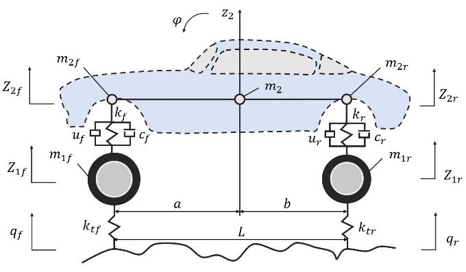
E3S Web of Conferences 261, 03046 (2021) https://doi.org/10.1051/e3sconf/202126103046
ICEMEE 2021

 - The suspension can be simplified to a spring-mass- of the sprung mass of the front and rear suspension can be
 damper system. expressed as follows:
 - The connection between the wheel and the axle and
 the connection between the body and the seat can be (5)
 simplified to a rigid connection.
 - The tire can be regarded as a linear spring without (6)
 damping and assured to contact the road when driving. When the actuation force and are both zero, the
 - The vehicle makes a uniform linear motion in the active suspension system becomes a passive suspension
 longitudinal direction. system.
 The simplified half-car model is shown in Fig.1, in The parameters used for the half-vehicle suspension
 which sprung mass and represent the mass of model are presented in Table 1.
 vehicle body distributed on the front axle and the rear Table 1. System Parameters
 axle, respectively. The equivalent stiffness coefficient of
 the tire is and . and represent the damping Parameters Value Unit
 ratio of the linear damper and the stiffness of the linear 975.37 kg
 spring is and . The vehicle has a moment of inertia
 98 kg
 of and pitch angle of . The actuation force and
 is acting between the car body and the tire. Front axle and 98 kg⋅m2
 rear axle distances with the centre of gravity are and . 1674 kg⋅m2
 and stands for the vertical displacement of the 45.48 kN/m
 sprung mass, while and represent that of the
 52.59 kN/m
 unsprung mass.
 604.69 kN/m
 985.97 kN/m
 2546.5 N⋅s/m
 2840.6 N⋅s/m
 1.1135 m
 1.5415 m
 L 2.655 m

 2.2. Road Excitation Model
 Based on the free body diagram and Newton's second law,
 Fig. 1. Half-Vehicle Active Suspension Model the following system dynamic differential equation can be
 obtained:
 Based on the free body diagram and Newton's second
 law, the following system dynamic differential equation 2 d (7)
 can be obtained:

 2 d (8)
 The vertical displacement of the C-level road profile
 (1) is used as the input signal to the suspension system. The
 0
 road profile roughness coefficient 256
 10 m3. is the uniformly distributed white noise.
 Assuming that the driving speed 20m/s and the rear
 0 (2) wheel input have a 0.1-second delay compared with the
 front wheel. Let the spatial reference frequency of the
 road excitation 0.1m-1 and set the simulation time to
 10s, the road input response of the front and rear wheels
 (3) can be obtained, as shown in Fig.2.
 0

 (4)
 0

 When the pitch angle of the body is small, tan is
 approximately equal to . Thus, the vertical displacement
 Fig. 2. Road Excitation of Front and Rear Wheel

 2

E3S Web of Conferences 261, 03046 (2021) https://doi.org/10.1051/e3sconf/202126103046
ICEMEE 2021

 3 Controller Design Let the theoretical output of the discriminative system
 at time is yout , and the output of this identification
 Conventional PID controllers rely heavily on precise network is ymout , then the performance index
 mathematical models of the controlled objects, which is function of the network is:
 considered to be of low efficiency when applied to 1
 suspension systems. In contrast, neural networks have the (11)
 2
 superior nonlinear fitting ability and are suitable for Let be the moment factor and be the learning rate.
 vehicle suspension, a complex controlled object that is According to the gradient descent method, the iterative
 difficult to model accurately. Therefore, this paper algorithm of weight factor , the node centre vector and
 improves the traditional PID controller based on neural the node base width parameter can be obtained as
 network and selects the RBF network to design the RBF- follows:
 PID controller combining RBF and PID to achieve the
 adaptive adjustment of controller parameters as well as 1 ℎ
 improving the control accuracy. 1 (12)
 2
 3.1. RBF Network

 RBF neural network is a three-layer feedforward network Δ ℎ (13)
 composed of an input layer, a hidden layer, and an output
 layer. Since the mapping of the input to the output is
 1 Δ 1
 nonlinear and the mapping from the hidden layer to the (14)
 output layer is linear, the local minimum problem of the 2
 BP neural network with the same feedforward
 characteristic can be avoided, and the learning speed can Δ (15)

 be greatly improved.
 The topology of the RBF neural network based on
 1 Δ 1
 Gaussian basis functions is shown in Fig.3. In this (16)
 2
 network, the input vector of the network is
 , ,⋯, and the radial basis vector of the hidden
 layer is ℎ ,ℎ ,⋯,ℎ ,⋯,ℎ , where ℎ is the 3.2. PID Parameters Tuning Based on RBF
 Gaussian basis function.
 RBF-PID uses the incremental PID control method:

 Δ 1
 2 1 (17)
 2

 Δ (18)
 Where is the control error,
 . For the active suspension, represents the
 desired front and rear vertical acceleration of the vehicle
 body.
 The Three inputs to the controller are:

 Fig. 3. RBF Neural Network
 1 1 (19)

 2 (20)
 X C
 ℎ exp , j 1,2,3, ⋯ , m (9) 3 2 1 2 (21)
 2b
 The Gain parameters , and of the PID are
 In the equation, is the centre vector of the th node adjusted using the gradient descent method.
 in the network, , ,⋯, ,⋯, ; Let
 Δ
 , ,⋯, ,⋯, , being the base width parameter (22)
 of the hidden layer node and satisfies 0.
 1
 Assuming that the weight vector of the network is
 , , ⋯ , , , the output of the network can
 be obtained: Δ
 (23)

 ℎ 1
 (10)

 3
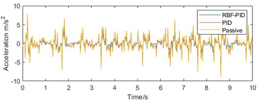
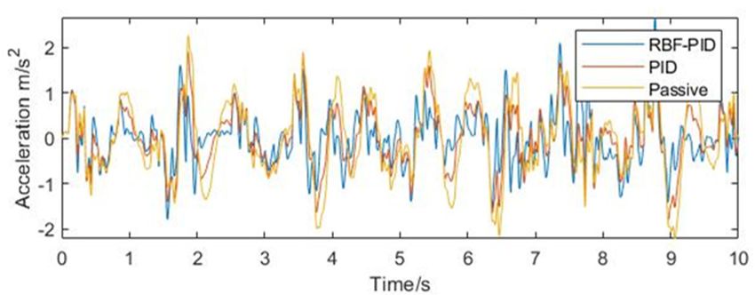
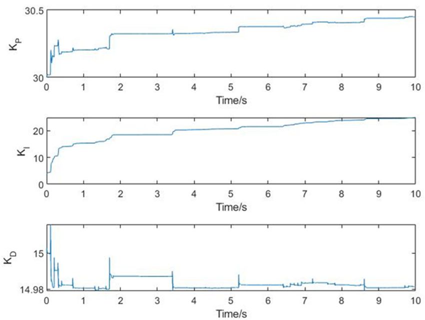
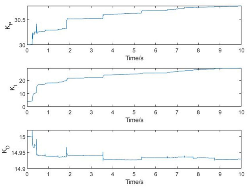
E3S Web of Conferences 261, 03046 (2021) https://doi.org/10.1051/e3sconf/202126103046
ICEMEE 2021

 Δ
 (24)

 1

 Where / is the Jacobian information of the
 controlled object, that is, the sensitivity of the output to
 the input, which can be obtained by the recognition of the
 neural network as follows:

 ℎ (25)

 Based on the above mathematical principles, the RBF-
 PID controller can be established in MATLAB/Simulink
 as shown in Fig.4.
 Fig. 6. Rear Controller Parameter Changes

 4.2. Controller Performance Comparison
 In the simulation experiment, this paper focuses on the
 vehicle body centroid vertical acceleration and pitch angle
 acceleration. Among them, the centre-of-mass
 acceleration characterizes the intensity of body vibration
 when driving on uneven road, and this index mainly
 affects the ride comfort of the vehicle; the pitch angle
 acceleration characterizes the body nodding or lifting
 Fig. 4. RBF-PID Controller
 caused by the vehicle during emergency braking or rapid
 acceleration, and this situation will cause the driver and
 4 Data Analysis and Comparisons passenger to lean back and forward, which affects the ride
 comfort.
 The vertical acceleration of the front and rear bodies
 4.1. System Simulation was simulated as the feedback of the closed-loop control,
 and the output results of the passive suspension were
 The learning rate and the moment factor of the RBF
 compared with the output results of the RBF-PID-
 neural network are real numbers that greater than 0 and
 controlled suspension and PID-controlled suspension as
 less than 1. Take 0.25 and 0.05 and set the
 well as passive suspensions under the same road input in
 number of hidden layer nodes to 6 based on experience.
 the same coordinate system, and the simulation results are
 The gain parameters of the PID controller are set to
 shown in Fig.7 to Fig.10.
 55, 14, 1.5. The adaptive adjustment of the
 PID gain parameters optimized by the RBF neural
 network with the change of the road input is shown in
 Fig.5 and Fig.6.

 Fig. 7. Front Body Vertical Acceleration

 Fig. 8. Rear Body Vertical Acceleration
 Fig. 5. Front Controller Parameter Changes

 4
E3S Web of Conferences 261, 03046 (2021) https://doi.org/10.1051/e3sconf/202126103046
ICEMEE 2021

 of the front and rear ends of the vehicle as well as the
 acceleration of the centre of mass, the control of the
 angular acceleration of the pitch angle of the vehicle is not
 satisfactory. The next research will try to use the MPC
 algorithm to solve the coupling relationship between the
 front and rear suspensions, and if the effect is significant,
 then we will start the test based on the real car.

 Fig. 9. Centroid Acceleration References
 1. Zhang, M.G., Li, W.H., Liu, M.Q. (2005) Adaptive
 PID Control Strategy Based on RBF Neural Network
 Identification. In: 2005 International Conference on
 Neural Networks and Brain, Beijing.pp. 1854-1857.
 2. Ikenaga, S., Lewis, F.S., Davis, L. (2000) Active
 suspension control of ground vehicle based on a full-
 vehicle model. In: 2000 American Control
 Conference, Chicago.pp. 4019-4024.
 Fig. 10. Pitch Angle Acceleration 3. Thompson, A.G., Davis, B.R. (1992) Optimal Active
 Calculating the root mean square values of the three Suspension Design Using a Frequency-shaping PID
 and analysing the dispersion of the data, the results shown Filter. Vehicle System Dynamics, 1: 19-37
 in Table 2 can be obtained.
 4. Khan, L., Qamar, S., Khan U. (2016) Adaptive PID
 Table 2. Simulation Results control scheme for full car suspension control.
 Journal of the Chinese Institute of Engineers, 2: 169-
 185.
 Passive 1.7728 2.2876 0.8566 0.4672 5. Zhang, M.G., Wang, X.G., L, M.Q. (2005) Adaptive
 PID control based on RBF neural network
 PID 1.4530 1.8783 0.6576 0.4619
 identification. In: 17th IEEE International
 RBF-PID 1.1122 1.2619 0.5896 0.5683 Conference on Tools with Artificial Intelligence.
 Hong Kong. pp. 3 pp.-683.
 As can be seen from Table 2, compared with the 6. Lin, J., Lian, R. (2011) Intelligent Control of Active
 passive suspension and PID-controlled suspension, the Suspension Systems. IEEE Transactions on
 controller designed in the thesis has a very obvious Industrial Electronics, 2 :618-6228.
 improvement in reducing the vertical vibration velocity
 under random road input, which effectively improves the
 ride comfort and handling stability performance of the
 vehicle. However, the pitch angle acceleration
 improvement is not obvious, probably because the
 coupling relationship between the two is not taken into
 account when establishing the control loops for the front
 and rear suspensions separately.

 5 Conclusion
 In this paper, an RBF-PID-based active suspension with
 adaptively tuned parameters is designed. The parameters
 of the PID controller are adaptively adjusted online by
 RBF-PID to achieve a stable output of the system. The
 active suspension is modelled in MATLAB/Simulink, and
 the body vertical acceleration and body angular
 acceleration of PID, RBF-PID-controlled suspension, and
 conventional passively controlled suspension are
 compared under C-level random road input. The
 simulation results show that the RBF-PID outperforms the
 PID controller.
 Considering that the controller designed in this study
 uses two separate single loops to control the front and rear
 suspensions respectively, the coupling relationship
 between the two is neglected. Although the controller
 designed in the thesis has good results for the acceleration

 5

You can also read