COMBITAC DIREQT MAIN CATALOG - COMBITAC EN - STAUBLI

Page created by Tyrone Shelton
 
CONTINUE READING
COMBITAC DIREQT MAIN CATALOG - COMBITAC EN - STAUBLI
CombiTac direqt
Main catalog
CombiTac          EN
COMBITAC DIREQT MAIN CATALOG - COMBITAC EN - STAUBLI
STÄUBLI ELECTRICAL CONNECTORS

Long-term solutions – Expert connections

Stäubli Electrical Connectors is a leading     Stäubli develops, produces, sells and ser-         Our customers depend on our expertise and
international manufacturer of high-qual-       vices products for markets with the high-          our active support, even when dealing with
ity electrical contacts and connector          est productivity and safety standards. As          unusual challenges. With Stäubli, you’re en-
systems and solutions for industrial           recognized specialists, our focus is always        tering into a long-term partnership built on
applications. We are part of the Stäubli       on solutions and customers. Many new               reliability, dedication, and exceptional qual-
mechatronics group, the technology             developments got their start here and are          ity in both products and services.
leader in connection solutions, robotics       now becoming established as worldwide
and textile machinery.                         standards.

Pioneering contact technology for in-          distribution sector rely on our consistent,        and reliability of our products are essential
creased efficiency                               loss-free transmission performance in all          for test and measurement technology.
The entire Stäubli Electrical Connectors       voltage ranges. The automotive industry            In the growing field of alternative energy,
product range meets market expectations        depends on our high-efficiency connections         our products have been setting standards
for high performance, the highest number       for spot-welding applications in production        since the 1990s. About half of the solar
of mating cycles, and long-lasting reliabil-   lines. Harsh conditions in the transporta-         energy generated worldwide is transmitted
ity for safe, durable operation. Our proven    tion sector require high vibration resistance,     through safe, long-lasting, high-perfor-
MULTILAM technology is ideal for all types     maximum reliability, and compact design.           mance Stäubli connectors.
of connections in industrial applications.     These attributes are vitally important for rail-
Customers in the power transmission and        way and e-mobility applications. The safety

2   CombiTac direqt main catalog
COMBITAC DIREQT MAIN CATALOG - COMBITAC EN - STAUBLI
Applications and advantages

CombiTac modular connectors com-              CombiTac uniq is designed for more de-         This product catalog is dedicated to the
bine various connection types in a single     manding applications that require versatile    CombiTac direqt product line. To find out
frame or housing and can be configured        long-life modular connector solutions, and     more about CombiTac uniq, please refer to
according to your exact specifications.       where combination of power, signal, data,      the CombiTac uniq main catalog.
Depending on your application needs, two      fiber optic, fluid and pneumatic connections
types of CombiTac products are available,     are needed.                                    Further information concerning prod-
CombiTac direqt and CombiTac uniq.                                                           uct portfolio, special features as well as
                                              CombiTac uniq is 100 % customizable            ­exemplary videos can be found at
CombiTac direqt is ideal for applications     to meet exact technical and dimensional        ­www.combitac.com
where fast tool-free assembly is required,    specifications, and thanks to the tried and
and where it is necessary to combine elec-    tested MULTILAM Technology, its contacts
trical signal, power and pneumatic connec-    can reach up to 100,000 mating cycles and
tions up to 10,000 mating cycles. Particu-    current levels up to 300 A.
larly in applications where a high quantity
of modular connectors for low power and       As a solutions provider, and depending on
signals are needed, CombiTac direqt offers    your business needs, we offer you extensive
significant economic advantages.              A-Z support in configuring your own ­100 %
                                              customized CombiTac modular connector,
                                              including cable assembly if required.

                                                                                                                 CombiTac direqt main catalog   3
COMBITAC DIREQT MAIN CATALOG - COMBITAC EN - STAUBLI
Content
Page 6               The world of CombiTac              Page 24   Single parts
                     • Plug into more possibilities               • Spacers
                     • CombiTac Configurator                      • Frames
                                                                  • For details on      see page 57
Page 10              Ø 10 mm power up to 350 A
                     • Contact carrier                  Page 28   Housings
                     • Contacts                                   • Aluminum housing IP65
                     • For details on     see page 57             • Aluminum housing IP68
                                                                  • Plastic housing IP65
Page 12              Ø 7 mm power up to 120 A
                     • Contact carrier                  Page 48   Crimping pliers
                     • Contacts
                     • For details on     see page 57   Page 49   Appendix
                                                                  • Derating diagrams
Page 14              Ø 3 mm power up to 31 A                      • Technical information
                     • Contact carrier                            • Safety notes
                     • Contacts                                   • Safety situation for CombiTac connectors
                     • For details on     see page 57             • Index

Page 16              Ø 1.5 mm Signal up to 14 A
                     • Contact carrier
                     • Contacts
                     • For details on     see page 57

Page 18              Ø 1 mm Signal up to 5 A
                     • Contact carrier
                     • Contacts
                     • For details on     see page 57

Page 20              Last Mate First Break module
                     • Module
                     • Last Mate First Break contacts
                     • For details on     see page 57

Page 22              Pneumatic 4 mm and 6 mm
                     • Contact carrier
                     • Compressed air couplings

4   CombiTac direqt main catalog
COMBITAC DIREQT MAIN CATALOG - COMBITAC EN - STAUBLI
General information
Changes/provisos                                    Symbols                                                                                              Abbreviations
All data, illustrations, and drawings in the                                                                                                             CTD     = CombiTac direqt
                                                                                                                                       MA
                                                                       Montageanleitung.            zum richtigen Einsatz
                                                                eine                        und
                                                          bin                                                                    des
                                                    Ich
                                                                       mich unbedingt le-                    Im Moment
                                                           sollte                           Produktes.                     ist

catalog have been carefully checked. They
                                                                                                                                 die

                                                                                                                                                         S       = Socket
                                                    Man
                                                                   man das Produkt ver-                 zwar ein bischen
                                                           bevor                            Schrift                         klein,
                                                    sen,
                                                                 Ich beinhalte wertvolle                    geht das dann
                                                                                                   später                    ganz
                                                    wendet!                                 aber

                                                                 zur korrekten Montage                  lesen,
                                                                                                                 da die MA
                                                                                                                           dann
                                                    Hinweise                                       zu
                                                                                            gut

are in accordance with our experience to            The assembly instructions MA000 are                                                                  P       = Pin
date, but no responsibility can be accepted         available for this product                                                                           C       = Carrier
for errors.                                                                                                                                              C       = Crimp termination
We also reserve the right to make modifica-                                                                                                 Surface Ag   PE      = Protective Earth
tions for design and safety reasons. When                                                                                                                FP      = Frame panel
designing equipment incorporating our                                                                                                       Surface Au   FH      = Frame housing
components, it is therefore advisable not                                                                                                                AWG     = American Wire Gauge
to rely solely on the data in the catalog but
to consult us to make sure this information                                                                                                              Aluminum DIN housings IP65
is up to date. It would be our pleasure to                                                                                                               S       = Side cable entry
advise you.                                                                                                                                              T       = Top cable entry
                                                                                                                                                         CH      = Coupler hood
Copyright                                                                                                                                                CHG     = Coupler housing
The use of this catalog for any other pur-                                                                                                               PW      = Protective wall
pose, in whatever form, without our prior                                                                                                                PC      = Protective cover
written consent is not permitted.                                                                                                                        SM      = Surface mount
                                                                                                                                                         PM      = Pedestal mount
                                                                                                                                                         PS      = Park station
 RoHS Conformity
                                                                                                                                                         Aluminum housings IP68/69K,
 European Directive 2011/65/EU (RoHS 2)                                                                                                                  Plastic housings IP65
 Commission Delegated Directive (EU) 2015/863 (RoHS 3)                                                                                                   S       = Side
                                                                                                                                                         G       = Top
 For further information please visit our website                                                                                                        TG      = Coupler hood
 https://ec.staubli.com/downloads/certificates/rohs                                                                                                      AG      = Surface mount
                                                                                                                                                         SG      = Pedestal mount

                                                                                                                                                                             CombiTac direqt main catalog   5
COMBITAC DIREQT MAIN CATALOG - COMBITAC EN - STAUBLI
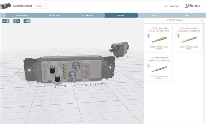
THE WORLD OF COMBITAC

Plug into more possibilities
Experience combined with quality and mod-         demanding requirements. Reliability when
ularity leads to cost-efficient, and durable      you need it. Flexibility, if you want it: The
connection solutions. The modular connec-         world of CombiTac's modular connector
tor system CombiTac can be easily config-         system ­meets your needs.
ured online and adapted to meet the most

               CombiTac direqt

                                                Click & connect
                                                Most assembly-effective
                                                10,000 mating cycles

                                               The latest generation of modular connectors for power, signal, and pneumatic con-
                                               nections up to 10,000 mating cycles. The new user-friendly, tool-free click-and-con-
                                               nect system allows you to assemble your modular connector system in the most
                                               time-saving way.

               CombiTac uniq

                                                100 % customizable
                                                Highest performance
                                                100,000 mating cycles

                                               Modular connectors for power, signal, data, pneumatic and fluid connections up to
                                               100,000 mating cycles. Offers the highest possible performance and can be custom-
                                               ized to meet exact technical and dimensional specifications.

6   CombiTac direqt main catalog
COMBITAC DIREQT MAIN CATALOG - COMBITAC EN - STAUBLI
CombiTac Configurator
The CombiTac Configurator is a web ap-        step by step on various end devices. It also
plication that enables you to put together    allows you to receive a quotation for your
your personalized CombiTac configuration      selected CombiTac modular connector.

                         CombiTac Configurator
                         https://configurator.combitac.com

                                                                                             CombiTac direqt main catalog   7
COMBITAC DIREQT MAIN CATALOG - COMBITAC EN - STAUBLI
COMBITAC DIREQT

The modular connector system
DIN coupler hoods
• 6 different sizes
• IP65, IP68/69K
• Aluminum or plastic
• Available in gray or white

Frames
• 4 sizes for housing or panel mount
• Included in delivery

CombiTac delivery status
• Contact carrier mounted on frames
• Contacts separately

Possible connections
• Electrical signal
• Electrical power
• Protective earth (PE)
• Pneumatic

Cable assembly
• On request

DIN surface and pedestal mount housing
• 6 different sizes
• Aluminum or plastic
• Available in gray or white

Mating cycles
Panel mounted:                     up to 10,000
Housing:                           up to 10,000 depending on type

8   CombiTac direqt main catalog
COMBITAC DIREQT MAIN CATALOG - COMBITAC EN - STAUBLI
CombiTac direqt main catalog   9
COMBITAC DIREQT MAIN CATALOG - COMBITAC EN - STAUBLI
Ø 10 MM POWER UP TO 350 A

Contact carrier CTD-C10-1/...
1-pole contact carriers for 10 mm power                                                                             Features:                                           • Railway-compliant material
contacts.                                                                                                           • Tool-free insertion in frames                     • Resistance to shock and vibrations
                                                                                                                    • Quick removal with standard flat screw-           • Coded carriers for correct insertion
                                                                                                                      driver
CTD-C10-1/S

CTD-C10-1/P

                            Order No.                                                                 Type                           Description

                            35.4101                                                                   CTD-C10-1/S                    Socket carrier
                            35.4100                                                                   CTD-C10-1/P                    Pin carrier
                            35.4109                                                                   CTD-RC10                       Retaining clip (included with carriers)

                            Technical data

                            Number of poles                                                                          1
                            Pollution degree/overvoltage category                                                    2/CAT II                                          3/CAT III
                            Rated voltage, c
                                            rimp termination                                                        600 V                                             300 V
                            Rated voltage UL                                                                         600 V
                            Degree of protection (socket and plug front)                                             IP2X
                            Clearances and creepage distance                                                         IEC 60664-1:2020 and UL 1977
                            Limiting temperature (IEC 61984:2008), u
                                                                    pper                                            +125 °C
                                                                   lower                                             -40 °C
                            Contact carrier material                                                                 PA
                            Fire behaviour                                                                           EN45545-2:2015 (HL2 R22)

                                                                                   MA
                   Montageanleitung.            zum richtigen Einsatz
            eine                        und
      bin                                                                    des
Ich
                   mich unbedingt le-                    Im Moment
       sollte                           Produktes.                     ist
                                                                             die
Man
               man das Produkt ver-                 zwar ein bischen
       bevor                            Schrift                         klein,
sen,
             Ich beinhalte wertvolle                    geht das dann
                                               später                    ganz
wendet!                                 aber

             zur korrekten Montage                  lesen,
                                                             da die MA
                                                                       dann
Hinweise                                       zu
                                        gut

Assembly instructions MA417
www.staubli.com/electrical                                                                                          E229145

10                                                                     CombiTac direqt main catalog
Ø 10 mm contacts
10 mm power contacts up to 350 A.                                      Features:                                                            • MULTILAM Technology in sockets
                                                                       • Tool-free insertion in carriers                                    • IP2X on socket and pin side
                                                                       • Quick removal of contacts through                                  • Resistance to shock and vibrations
                                                                             removal of holding clip                                        • Crimp termination (C) for Cu con-
                                                                                                                                              ductors (class 5 and 6) according to
                                                                                                                                              IEC 60228:2004
CTD-S10/... AG                                   CTD-P10/... AG

                                                                                                Sur­         Conductor                Rated
     Order No.                Type                                Socket           Pin                                                                  Type of termination
                                                                                                face         cross section            current¹⁾

                                                                                                             mm²           AWG2)      A
                                                                                                                                                        C
     35.0153                  CTD-S10/35 AG                       ×
                                                                                                             35            2          180
     35.0553                  CTD-P10/35 IP2X AG                                   ×

                                                                                                                                                        C
     35.0152                  CTD-S10/50 AG                       ×
                                                                                                             50            1/0        225
     35.0552                  CTD-P10/50 IP2X AG                                   ×

                                                                                                                                                        C
     35.0151                  CTD-S10/70 AG                       ×
                                                                                                             70            2/0        290
     35.0551                  CTD-P10/70 IP2X AG                                   ×

                                                                                                                                                        C
     35.0150                  CTD-S10/95 AG                       ×
                                                                                                             95            4/0        350
     35.0550                  CTD-P10/95 IP2X AG                                   ×

     Accessories

                                                                  Shrink tubing 43 mm
     35.5656-04321             CTD-10-SRTU/433)
                                                                  (not included in delivery)

     Technical data

     Nominal-Ø socket/pin                                             10 mm
     Max. sliding force per contact                                   20 N
     Connector resistance                                             < 40 μΩ
     Mating cycles                                                    10,000
     Vibrations and shock                                             IEC 61373:2010 Category 1B

1)
     IEC rated current for fully assembled frames size 4. Wires
     unbundled, free in air. See pages 49 – 52 for corre-
     sponding diagrams for multiple, bundled wires.                    3)
                                                                            Suitable for UL applications: UL-224 125 °C 600 V, file
2)
     To be validated by the end user.                                       E48398

                                                                                                                                                               CombiTac direqt main catalog   11
Ø 7 MM POWER UP TO 120 A

Contact carrier CTD-C7-2/...
2-pole contact carriers for 7 mm power con-                                                                        Features:                                           • Railway-compliant material
tacts.                                                                                                             • Tool-free insertion in frames                     • Resistance to shock and vibrations
                                                                                                                   • Quick removal with standard flat screw-           • Coded carriers for correct polarity inser-
                                                                                                                     driver                                              tion
CTD-C7-2 /S

CTD-C7-2 /P

                            Order No.                                                                 Type                          Description

                            35.4071                                                                   CTD-C7-2/S                    Socket carrier
                            35.4070                                                                   CTD-C7-2/P                    Pin carrier
                            35.4079                                                                   CTD-RC7                       Retaining clip (included with carriers)

                            Technical data

                            Number of poles                                                                         2
                            Pollution degree/overvoltage category                                                   2/CAT II                                          3/CAT III
                            Rated voltage, c
                                            rimp termination                                                       600 V                                             300 V
                            Rated voltage UL                                                                        600 V
                            Degree of protection (socket and plug front)                                            IP2X
                            Clearances and creepage distance                                                        IEC 60664-1:2020 and UL 1977
                            Limiting temperature (IEC 61984:2008), u
                                                                    pper                                           +125 °C
                                                                   lower                                            -40 °C
                            Contact carrier material                                                                PA
                            Fire behaviour                                                                          EN45545-2:2015 (HL2 R22)

                                                                                   MA
                   Montageanleitung.            zum richtigen Einsatz
            eine                        und
      bin                                                                    des
Ich
                   mich unbedingt le-                    Im Moment
       sollte                           Produktes.                     ist
                                                                             die
Man
               man das Produkt ver-                 zwar ein bischen
       bevor                            Schrift                         klein,
sen,
             Ich beinhalte wertvolle                    geht das dann
                                               später                    ganz
wendet!                                 aber

             zur korrekten Montage                  lesen,
                                                             da die MA
                                                                       dann
Hinweise                                       zu
                                        gut

Assembly instructions MA417
www.staubli.com/electrical                                                                                         E229145

12                                                                     CombiTac direqt main catalog
Ø 7 mm contacts
7 mm power contacts up to 120 A.                                       Features:                                            • IP2X on socket and pin side
                                                                       • Tool-free insertion in carriers                    • Resistance to shock and vibrations
                                                                       • Quick removal of contacts through                  • Crimp termination (C) for Cu con-
                                                                           removal of holding clip                            ductors (class 5 and 6) according to
                                                                                                                              IEC 60228:2004

CTD-S7/... AG                                    CTD-P7/... AG

                                                                                        Sur­         Conductor        Rated
     Order No.            Type                                    Socket       Pin                                                      Type of termination
                                                                                        face         cross section    current¹⁾

                                                                                                     mm²      AWG2)   A
                                                                                                                                        C
     35.0144              CTD-S7/6 AG                             ×
                                                                                                     6        10      50
     35.0544              CTD-P7/6 IP2X AG                                     ×

                                                                                                                                        C
     35.0143              CTD-S7/10 AG                            ×
                                                                                                     10       8       70
     35.0543              CTD-P7/10 IP2X AG                                    ×

                                                                                                                                        C
     35.0142              CTD-S7/16 AG                            ×
                                                                                                     16       6       100
     35.0542              CTD-P7/16 IP2X AG                                    ×

                                                                                                                                        C
     35.0141              CTD-S7/25 AG                            ×
                                                                                                     25       4       120
     35.0541              CTD-P7/25 IP2X AG                                    ×

     Technical data

     Nominal-Ø socket/pin                                             7 mm
     Max. sliding force per contact                                   20 N
     Connector resistance                                             < 150 μΩ
     Mating cycles                                                    10,000
     Vibrations and shock                                             IEC 61373:2010 Category 1B

Note:                                                                  must add a protective wall. This ensures
To guarantee IP2X protection when using                                protection of 7 mm contacts against dam-
7 mm contacts in configurations which in-                              age in case housing falls on a hard surface.
clude a housing with side cable entry, you

1)
     IEC rated current for fully assembled frames size 4. Wires
     unbundled, free in air. See pages 49 – 52 for corre-
     sponding diagrams for multiple, bundled wires.
2)
     To be validated by the end user.

                                                                                                                                               CombiTac direqt main catalog   13
Ø 3 MM POWER UP TO 31 A

Contact carrier CTD-C3-3/...
3-pole contact carriers for 3 mm power con-                                                                           Features:                                    • Railway-compliant material
tacts.                                                                                                                • Tool-free insertion in frames              • Resistance to shock and vibrations
                                                                                                                      • Quick removal with standard flat screw-    • Coded carriers for correct polarity insertion
                                                                                                                        driver                                     • PE version with marking

CTD-C3-3/S                                                                                                                                     CTD-C3-2+PE/S

CTD-C3-3/P                                                                                                                                     CTD-C3-2+PE/P

                            Order No.                                                                 Type                             Description

                            35.4031                                                                   CTD-C3-3/S                       Socket carrier
                            35.4030                                                                   CTD-C3-3/P                       Pin carrier
                            35.4035                                                                   CTD-C3-2+PE/S                    Socket carrier with
                            35.4034                                                                   CTD-C3-2+PE/P                    Pin carrier with

                            Technical data
                            Number of poles                                                                            3
                            Pollution degree/overvoltage category                                                      2/CAT II                                   3/CAT III
                            Rated voltage, c
                                            rimp termination                                                          300 V                                      100 V
                            Rated voltage UL                                                                           250 V
                            Degree of protection (socket front)                                                        IP2X
                            Clearances and creepage distance                                                           IEC 60664-1:2020 and UL 1977
                            Limiting temperature (IEC 61984:2008), u
                                                                    pper                                              +125 °C
                                                                   lower                                               -40 °C
                            Contact carrier material                                                                   PA
                            Fire behaviour                                                                             EN45545-2:2015 (HL2 R22)

                                                                                   MA
                   Montageanleitung.            zum richtigen Einsatz
            eine                        und
      bin                                                                    des
Ich
                   mich unbedingt le-                    Im Moment
       sollte                           Produktes.                     ist
                                                                             die
Man
               man das Produkt ver-                 zwar ein bischen
       bevor                            Schrift                         klein,
sen,
             Ich beinhalte wertvolle                    geht das dann
                                               später                    ganz
wendet!                                 aber

             zur korrekten Montage                  lesen,
                                                             da die MA
                                                                       dann
Hinweise                                       zu
                                        gut

Assembly instructions MA417
www.staubli.com/electrical                                                                                            E229145

14                                                                     CombiTac direqt main catalog
Ø 3 mm contacts
3 mm power contacts up to 31 A.                                        Features:                                          • Resistance to shock and vibrations
                                                                       • Tool-free-insertion in carriers                  • Crimp termination (C) for Cu con-
                                                                       • Quick removal with standard flat screw-            ductors (class 5 and 6) according to
                                                                           driver                                           IEC 60228:2004
                                                                       • Long pin PE version available

CTD-S3/2,5-4 AU                                  CTD-P3/2,5-4 AU

CTD-S3/2,5-4 AU                                  CTD-P3/2,5-4/PE AU

                                                                                       Sur­      Conductor         Rated
     Order No.            Type                                    Socket       Pin                                                    Type of termination
                                                                                       face      cross section     current¹⁾

                                                                                                 mm²       AWG2)   A
                                                                                                                                      C
     35.0132              CTD-S3/2,5-4 AU                         ×                              2.5       14      23
     35.0532              CTD-P3/2,5-4 AU                                      ×                 4         12      31

                                                                                                                                      C
                                                                                                 2.5       14
     35.0534              CTD-P3/2,5-4/PE AU                                   ×                                   – 3)
                                                                                                 4         12

     Technical data

     Nominal-Ø socket/pin                                             3 mm
     Max. sliding force per contact                                   4.5 N
     Connector resistance                                             < 1.1 mΩ
     Mating cycles                                                    10,000
     Vibrations and shock                                             IEC 61373:2010 Category 1B

1)
     IEC rated current for fully assembled frames size 4. Wires
     unbundled, free in air. See pages 49 – 52 for corre-
     sponding diagrams for multiple, bundled wires.
2)
     To be validated by the end user.
3)
     Short circuit current 3s
     2.5 mm²: 157 A
     4 mm²: 252 A

                                                                                                                                             CombiTac direqt main catalog   15
Ø 1.5 MM SIGNAL UP TO 14 A

Contact carrier CTD-C1,5-5/...
5-pole contact carriers for 1.5 mm signal                                                                            Features:                                    • Railway-compliant material
contacts.                                                                                                            • Tool-free insertion in frames              • Resistance to shock and vibrations
                                                                                                                     • Quick removal with standard flat screw-    • Coded carriers for correct polarity
                                                                                                                       driver                                       insertion
CTD-C1,5-5/S

CTD-C1,5-5/P

                            Order No.                                                                 Type                            Description

                            35.4021                                                                   CTD-C1,5-5/S                    Socket carrier
                            35.4020                                                                   CTD-C1,5-5/P                    Pin carrier

                            Technical data

                            Number of poles                                                                           5
                            Pollution degree/overvoltage category                                                     2/CAT II                                   3/CAT III
                            Rated voltage, c
                                            rimp termination                                                         150 V                                      100 V
                            Rated voltage UL                                                                          150 V
                            Degree of protection (socket front)                                                       IP2X
                            Clearances and creepage distance                                                          IEC 60664-1:2020 and UL 1977
                            Limiting temperature (IEC 61984:2008), u
                                                                    pper                                             +125 °C
                                                                   lower                                              -40 °C
                            Contact carrier material                                                                  PA
                            Fire behaviour                                                                            EN45545-2:2015 (HL2 R22)

                                                                                   MA
                   Montageanleitung.            zum richtigen Einsatz
            eine                        und
      bin                                                                    des
Ich
                   mich unbedingt le-                    Im Moment
       sollte                           Produktes.                     ist
                                                                             die
Man
               man das Produkt ver-                 zwar ein bischen
       bevor                            Schrift                         klein,
sen,
             Ich beinhalte wertvolle                    geht das dann
                                               später                    ganz
wendet!                                 aber

             zur korrekten Montage                  lesen,
                                                             da die MA
                                                                       dann
Hinweise                                       zu
                                        gut

Assembly instructions MA417
www.staubli.com/electrical                                                                                           E229145

16                                                                     CombiTac direqt main catalog
Ø 1.5 mm contacts
1.5 mm signal contacts up to 14 A.                                     Features:                                        • Resistance to shock and vibrations
                                                                       • Tool-free insertion in carriers                • Crimp termination (C) for Cu con-
                                                                       • Quick removal with standard flat screw-          ductors (class 5 and 6) according to
                                                                           driver                                         IEC 60228:2004

CTD-S1,5/0,75-1,5 AU                             CTD-P1,5/0,75-1,5 AU

                                                                                       Sur­      Conductor         Rated
     Order No.            Type                                    Socket       Pin                                                  Type of termination
                                                                                       face      cross section     current¹⁾

                                                                                                 mm²       AWG2)   A

                                                                                                 0.75      18      8                C
     35.0120              CTD-S1,5/0,75-1,5 AU                    ×
                                                                                                 1.0       18      10
     35.0520              CTD-P1,5/0,75-1,5 AU                                 ×
                                                                                                 1.5       16      14

     Technical data

     Nominal-Ø socket/pin                                             1.5 mm
     Max. sliding force per contact                                   3.5 N
     Connector resistance                                             < 2 mΩ
     Mating cycles                                                    10,000
     Vibrations and shock                                             IEC 61373:2010 Category 1B

1)
     IEC rated current for fully assembled frames size 4. Wires
     unbundled, free in air. See pages 49 – 52 for corre-
     sponding diagrams for multiple, bundled wires.
2)
     To be validated by the end user.

                                                                                                                                           CombiTac direqt main catalog   17
Ø 1 MM SIGNAL UP TO 5 A

Contact carrier CTD-C1-7/...
7-pole contact carriers for 1 mm signal con-                                                                       Features:                                    • Railway-compliant material
tacts.                                                                                                             • Tool-free insertion in frames              • Resistance to shock and vibrations
                                                                                                                   • Quick removal with standard flat screw-    • Coded carriers for correct polarity
                                                                                                                     driver                                       insertion
CTD-C1-7/S

CTD-C1-7/P

                            Order No.                                                                 Type                          Description

                            35.4011                                                                   CTD-C1-7/S                    Socket carrier
                            35.4010                                                                   CTD-C1-7/P                    Pin carrier

                            Technical data

                            Number of poles                                                                         7
                            Pollution degree/overvoltage category                                                   2/CAT II                                   3/CAT III
                            Rated voltage, c
                                            rimp termination                                                       150 V                                      100 V
                            Rated voltage UL                                                                        150 V
                            Degree of protection (socket front)                                                     IP2X
                            Clearances and creepage distance                                                        IEC 60664-1:2020 and UL 1977
                            Limiting temperature (IEC 61984:2008), u
                                                                    pper                                           +125 °C
                                                                   lower                                            -40 °C
                            Contact carrier material                                                                PA
                            Fire behaviour                                                                          EN45545-2:2015 (HL2 R22)

                                                                                   MA
                   Montageanleitung.            zum richtigen Einsatz
            eine                        und
      bin                                                                    des
Ich
                   mich unbedingt le-                    Im Moment
       sollte                           Produktes.                     ist
                                                                             die
Man
               man das Produkt ver-                 zwar ein bischen
       bevor                            Schrift                         klein,
sen,
             Ich beinhalte wertvolle                    geht das dann
                                               später                    ganz
wendet!                                 aber

             zur korrekten Montage                  lesen,
                                                             da die MA
                                                                       dann
Hinweise                                       zu
                                        gut

Assembly instructions MA417
www.staubli.com/electrical                                                                                         E229145

18                                                                     CombiTac direqt main catalog
Ø 1 mm contacts
1 mm signal contacts up to 5 A.                                        Features:                                       • Resistance to shock and vibrations
                                                                       • Tool-free insertion in carriers               • Crimp termination (C) for Cu con-
                                                                       • Quick removal with standard flat screw-          ductors (class 5 and 6) according to
                                                                           driver                                         IEC 60228:2004

CTD-S1/... AU                                    CTD-P1/... AU

                                                                                       Sur­      Conductor         Rated
     Order No.            Type                                    Socket       Pin                                                  Type of termination
                                                                                       face      cross section     current¹⁾

                                                                                                 mm²       AWG2)   A
                                                                                                                                    C
     35.0110              CTD-S1/0,14-0,25 AU                     ×                              0.14      26      2
     35.0510              CTD-P1/0,14-0,25 AU                                  ×                 0.25      24      3

                                                                                                 0.25      24      3                C
     35.0111              CTD-S1/0,25-0,75 AU                     ×
                                                                                                 0.5       20      4
     35.0511              CTD-P1/0,25-0,75 AU                                  ×
                                                                                                 0.75      18      5

     Technical data

     Nominal-Ø socket/pin                                             1 mm
     Max. sliding force per contact                                   1.5 N
     Connector resistance                                             < 3 mΩ
     Mating cycles                                                    10,000
     Vibrations and shock                                             IEC 61373:2010 Category 1B

1)
     IEC rated current for fully assembled frames size 4. Wires
     unbundled, free in air. See pages 49 – 52 for corre-
     sponding diagrams for multiple, bundled wires.
2)
     To be validated by the end user.

                                                                                                                                           CombiTac direqt main catalog   19
LAST MATE FIRST BREAK MODULE

Module CTD-LMFB-...
Last Mate First Break (LMFB) contacts are                                                                                    Note:                                      edge positions of the frame. Empty carri-
intended for monitoring purposes, and show                                                                                   • Size 1 frames require one LMFB module,   er slots (position 2 – 6) may be used with
whether a CombiTac is fully connected or                                                                                       which can be placed in any position in   1 mm signal contacts (page 19).
not. Each CombiTac LMFB module consists                                                                                        the frame.
of two LMFB contacts.                                                                                                        • Size 2 – 4 frames require two LMFB
Suitable for panel mount and housing ap-                                                                                       modules which are positioned at the
plications.

                            Order No.                                                                 Type                                    Description

                            35.4017                                                                   CTD-LMFB-S/0,14-0,25                    Socket module
                            35.4016                                                                   CTD-LMFB-P/0,14-0,25                    Pin module
                            35.4019                                                                   CTD-LMFB-S/0,25-0,75                    Socket module
                            35.4018                                                                   CTD-LMFB-P/0,25-0,75                    Pin module

                            Technical data

                            Number of poles                                                                                   7 (slots 1 and 7 for LMFB contacts)
                            Limiting temperature (IEC 61984:2008), u
                                                                    pper                                                     +125 °C
                                                                   lower                                                      -40 °C
                            Contact carrier material                                                                          PA
                            Fire behaviour                                                                                    EN45545-2:2015 (HL2 R22)

                                                                                   MA
                   Montageanleitung.            zum richtigen Einsatz
            eine                        und
      bin                                                                    des
Ich
                   mich unbedingt le-                    Im Moment
       sollte                           Produktes.                     ist
                                                                             die
Man
               man das Produkt ver-                 zwar ein bischen
       bevor                            Schrift                         klein,
sen,
             Ich beinhalte wertvolle                    geht das dann
                                               später                    ganz
wendet!                                 aber

             zur korrekten Montage                  lesen,
                                                             da die MA
                                                                       dann
Hinweise                                       zu
                                        gut

Assembly instructions MA417
www.staubli.com/electrical                                                                                                   E229145

20                                                                     CombiTac direqt main catalog
Last Mate First Break contacts CTD-LMFB...
To be used with contact carrier ­CTD-C1-7/...    Features:                                          • Resistance to shock and vibrations
for monitoring the connection status of elec-    • Tool-free insertion in carriers                  • Crimp termination (C) for Cu con-
trical contacts Ø 3 mm – Ø 10 mm.                • Quick removal with standard flat screw-            ductors (class 5 and 6) according to
                                                   driver                                             IEC 60228:2004

                                                                                     Sur­    Conductor
 Order No.       Type                                           Socket      Pin                                 Type of termination
                                                                                     face    cross section

                                                                                             mm²       AWG
                                                                                                                C
 35.0112         CTD-LMFB-S1/0,14-0,25 AU                       ×                            0,14      26
 35.0512         CTD-LMFB-P1/0,14-0,25 AU                                   ×                0,25      24

                                                                                             0,25      24       C
 35.0113         CTD-LMFB-S1/0,25-0,75 AU                       ×
                                                                                             0,5       20
 35.0513         CTD-LMFB-P1/0,25-0,75 AU                                   ×
                                                                                             0,75      18

 Technical data

 Rated voltage/system voltage                   UDC 29,5 V
 Max. signal current                            100 mA
 Nominal-Ø socket/pin                           1 mm
 Max. sliding force                             1,5 N
 Connector resistance                           < 3 mΩ
 Mating cycles                                  10,000
 Vibrations and shock                           IEC 61373:2010 Category 1B

Note:
When using carrier positions 2 – 6 with
Ø 1 mm Signal contacts, the technical spe-
cifications of carriers and contacts of pages
18 – 19 apply.

                                                                                                                       CombiTac direqt main catalog   21
PNEUMATIC 4 MM AND 6 MM

Contact carrier CTD-CP-2/...
2-pole contact carriers for pneumatic cou-                                                                         Features:                                   • Railway-compliant material
plings.                                                                                                            • Tool-free insertion in frames             • Resistance to shock and vibrations
                                                                                                                   • Quick removal with standard flat screw-   • Coded carriers for correct polarity
                                                                                                                     driver                                      insertion
CTD-CP-2/S

CTD-CP-2/P

                            Order No.                                                                 Type                              Description

                            35.4121                                                                   CTD-CP-2/S                        Socket carrier
                            35.4120                                                                   CTD-CP-2/P                        Pin carrier

                            Technical data

                            Number of poles                                                                         2
                            Nominal bore (mm)                                                                       03
                            Max. working pressure (bar)                                                             15
                            Min. working pressure (mbar)                                                            14
                            Operating temperatures                                                                  -15 °C ... +90 °C
                            Sealing materials                                                                       NBR
                            Mating cycles                                                                          10,000
                            Contact carrier material                                                                PA
                            Fire behaviour                                                                          EN45545-2:2015 (HL2 R22)

                                                                                   MA
                   Montageanleitung.            zum richtigen Einsatz
            eine                        und
      bin                                                                    des
Ich
                   mich unbedingt le-                    Im Moment
       sollte                           Produktes.                     ist
                                                                             die
Man
               man das Produkt ver-                 zwar ein bischen
       bevor                            Schrift                         klein,
sen,
             Ich beinhalte wertvolle                    geht das dann
                                               später                    ganz
wendet!                                 aber

             zur korrekten Montage                  lesen,
                                                             da die MA
                                                                       dann
Hinweise                                       zu
                                        gut

Assembly instructions MA417
www.staubli.com/electrical

22                                                                     CombiTac direqt main catalog
Compressed air couplings
4 mm and 6 mm pneumatic couplings.                                    Features:
                                                                      • With or without shut-off valve

­CT-B...-RCT03/...                                                      ­CT-S...-RCT03/...

                                                                                                                                Shut-off

                                                                                                    Outer-Ø D                                             Press ring
     Order No.           Type                                               Socket           Plug                        A      without    with
                                                                                                    of the tube                                           color

                                                                                                    mm        "          mm
     33.0180             ­CT-B-RCT03/4                                      ×                       4         ( ⁵⁄₃₂ )   14     ×
     33.0181              ­CT-BV-RCT03/4                                    ×                       4         ( ⁵⁄₃₂ )   14                ×
     33.0580               ­CT-S-RCT03/4                                                     ×      4         ( ⁵⁄₃₂ )   7      ×

     33.0182             ­CT-B-RCT03/6¹⁾                                    ×                       6                    17     ×
     33.0183              ­CT-BV-RCT03/6¹⁾                                  ×                       6                    17                ×
     33.0582               ­CT-S-RCT03/6¹⁾                                                   ×      6                    11.5   ×

1)
     For flow, head loss diagrams, and sliding forces, see page 53.

                                                                                                                                           CombiTac direqt main catalog   23
SINGLE PARTS

Spacers
Dips for filling up empty frame spaces.    Features:                                   • Railway-compliant material
                                           • Tool-free insertion in frames             • Resistance to shock and vibrations
                                           • Quick removal with standard flat screw-
                                               driver

CTD-DIP3,5

 Order No.             Type

 35.4135               CTD-DIP3,5

 Technical data

 Contact carrier material                 PA
 Fire behaviour                           EN45545-2:2015 (HL2 R22)
 Vibrations and shock                     IEC 61373:2010 Category 1B

E229145

24   CombiTac direqt main catalog
Frames
4 types of frames for housings or panel       Features:                                     • Grounding connection up to 6 mm² earth
mount applications.                           • Coded frames for correct polarity during        conductors
                                                  connection (male/female)                      Type of termination: Flat connector
                                              • Coded frames for correct polarity carrier       termination 6.3 mm x 0.8 mm
                                                  insertion                                 • Numbered frames for position identifi-
                                                                                                cation
CTD-FP.../S                                                                                 • Float mounting panel mount frames for
                                                                                                +/- 1 mm misalignment absorption

CTD-FH.../S

 Panel mounted                                                        Housing assembly

 Order No.        Type         Description                            Order No.     Type             Description

 35.4291          CTD-FP1/S    Assembled frame socket side            35.4221       CTD-FH1/S        Assembled frame socket side
 35.4281          CTD-FP1/P    Assembled frame plug side              35.4201       CTD-FH1/P        Assembled frame plug side

 35.4292          CTD-FP2/S    Assembled frame socket side            35.4222       CTD-FH2/S        Assembled frame socket side
 35.4282          CTD-FP2/P    Assembled frame plug side              35.4202       CTD-FH2/P        Assembled frame plug side

 35.4293          CTD-FP3/S    Assembled frame socket side            35.4223       CTD-FH3/S        Assembled frame socket side
 35.4283          CTD-FP3/P    Assembled frame plug side              35.4203       CTD-FH3/P        Assembled frame plug side

 35.4294          CTD-FP4/S    Assembled frame socket side            35.4224       CTD-FH4/S        Assembled frame socket side
 35.4284          CTD-FP4/P    Assembled frame plug side              35.4204       CTD-FH4/P        Assembled frame plug side

 Technical data

 Contact carrier material                    PA
 Fire behaviour                              EN45545-2:2015 (HL2 R22)
 Vibrations and shock                        IEC 61373:2010 Category 1B
                                                                                            E229145

                                                                                                                   CombiTac direqt main catalog   25
CALCULATION OF INSTALLATION DIMENSIONS

Drilling plan
for frame panel mounting

 Size                               Frame size

                                    1            2    3    4
 L1                                 44           57   78   104
 L2                                 63           76   97   123

for frame housing assembly

 Size                               Frame size

                                    1            2    3    4
 A                                  44           57   78   104
 B                                  40           53   74   100
 C                                  38           51   72   98

26   CombiTac direqt main catalog
PANEL MOUNTING

Panel mounting
Max. permissible mounting offset

Max. permissible mounting angular misalignment during mating

Max. permissible distance between the contact carriers when mated

                                                           Contacts   Sizes X

                                                                      max. mm
                                                           CTD 10     6
                                                           CTD 7      6
                                                           CTD 3      6
                                                           CTD 1,5    3
                                                           CTD 1      2
                                                           RCT03      1.5

                                                                      CombiTac direqt main catalog   27
ALUMINUM HOUSINGS INTRODUCTION

Standard DIN housings
Aluminum DIN housings are designed to            Features depending on type (see table     • IP2X during connecting/disconnecting
serve general industrial, healthcare and rail-   page 29 for details):                       process when using protective walls
way applications.                                • Up to 10,000 mating cycles              • Ergonomic locking mechanism
Available in grey and white color depending      • IP65 and IP67 in mated condition        Benefits:
on size. Other colors available upon request.    • 6 coding possibilities                  • Minimum service costs
                                                 • Quick and easy replacement of sealing   • Added user safety
                                                 • Resistance to shock and vibrations      • Low maintenance costs
                                                                                           • Reliable solution
                                                                                           • Easy handling

Coupler hoods/Surface and pedestal mount housings

                                                                                           Coupler hoods
                                                                                           Can be used with a surface or pedestal
                                                                                           mount housing. Available with side or top
                                                                                           cable entry, with or without protective wall.

                                                                                           Surface and pedestal mount housings
                                                                                           Both types are used with coupler hoods.
                                                                                           The choice of mount housing depends on
                                                                                           the cable entry type. Available with or with-
                                                                                           out protective wall or cover.

Accessories
                                                                                           Park stations
                                                                                           • For parking coupler hoods when not in
                                                                                             use

                                                                                           Replacement seals (depending on type)
                                                                                           • Available upon request

28   CombiTac direqt main catalog
Technical data DIN housings
     Technical data

     Housing material                                        Aluminum
     Seal material                                           NBR
     Locking mechanism material                              Stainless steel
     Vibrations and shock                                    IEC 61373:2010 Category 1B

Comparison chart of the different housings
                                                                                                                        Vibrations and      Replaceable
     Size     IP65      IP67      Mating cycles           Color                Temperature range
                                                                                                                        shock               seal

                                                                                                                        IEC 62847:2016
     1        ×                   5,000                   Grey RAL9006         -40 °C to +90 °C
                                                          Grey RAL7012         -40 °C to +125 °C short-term operation
     2        ×         ×         10,000                                                                                ×                   ×
                                                          White RAL9003        -40 °C to +90 °C continuous operation

                                                          Grey RAL7012         -40 °C to +125 °C short-term operation
     3        ×         ×         10,000                                                                                ×                   ×
                                                          White RAL9003        -40 °C to +90 °C continuous operation

                                                          Grey RAL7012         -40 °C to +125 °C short-term operation
     4        ×         ×         10,000                                                                                ×                   ×
                                                          White RAL9003        -40 °C to +90 °C continuous operation
     5        ×                   5,000                   Grey RAL9006         -40 °C to +90 °C
     6        ×                   5,000                   Grey RAL9006         -40 °C to +90 °C

1)
     Follow maintenance instructions according to MA213

                                                                                                                                   CombiTac direqt main catalog   29
ALUMINUM HOUSING IP65

Coupler hood
Coupler hoods can be combined with sur-        Note for sizes 2, 3, 4:
face or pedestal mount housing. Available      For white housing please add the color code
with side or top cable entry.                  number 29, e.g. 33.2362-29. Other colors
                                               available upon request.

                                                                                                               Standard
 Size             Order No.         Type                Cable entry             Sizes (mm)
                                                                                                               color

                                                        Side          Top       A1           A2     A3   A6
                  33.1551           CT-CH1-S            ×
 1                                                                              60           43     72   M32
                  33.1571           CT-CH1-T                          ×
                  33.2402           CT-CH2-S            ×
 2                                                                              73.8         43.9   70   M32      29
                  33.2362           CT-CH2-T                          ×

                  33.2403           CT-CH3-S            ×
 3                                                                              93.8         43.9   76   M32      29
                  33.2363           CT-CH3-T                          ×

                  33.2404           CT-CH4-S            ×
 4                                                                              120.8        43.9   78   M32      29
                  33.2364           CT-CH4-T                          ×

                  33.0365           CT-CH5-S            ×
 5                                                                              95           82.5   79   M40
                  33.0355           CT-CH5-T                          ×

                  33.0366           CT-CH6-S            ×
 6                                                                              131          89     96   M50
                  33.0356           CT-CH6-T                          ×

30   CombiTac direqt main catalog
Coupler housing
Coupler housings can be combined with
coupler hoods. Available with top cable entry.

­CT-CHG...-T

­CT-CHG...-T

                                                                                                                                 Protective                                            Standard
                            Size                                                        Order No.   Type           Cable entry                Sizes (mm)
                                                                                                                                 wall                                                  color

                                                                                                                   Top                        A1      A2     A3     A4    A6
                            1                                                           33.1501     ­CT-CHG1-T     ×                          60      43     75     20    M32
                                                                                        33.5082     CT-CHG2-T
                            2                                                                                      ×                          73      43     74     35    M32
                                                                                        33.5092     CT-CHG2-T/PW                 ×
                                                                                        33.5083     CT-CHG3-T
                            3                                                                                      ×                          93.5    43     80     35    M32
                                                                                        33.5093     CT-CHG3-T/PW                 ×

                                                                                        33.5084     CT-CHG4-T
                            4                                                                                      ×                          120     43     82     35    M32
                                                                                        33.5094     CT-CHG4-T/PW                 ×
                            5                                                           33.0415     CH-CHG5-T      ×                          95      82.5   82.5   33    M40

                                                                                   MA
                   Montageanleitung.            zum richtigen Einsatz
            eine                        und
      bin                                                                    des
Ich
                   mich unbedingt le-                    Im Moment
       sollte                           Produktes.                     ist
                                                                             die
Man
               man das Produkt ver-                 zwar ein bischen
       bevor                            Schrift                         klein,
sen,
             Ich beinhalte wertvolle                    geht das dann
                                               später                    ganz
wendet!                                 aber

             zur korrekten Montage                  lesen,
                                                             da die MA
                                                                       dann
Hinweise                                       zu
                                        gut

Assembly instructions MA213
www.staubli.com/electrical

                                                                                                                                                                         CombiTac direqt main catalog   31
Coupler hood with protective wall, IP2X
Coupler hoods with protective walls of-       Note for sizes 2, 3, 4:
fer additional damage protection to con-      For white housing please add the color code
tacts along with IP2X protection during the   number 29, e.g. 33.2362-29. Other colors
­connecting/disconnecting process. Protec-    available upon request.
tive walls are in black.

CT-CH...PW

CT-CH...PW-PC

32   CombiTac direqt main catalog
Standard
Size       Order No.      Type                    Cable entry         Sizes (mm)
                                                                                                                  color

                                                  Side          Top   A1           A2     A3     A6
           33.2952        CT-CH2-S/PW             ×
2                                                                     78.5         51.5   86.5   M32                   29
           33.2912        CT-CH2-T/PW                           ×
           33.2953        CT-CH3-S/PW             ×
3                                                                     99           51.5   92.5   M32                   29
           33.2913        CT-CH3-T/PW                           ×

           33.2954        CT-CH4-S/PW             ×
4                                                                     125.2        51.5   94.5   M32                   29
           33.2914        CT-CH4-T/PW                           ×

           33.3255        CT-CH5-S/PW             ×
5                                                                     101          91     95.5   M40
           33.3275        CT-CH5-T/PW                           ×

           33.3256        CT-CH6-S/PW             ×
6                                                                     136          98.5   121    M50
           33.3276        CT-CH6-T/PW                           ×

for use with housings that include protective covers

           33.2972        CT-CH2-S/PW-PC          ×
2                                                                     78.5         51.5   86.5   M32                   29
           33.2932        CT-CH2-T/PW-PC                        ×

           33.2973        CT-CH3-S/PW-PC          ×
3                                                                     99           51.5   92.5   M32                   29
           33.2933        CT-CH3-T/PW-PC                        ×

           33.2974        CT-CH4-S/PW-PC          ×
4                                                                     125.2        51.5   94.5   M32                   29
           33.2934        CT-CH4-T/PW-PC                        ×

           33.3295        CT-CH5-S/PW-PC          ×
5                                                                     101          91     95.5   M40
           33.3225        CT-CH5-T/PW-PC                        ×

           33.3296        CT-CH6-S/PW-PC          ×
6                                                                     136          98.5   121    M50
           33.3226        CT-CH6-T/PW-PC                        ×

                                                                                                      CombiTac direqt main catalog   33
Surface mount housing
Surface mount housings are used for bot-       Coupler hoods with protective walls of-       Note for sizes 2, 3, 4:
tom cable entry. They are combined with        fer additional damage protection to con-      For white housing please add the color code
coupler hoods and are available with or        tacts along with IP2X protection during the   number 29, e.g. 33.2362-29. Other colors
without protective wall or cover. Protective   ­connecting/disconnecting process.            available upon request.
walls are in black.

CT-SM...

CT-SM...PW

CT-SM...PC

34   CombiTac direqt main catalog
Protective   Protective                                              Standard
Size   Order No.   Type                                  Sizes (mm)
                               cover        wall                                                    color

                                                         A1      A2     A3     A4      A5
       33.1561     CT-SM1                                                              –
1                                                        82      43     29     20
       33.1591     CT-SM1-PC   ×                                                       26.5

       33.2302     CT-SM2                                        44.9   28.5   32.9    –
2      33.2852     CT-SM2/PW                ×            94      51.5   41.4   29.6    –                 29
       33.2332     CT-SM2-PC   ×                                 44.9   28.5   32.9    29.8

       33.2303     CT-SM3                                        44.9   28.5   32.9    –
3      33.2853     CT-SM3/PW                ×            114     51.5   41.4   29.6    –                 29
       33.2333     CT-SM3-PC   ×                                 44.9   28.5   32.9    29.8

       33.2304     CT-SM4                                        44.9   28.5   32.9    –
4      33.2854     CT-SM4/PW                ×            141     51.5   41.4   29.6    –                 29
       33.2334     CT-SM4-PC   ×                                 44.9   28.5   32.9    29.8

       33.0375     CT-SM5                                        90     36     27      –
5      33.3235     CT-SM5/PW                ×            124     91.2   52     26.4    –
       33.0385     CT-SM5-PC   ×                                 90     36     27      22

       33.0376     CT-SM6                                                              –
6                                                        165     90     38.5   50
       33.0386     CT-SM6-PC   ×                                                       25

                                                                                      CombiTac direqt main catalog   35
Pedestal mount housing
Pedestal mount housings are used for left        Pedestal mount with protective walls of-      Note for sizes 2, 3, 4:
and/or right side cable entry. They are com-     fer additional damage protection to con-      For white housing please add the color code
bined with coupler hoods and are available       tacts along with IP2X protection during the   number 29, e.g. 33.2362-29. Other colors
with or without protective wall or cover. Pro-   ­connecting/disconnecting process.            available upon request.
tective walls are black.

CT-PM...

CT-PM...PW

CT-PM...PC

36   CombiTac direqt main catalog
Protective   Protective                                                     Standard
Size   Order No.   Type                                  Sizes (mm)
                               cover        wall                                                           color

                                                         A1      A2     A3     A4     A5      A6
       33.1541     CT-PM1                                                             –
1                                                        82      54.5   74     13.5           M32
       33.1581     CT-PM1-PC   ×                                                      20

       33.2462     CT-PM2                                               74            –
2      33.2872     CT-PM2/PW                ×            94      57     86.9   26.9   –       M32               29
       33.2702     CT-PM2-PC   ×                                        74            23.8

       33.2463     CT-PM3                                               77            –
3      33.2873     CT-PM3/PW                ×            117     57     90     26.9   –       M32               29
       33.2703     CT-PM3-PC   ×                                        77            23.8

       33.2464     CT-PM4                                               79            –
4      33.2874     CT-PM4/PW                ×            144     57     92     26.9   –       M32               29
       33.2704     CT-PM4-PC   ×                                        79            23.8

       33.1025     CT-PM5                                        84     78.5          –
5      33.2085     CT-PM5/PW                ×            126     92.5   92.8   33     –       M32
       33.1035     CT-PM5-PC   ×                                 84     78.5          22

       33.0396     CT-PM6                                                             –
6                                                        140     120    98.5   37             M40
       33.0406     CT-PM6-PC   ×                                                      10

                                                                                             CombiTac direqt main catalog   37
Park stations
Used for parking coupler hoods when they   Note for sizes 2, 3, 4:
are not connected to mount housings.       For white housing please add the color code
                                           number 29, e.g. 33.2362-29. Other colors
                                           available upon request.

CT-PS...SM/P

CT-PS...SM/S

CT-PS...PC-SM/S

38   CombiTac direqt main catalog
Pin end      Socket end   Protective                                            Standard
 Size      Order No.    Type                                                    Sizes (mm)
                                         pieces       pieces       cover                                                 color

                                                                                A1    A2     A3     A4        A5
           34.0340      CT-PS1-SM/P      ×
 1                                                                              82    43     29     21
           34.0341      CT-PS1-SM/S                   ×

           33.1802      CT-PS2-SM/P      ×
 2         33.1812      CT-PS2-SM/S                   ×                         94    44.9   28.5   32.9      29.8            29
           33.1832      CT-PS2/PC-SM/S                ×            ×

           33.1803      CT-PS3-SM/P      ×
 3         33.1813      CT-PS3-SM/S                   ×                         114   44.9   28.5   32.9      29.8            29
           33.1833      CT-PS3/PC-SM/S                ×            ×

           33.1804      CT-PS4-SM/P      ×
 4         33.1814      CT-PS4-SM/S                   ×                         141   44.9   28.5   32.9      29.8            29
           33.1834      CT-PS4/PC-SM/S                ×            ×

           34.0354      CT-PS5-SM/P      ×
 5         34.0355      CT-PS5-SM/S                   ×                         124   84     36     33        22
           34.0358      CT-PS5/PC-SM/S                ×            ×

           34.0356      CT-PS6-SM/P      ×
 6         34.0357      CT-PS6-SM/S                   ×                         165   90     38.5   50        25
           34.0359      CT-PS6/PC-SM/S                ×            ×

Replacement seals
Replacement housing seals made of NBR
can be reordered.

CT-DDI-SM...                                 CT-PDI-SM...

 Size       Order No.    Type                     Description

 2          33.2782      CT-DDI-SM2
 3          33.2783      CT-DDI-SM3               Upper seal
 4          33.2784      CT-DDI-SM4
 2          33.2792      CT-PDI-SM2
 3          33.2793      CT-PDI-SM3               Lower seal
 4          33.2794      CT-PDI-SM4

                                                                                                           CombiTac direqt main catalog   39
Selection of special DIN housings for
CombiTac Ø 10 mm contacts
Step 1: Select the number of Ø 10 mm                                     Step 3: Select the appropriate cable gland
poles of your CombiTac connector (e.g. 2 ×                               (e.g. order No. 33.4126 or 33.4122)
Ø 10 mm pole)
                                                                         Step 4: Select a suitable DIN housing (e.g.
Step 2: Select the outer insulation diameter                             size 3, order No. 33.2713)
of your cable ​(e.g. 17 mm)

        1                                2            3                                                              4
                                                      Cable gland                                                    Suitable housing
     Number of poles

                                                                                                                                                           of cable glands
                                                                                                       Wrench size
                                       For Ø cable

                                                             Order No.

                                                                                                                            Order No.

                                                                                                                                                           Position
                                                                         Type

                                                                                                                                        Type
                                                                                                       max.
                                                      Size

                                                                                                                     Size
                                         mm           M                                                 mm
                                         9.5 – 12.5           33.4120    CT-K-VSH M25x9,5-12,5 MS       30
                                         10 – 17      25      33.4126    CT-K-VSH M25x10-17 MS          28           2       33.1571    CT-CH1-T
                                         16 – 20.5            33.4122    CT-K-VSH M25x16-20,5 MS        30
        1
                                         14 – 17              33.4123    CT-K-VSH M32x14-17 MS
                                         17 – 21      32      33.4124    CT-K-VSH M32x17-21 MS          36           2       33.2362    CT-CH2-T
                                         21 – 25              33.4125    CT-K-VSH M32x21-25,5 MS
                                         9.5 – 12.5           33.4120    CT-K-VSH M25x9,5-12,5 MS       30
                                         10 – 17      25      33.4126    CT-K-VSH M25x10-17 MS          28           3       33.2713    CT-CH3-T/2xM25
        2
                                         16 – 20.5            33.4122    CT-K-VSH M25x16-20,5 MS        30
        (+/-)
                                         14 – 17              33.4123    CT-K-VSH M32x14-17 MS
        (L1/N)
                                         17 – 21      32      33.4124    CT-K-VSH M32x17-21 MS          36           4       35.1204    CT-CH4-T/2xM32
                                         21 – 25              33.4125    CT-K-VSH M32x21-25,5 MS
                                         9.5 – 12.5           33.4120    CT-K-VSH M25x9,5-12,5 MS       30
                                         10 – 17      25      33.4126    CT-K-VSH M25x10-17 MS          28           4       33.2744    CT-CH4-T/3xM25
        3
                                         16 – 20.5            33.4122    CT-K-VSH M25x16-20,5 MS        30
        (+/-/PE)
                                         14 – 17              33.4123    CT-K-VSH M32x14-17 MS
        (L1/N/PE)
                                         17 – 21      32      33.4124    CT-K-VSH M32x17-21 MS          36           6       35.1206    CT-CH6-T/3xM32
                                         21 – 25              33.4125    CT-K-VSH M32x21-25,5 MS

        4                                9.5 – 12.5           33.4120    CT-K-VSH M25x9,5-12,5 MS       30
        (L1/L2/L3/PE)                    10 – 17      25      33.4126    CT-K-VSH M25x10-17 MS          28           5       33.3175    CT-CH5-T/4xM25
        (L1/L2/L3/N)                     16 – 20.5            33.4122    CT-K-VSH M25x16-20,5 MS        30

        5                                9.5 – 12.5           33.4120    CT-K-VSH M25x9,5-12,5 MS       30
        (L1/L2/L3 /                      10 – 17      25      33.4126    CT-K-VSH M25x10-17 MS          28           6       33.3186    CT-CH6-T/6xM251)
        N/PE)                            16 – 20.5            33.4122    CT-K-VSH M25x16-20,5 MS        30

1)
        Close one gland opening with cap (not provided).

40                CombiTac direqt main catalog
ALUMINUM HOUSING IP68/69K

Coupler hood
                                                                        The all-round contact of the two hous-
                                                                        ing halves of the IP68/69K enclosures
                                                                        provides a 360° shielding against elec-
                                                                        tromagnetic influence according to
                                                                        VG 95373-41.

Size   Order No.   Type                Cable entry         Sizes (mm)

                                       Side          Top   A1           A2             A3                  A6
       33.6871     ­ T-TG1-S IP68 HE
                   C                   ×
1                                                          132          58             100.5               M32
       33.6881     ­CT-TG1-G IP68 HE                 ×

       33.6872     ­ T-TG2-S IP68 HE
                   C                   ×
2                                                          144          58             100.5               M32
       33.6882     CT-TG2-G IP68 HE                  ×

       33.6873     ­ T-TG3-S IP68 HE
                   C                   ×
3                                                          164          58             110.5               M40
       33.6883     CT-TG3-G IP68 HE                  ×

       33.6874     CT-TG4-S IP68 HE    ×
4                                                          191          58             110.5               M40
       33.6884     CT-TG4-G IP68 HE                  ×

Surface mount housing

Size   Order No.   Type                Sizes (mm)

                                       A1                        A2                     A3
1      33.6851     ­CT-AG1 IP68 HE     132                       58                     29.5
2      33.6852     ­CT-AG2 IP68 HE     144                       58                     29.5
3      33.6853     ­CT-AG3 IP68 HE     164                       58                     29.5
4      33.6854     CT-AG4 IP68 HE      191                       58                     29.5

                                                                                             CombiTac direqt main catalog   41
Pedestal mount housing

 Size             Order No.         Type              Sizes (mm)

                                                      A1           A2   A3      A6
 1                33.6861           ­CT-SG1 IP68 HE   156          80   100.5   2×M25
 2                33.6862           ­CT-SG2 IP68 HE   169          80   100.5   2×M32
 3                33.6863           ­CT-SG3 IP68 HE   189          80   111.5   2×M32
 4                33.6864           CT-SG4 IP68 HE    216          80   111.5   2×M40

Protective cap

 Size             Order No.         Type

 1                33.6891           CT-PC1 IP68 HE
 2                33.6892           CT-PC2 IP68 HE
 3                33.6893           CT-PC3 IP68 HE
 4                33.6894           CT-PC4 IP68 HE

42   CombiTac direqt main catalog
PLASTIC HOUSING IP65

Plastic DIN housing
The plastic housing is primarily intended for    In addition, the plastic housing is mechan-
industrial use or for applications where a       ically robust.
high resistance to chemical environmental        As the housing is made of antistatic ther-
influences is required.                          moplastic material, there is no need for ad-
                                                 ditional grounding.

 Technical data

 Housing material                               Thermoplastic
 Housing seal                                   Elastomer
 Locking element                                Thermoplastic
 Degree of protection mated/locked              IP65

                                                                                                CombiTac direqt main catalog   43
Plastic housing – Resistance to aggressive media                   Plastic housing – Resistance to aggressive media

                                           Resistant   Limited                                              Resistant   Limited
                                                       resistance                                                       resistance

 1-Pentanol                                            x            Glycerol                                x
 Alum                                      x                        Grinding oil                                        x
 Amide, aqueous                            x                        Gypsum (see calcium sulfate)            x
 Ammonia gas                                           x            Heptane                                             x
 Ammonia, 10 % aqueous solution            x                        Hexane                                              x
 Ammonium acetate                          x                        Hydrogen sulfide                                    x
 Ammonium carbonate                        x                        Ink                                     x
 Ammonium chloride                         x                        Isopropyl alcohol                                   x
 Ammonium nitrate                          x                        Lactic acid                             x
 Ammonium phosphate                        x                        Linseed oil                             x
 Ammonium sulfate                          x                        Lubricating oil                         x
 Aniline                                               x            Mercury                                 x
 Asphalt                                               x            Methanol, diluted by 50 %                           x
 Beer                                      x                        Mineral oil                             x
 Borated water                             x                        Mineral spirits (Avio)                              x
 Borax                                                 x            Mineral-based oil                       x
 Boric acid, 10 % aqueous solution         x                        Mothballs                                           x
 Boric acid                                x                        Motor oil                                           x
 Butane gas                                            x            n-Butanol                               x
 Butane, liquid                                        x            Naphthalene                                         x
 Calcium chloride, 10 % aqueous solution   x                        Octane                                              x
 Calcium chloride                          x                        Oil IRM 901, 20 °C                      x
 Calcium nitrate                           x                        Oil IRM 902, 20 °C                                  x
 Calcium sulfate                           x                        Oil IRM 903, 20 °C                                  x
 Chlorinated lime, diluted                 x                        Oil                                                 x
 Copper sulfate, 10 % aqueous solution     x                        Oleic acid                              x
 Cresol acids                                          x            Oxalic acid                             x
 Cresol solution                                       x            Paraffin oil                            x
 Cutting oil                                           x            Petroleum                               x
 Cyclohexane                                           x            Phthalate                               x
 Diesel                                                x            Potassium carbonate                     x
 Diisononyl phthalate                      x                        Potassium chlorate                      x
 Di-Octyl-Phthalate                        x                        Potassium chloride                      x
 Diluted glucose                           x                        Potassium chromate                                  x
 Diluted glycerol                          x                        Potassium cyanide, aqueous solution     x
 Diluted glycol                            x                        Potassium iodide                                    x
 Diluted phenol                                        x            Potassium nitrate                                   x
 Ethanol, non-denaturized                  x                        Potassium persulfate                                x
 Ethylene glycol or propylene glycol       x                        Potassium sulfate                                   x
 Fatty acids                               x                        Seawater                                x
 Fruit juices                              x                        Silicone oil                            x
 Gasoline                                              x            Soap solution                                       x

44   CombiTac direqt main catalog
Plastic housing – Resistance to aggressive media

                                             Resistant   Limited
                                                         resistance

Sodium bicarbonate                           x
Sodium carbonate                             x
Sodium chlorate                              x
Sodium chloride (table salt)                 x
Sodium hydrogen sulfate, aqueous
                                             x
solution

Sodium hydroxide 12.5 % (alkaline
                                                         x
solution)
Sodium nitrate                               x
Sodium nitrite                                           x
Sodium perborate                             x
Sodium phosphate                             x
Sodium silicate                              x
Sodium sulfate                               x
Sodium sulfide                               x
Sodium thiosulfate (fixing salt/developing
                                             x
film)
Solution for developing photographs          x
Stearic acid                                 x
Succinic acid                                x
Sulfur dioxide                                           x
Sulfur                                       x
Table salt, aqueous solution                 x
Tallow                                       x
Tartaric acid                                x
Tar                                                      x
Transformer oil                              x
Tricresyl phosphate                          x
Turpentine substitute                                    x
Urea, diluted                                x
Urine                                        x
Vegetable oil                                x
Water                                        x
White spirits (isopropanol and ethanol)                  x

                                                                      CombiTac direqt main catalog   45
Coupler hood
CT-TG1-S TP                                                         CT-TG...-G TP

     Size          Order No.            Type                        Cable entry              Sizes (mm)

                                                                    Side          Top        A1     A2    A3        A6    A7   A8
                   33.6011              CT-TG1-S TP                 ×
     1¹⁾                                                                                     63     46    71.5      M32   73   86.5
                   33.6021              CT-TG1-G TP                               ×

                   33.6012              CT-TG2-S TP                 ×
     2                                                                                       76     46    71.5      M32   73   86.5
                   33.6022              CT-TG2-G TP                               ×

                   33.6013              CT-TG3-S TP                 ×
     3                                                                                       96.5   46    75.5      M32   79   90.5
                   33.6023              CT-TG3-G TP                               ×

                   33.6014              CT-TG4-S TP                 ×
     4                                                                                       123    46    75.5      M32   79   90.5
                   33.6024              CT-TG4-G TP                               ×

Surface mount housing
CT-AG1 TP                                                           CT-AG...TP

     Size          Order No.            Type               Sizes (mm)

                                                           A1                           A2                     A3
     1¹⁾           33.6041              CT-AG1 TP          83                           46                     27
     2             33.6042              CT-AG2 TP          96                           46                     27
     3             33.6043              CT-AG3 TP          116                          46                     27
     4             33.6044              CT-AG4 TP          143                          46                     27

1)
     Size 1: housings only have a single locking device.

46       CombiTac direqt main catalog
Pedestal mount housing
CT-SG1 TP                                                                       CT-SG...TP

     Size         Order No.             Type                           Sizes (mm)

                                                                       A1               A2   A3          A6
     1¹⁾          33.6601               CT-SG1 TP                      82               57   73          M32
     2            33.6602               CT-SG2 TP                      94               57   80          M32
     3            33.6603               CT-SG3 TP                      117              57   80          M32
     4            33.6604               CT-SG4 TP                      144              57   80          M32

Protective cap
CT-SD-AG1 TP                                               CT-SD-AG... TP

     Size         Order No.             Type

     1¹⁾          33.6031               CT-SD-AG1 TP
     2            33.6032               CT-SD-AG2 TP
     3            33.6033               CT-SD-AG3 TP
     4            33.6034               CT-SD-AG4 TP

1)
     Size 1: housings only have a single locking device.

                                                                                                  CombiTac direqt main catalog   47
CRIMPING PLIERS

Crimping the electric contacts
a                                                                                                           q
                                                            l

b                    c            d                                                                         r

                                                                 m      n   o    p

e

        f        g       h   i    j         k

                                                                Conductor cross
    Pos.             Order No.             Type                                      Description                                                                                                    MA
                                                                                                                                    Montageanleitung.            zum richtigen Einsatz
                                                                                                                             eine                        und
                                                                                                                       bin                                                                    des
                                                                                                                 Ich
                                                                                                                                    mich unbedingt le-                    Im Moment
                                                                                                                        sollte                           Produktes.                     ist
                                                                                                                                                                                              die
                                                                                                                 Man
                                                                                                                                man das Produkt ver-                 zwar ein bischen
                                                                                                                                                                                         klein,

                                                                section
                                                                                                                        bevor                            Schrift
                                                                                                                 sen,
                                                                                                                              Ich beinhalte wertvolle                    geht das dann
                                                                                                                                                                später                    ganz
                                                                                                                 wendet!                                 aber

                                                                                                                              zur korrekten Montage                  lesen,
                                                                                                                                                                              da die MA
                                                                                                                                                                                        dann
                                                                                                                 Hinweise                                       zu
                                                                                                                                                         gut

    a                33.3900               CTD-M-CZ                                  Crimping pliers
                                                                                                                 MA417
    b                33.3910               MES-CZ-CTD1          0.14 – 0.75 mm²      Locator
                                                                                                                 MA419
    c                33.3911               MES-CZ-CTD1,5        0.75 – 1.5 mm²       Locator
    d                33.3912               MES-CZ-CTD3          2.5 – 4 mm²          Locator
    e                18.3700               M-PZ13                                    Crimping pliers
    f                18.3701               MES-PZ-TB5/6         6 mm²                Crimping die
    g                18.3702               MES-PZ-TB 8/10       10 mm²               Crimping die
    h                18.3703               MES-PZ-TB 9/16       16 mm²               Crimping die                MA224
    i                18.3704               MES-PZ-TB11/25       25 mm²               Crimping die
    j                18.3707               MPS-PZ13                                  Test insert
    k                18.3708               MALU-PZ13                                 Round test rod
    l                18.3710               M-PZ-T2600                                Crimping pliers with case
    m                18.3711               TB8-17               10 mm² + 70 mm²      Crimping die
                                                                                                                 MA213-01
    n                18.3712               TB9-13               16 mm² + 35 mm²      Crimping die
                                                                                                                 MA226
    o                18.3713               TB11-14,5            50 mm²               Crimping die
    p                18.3714               TB7-20               95 mm²               Crimping die
    q                33.3930               CT-CP                                     Crimping pliers             MA417
    r                33.3932               CT-I-CP6             6 mm²                Crimping die                MA420

48          CombiTac direqt main catalog
APPENDIX

Derating diagrams
The following derating curves are based         The derating curves for several bundled
on measurements according to IEC                wires from example 2 onwards were cre-
60512-5-2:2002.                                 ated using the conversion factors from
The measurements were carried out on            IEC 60364-5-52:2009 table B.52.17.
a fully assembled frame size 4. The wires       If a CombiTac is used to equip machines,
were unbundled, free in air. A reduction        the standard IEC 60204-1:2016 applies.
factor of 0.9 (derating) was applied to the
measured currents.
These diagrams show examples of the
rated current as a function of the various
ambient temperatures up to 125 °C.

Example 1:
Derating curves for wires with cross sections                          400

of 35 mm², 50 mm², 70 mm² and 95 mm².                                  350
The maximum permissible conductor tem-
perature is 125 °C.                                                    300
                                                 Operating current A

                                                                       250

                                                                       200

                                                                       150

                                                                       100

                                                                        50

                                                                         0
                                                                             10   20   30    40     50   60       70     80     90   100     110      120     130
                                                                                                     Ambient temperature °C

                                                                                       2 x 95 mm²    2 x 70 mm²        2 x 50 mm²    2 x 35 mm²

                                                                                                                                           CombiTac direqt main catalog   49
Example 2:
                                                                     140
Derating curves for 2, 4 and 8 bundled wires
each with the cross sections 16 mm² and
                                                                     120
25 mm². The maximum permissible conduc-
tor temperature is 125 °C.                                           100

                                               Operating current A
The curves were calculated according to
IEC 60364-5-52:2009 table B.52.17.                                    80

                                                                      60

                                                                      40

                                                                      20

                                                                       0
                                                                           10   20   30    40      50   60       70       80   90     100   110   120   130
                                                                                                    Ambient temperature °C

                                                                                      2 x 16 mm²             4 x 16 mm²             8 x 16 mm²
                                                                                      2 x 25 mm²             4 x 25 mm²             8 x 25 mm²

Example 3:
                                                                     80
Derating curves for 2, 4 and 8 bundled wires
each with the cross sections 6 mm² and                               70
10 mm². The maximum permissible con-
ductor temperature is 125 °C.                                        60
                                               Operating current A

The curves were calculated according to                              50
IEC 60364-5-52:2009 table B.52.17.
                                                                     40

                                                                     30

                                                                     20

                                                                     10

                                                                      0
                                                                           10   20   30   40       50   60      70        80   90    100    110   120   130
                                                                                                    Ambient temperature °C

                                                                                      2 x 6 mm²              4 x 6 mm²              8 x 6 mm²
                                                                                      2 x 10 mm²             4 x 10 mm²             8 x 10 mm²

50   CombiTac direqt main catalog
Example 4:
                                                                   35
Derating curves for 3 and 9 bundled wires
with the cross sections 2.5 mm² and 4 mm².
                                                                   30
The maximum permissible conductor tem-
perature is 125 °C.                                                25

                                             Operating current A
The curves were calculated according to
IEC 60364-5-52:2009 table B.52.17.                                 20

                                                                   15

                                                                   10

                                                                    5

                                                                    0
                                                                        10   20   30    40      50    60     70   80    90          100     110     120     130
                                                                                                 Ambient temperature °C

                                                                                  3 x 4 mm²      9 x 4 mm²    3 x 2.5 mm²          9 x 2.5 mm²

Example 5:
                                                                   16
Derating curves for 5 and 15 bundled wires
with the cross sections 0.75 mm², 1 mm²                            14
and 1.5 mm². The maximum permissible
conductor temperature is 125 °C.                                   12
                                             Operating current A

The curves were calculated according to                            10
IEC 60364-5-52:2009 table B.52.17.
                                                                   8

                                                                   6

                                                                   4

                                                                   2

                                                                   0
                                                                        10   20   30    40      50    60     70   80        90      100     110     120      130
                                                                                                 Ambient temperature °C

                                                                                  5 x 1.5 mm²          15 x 1.5 mm²              5 x 1 mm²
                                                                                  15 x 1 mm²           5 x 0.75 mm²              15 x 0.75 mm²

                                                                                                                                          CombiTac direqt main catalog   51
Example 6:
                                                                        7
Derating curves for 7 and 28 bun-
dled wires each with the cross sec-
                                                                        6
tions 0.14 mm², 0.25 mm² and 0.5 mm².
The       maximum            permissible   con-                         5

                                                  Operating current A
ductor temperature is 125 °C.
The curves were calculated according to                                 4
IEC 60364-5-52:2009 table B.52.17.
                                                                        3

                                                                        2

                                                                        1

                                                                        0
                                                                            10   20   30    40    50     60    70    80   90      100   110   120   130
                                                                                                      Ambient temperature °C

                                                                                      7 x 0.14 mm²        28 x 0.14 mm²        7 x 0.25 mm²
                                                                                      28 x 0.25 mm²       7 x 0.5 mm²          28 x 0.5 mm²

52   CombiTac direqt main catalog
Flow, head loss diagrams,
and sliding forces
Test conditions CT-...-UCT04/6, CT-...-RCT03/6
                                      1
                                      0.8
                                      0.6

                                      0.4
                 Head loss in bar

                                      0.2

                                     0.1
                                     0.08
                                     0.06

                                     0.04

                                     0.02

                                    0.01
                                                   0.2    0.5         2   3   5        20    30     50
                                           0.1                    1               10                     100              Compressed air:
                                                                      Flow m³/h
                                                                                                                          Under standard conditions 0 °C, 1013 mbar

     Socket                                      Flow direction        Plug                 Max. sliding force                 Input pressure      Tube-Ø

                                                                                            0 bar                15 bar        bar                 mm
     CT-B-UCT04/6¹⁾                                                    CT-S-UCT04/6         9N                   46 N          6                   6

     CT-BV-RCT03/6¹⁾                                                   CT-S-RCT03/6         12 N                 35 N          6                   6

Test conditions CT-...-RCT03/6
                                      1
                                      0.8
                                      0.6

                                      0.4
                 Head loss in bar

                                      0.2

                                     0.1
                                     0.08
                                     0.06

                                     0.04

                                     0.02

                                    0.01
                                                   0.2    0.5         2       5        20    30     50
                                           0.1                    1               10                     100              Compressed air:
                                                                      Flow m³/h
                                                                                                                          Under standard conditions 0 °C, 1013 mbar

     Socket                                      Flow direction        Plug                 Max. sliding force                 Input pressure      Tube-Ø

                                                                                            0 bar                15 bar        bar                 mm
     CT-B-RCT03/6                                                      CT-S-RCT03/6         10 N                 33 N          6                   6

1)
     Without shut-off valve

                                                                                                                                            CombiTac direqt main catalog   53
Technical information
Sliding forces                                       Bundled wires                                    Overvoltage categories
The total sliding force of a connector is the        If the CombiTac is used together with bun-       The concept of overvoltage categories is
sum of all the single contact sliding forces.        dled wires, a reduction factor must be ap-       used for equipment energized directly from
The stated values are guideline values, and          plied to the wires. The derating diagrams        the low-voltage mains.
may be reduced by 20 – 30 % after a num-             on pages 49 – 52 show various exam-              CAT II: Equipment of the overvoltage cat-
ber of mating cycles.                                ples for bundled copper wires with different     egory II is energy consuming equipment to
                                                     cross sections that are suitable for use with    be supplied from the fixed installation. Ex-
Locking cycles DIN housing                           ­CombiTac.                                       amples of such equipment are appliances,
Max. 500 locking cycles without lubrication.         The listed wires are heat-resistant up to        portable tools, and other household and
For up to 5,000 locking cycles, a lubrication        125 °C. A conversion factor according to         similar loads.
must be executed. See note about lubrica-            IEC 60364-5-52:2009. table B52.17 must be
tion, assembly instructions MA213.                   used for a certain number of bundled wires       CAT III: Equipment of overvoltage category
                                                     or wire types.                                   III is equipment in fixed installations and for
Manual mating speed:                                                                                  cases where the reliability and the availabil-
CombiTac is designed to be mated at a                Rated voltage IEC 60664-1:2020                   ity of the equipment is subject to special
speed of 600 mm/min.                                 Value of voltage assigned by the manufac-        requirements. Examples of such equipment
Plugging force is equal to 1.5 times the slid-       turer, to a component, device, or equipment      are switches in the fixed installation and
ing force.                                           and to which operation and performance           equipment for industrial use with a perma-
                                                     characteristics are referred. Equipment may      nent connection to the fixed installation.
Rated current                                        have more than one rated voltage value or
The rated current is the current, preferably         may have a rated voltage range.
at an ambient temperature of 40 °C, that             The rated voltages listed below correlate
each contact of the connector or connector           normatively with the following impulse with-
device can carry simultaneously and perma-           stand voltages. This is subject to the over-
nently (without interruption).                       voltage category to be met.

 IEC 60664-1:2020                                                                    IEC 61984:2008

                         Impulse withstand voltage                                   Test voltage: r.m.s withstand voltage 1 min, 50/60 Hz
 Rated voltage
                         Overvoltage category II     Overvoltage category III        Overvoltage category II           Overvoltage category III
 < 51 V                  500 V                       800 V                           370 V                             500 V
 51 V – 100 V            800 V                       1500 V                          500 V                             840 V
 101 V – 150 V           1500 V                      2500 V                          840 V                             1390 V
 151 V – 300 V           2500 V                      4000 V                          1390 V                            2210 V
 301 V – 600 V           4000 V                      6000 V                          2210 V                            3310 V
 601 V – 1000 V          6000 V                      8000 V                          3310 V                            4260 V

54   CombiTac direqt main catalog
Protective conductor PE (IEC 61140:2016)            Connector resistance
Conductor provided for purposes of safe-            The connector resistance is determined by
ty, for example protection against electric         means of the voltage drop, measured be-
shock. Marking of the protective bonding            tween the lead terminations of the pin and
terminal with letter PE, or color combination       socket. The values given are average values
green-yellow, or graphical symbol. Connect          determined at rated current.
this terminal to the protective-equipoten-
tial-bonding system of the installation.            Mating cycles
                                                    Mating cycles tests for CombiTac parts are
Pollution degree 2 IEC 60664-1:2020                 performed under typical laboratory environ-
Normally only nonconductive pollution oc-           mental conditions.
curs. Occasionally, however, temporary
conductivity caused by condensation is to           Limiting temperature
be expected.                                        The limiting temperatures specified in this
                                                    catalog apply to CombiTac connectors in
Pollution degree 3 IEC 60664-1:2020                 mated condition.
Presence of conductive pollution or of dry
nonconductive pollution that becomes con-
ductive due to condensation that is to be
expected.

 RoHS Conformity

 European Directive 2011/65/EU (RoHS 2)
 Commission Delegated Directive (EU) 2015/863 (RoHS 3)

 For further information please visit our website
 https://ec.staubli.com/downloads/certificates/rohs

                                                                                                  CombiTac direqt main catalog   55
You can also read