Control logic algorithm to create gaps for mixed traffic: A comprehensive evaluation - De Gruyter
←
→
Page content transcription
If your browser does not render page correctly, please read the page content below

Open Engineering 2022; 12: 273–292
Regular Article
Fayez Alanazi* and Ping Yi
Control logic algorithm to create gaps for mixed
traffic: A comprehensive evaluation
https://doi.org/10.1515/eng-2022-0035
received November 06, 2021; accepted March 23, 2022
1 Introduction
Abstract: Over the last decade, the increase in the number Over the last few decades, the rapid population growth
of vehicles has affected traffic performance, causing traffic and the attendant increase in vehicle numbers have
congestion. However, intersections, where different flows caused widespread travel problems, with traffic conges-
intersect, are among the primary causes of traffic congestion tion forecast to increase by 60% by 2030 [1,2]. Those
besides bottlenecks. Bottlenecking in the minor stream is problems lead to inefficient use of the transportation net-
mainly due to the extended queueing, specifically due to work, forcing drivers to spend more time commuting and
minimal gaps in the mainline stream as the intersection’s increasing the overall fuel consumption. Among the major
high priority exists with the major stream. This research bottlenecks that cause traffic congestion are road intersec-
aims to control connected and automated vehicles (CAVs) tions with different flow conflicts.
to help generate additional usable gaps for the minor road Most intersections in urban areas are signalized to
vehicles to enter the intersection without interrupting the regulate the movement of traffic flows. The unsignalized
mainline traffic flow. A probability function is developed to intersections are typically found in suburban areas where
estimate the probability of CAVs creating additional usable low and high traffic flows meet. There is a higher chance
gaps. The proposed logic is simulated in unsignalized and of collision at an unsignalized intersection than signa-
semi-actuated signalized intersections, and a field investi-
lized intersection due to the driver’s indecision or wrong
gation is conducted. Simulation results show that the minor
decision to enter the intersection from the unsignalized
road delays and queue length are minimized without
approach. A report by the National Highway Traffic Safety
causing a significant delay to the mainline. Results show
Administration (NHTSA) compiled in 2011 indicated that
that major road interruptions are reduced at a semi-actuated
40% of car collisions in the US happen at intersections,
signal control scenario when CAVs’ penetration increases. It
and 60% of them are related to unsignalized intersec-
can be observed that deploying CAVs in the road network
tions [3].
with the proposed method can positively impact traffic effi-
Accidents occur at unsignalized intersections because
ciency, where the intersection’s performance and safety are
of lack of traffic control devices and often due to geometric
improved.
condition constraints or inappropriate speed control [4,5].
Keywords: connected and automated vehicles, unsigna- With such limitations, drivers from the minor road often
lized intersections, intersection priority, headway distribution face the challenge of selecting a proper vehicular gap to
enter the intersection, as any mistake could lead to a safety
hazard, in addition to a negative effect on the efficient
intersection operations.
The safety and performance of unsignalized intersec-
tions are largely influenced by the driver’s gap accep-
tance behavior. Gap acceptance behavior represents the
choice to accept or reject a gap of a specific size [6]. A
critical gap is the most common metric of driver’s gap
acceptance behavior. Different scholars have provided
* Corresponding author: Fayez Alanazi, Civil Engineering
several definitions of the critical gap, but it is considered
Department, Jouf University, Sakaka, 72388, Saudi Arabia,
e-mail: fkalanazi@ju.edu.sa
as the time interval between two succeeding major road
Ping Yi: Civil Engineering Department, University of Akron, Akron, vehicles, required to be maintained by the driver of a
OH 44325, USA minor road vehicle for taking the desired turn safely [7].
Open Access. © 2022 Fayez Alanazi and Ping Yi, published by De Gruyter. This work is licensed under the Creative Commons Attribution 4.0
International License.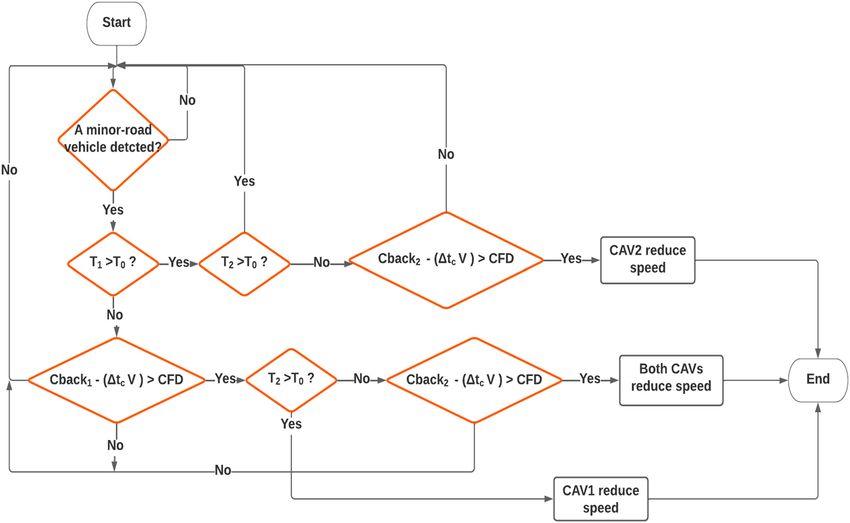
274 Fayez Alanazi and Ping Yi
In many applications, the critical gap is measured by the (V2V) and Vehicle to Infrastructure (V2I) communication
smallest gap drivers accept on intersections [8]. technologies, intelligent vehicles could make driving
At major–minor intersections, traffic control for vehi- informed decisions based on multi-source data, such as
cles on the major road generally prioritizes the minor the speed/location of surrounding vehicles and the signal
road. Driver behavior from the minor road vehicle is plans of surrounding intersections. The headway distribu-
highly affected by the number of available gaps on the tion of vehicles streaming on a mainline road towards an
major road. With light traffic on the major road, larger intersection can significantly affect the number of usable
gaps may be found in the traffic stream; on the other gaps that a minor road enters the intersection.
hand, heavy traffic on the major road is more likely to This research aims to utilize CAVs to help generate
have smaller and less safe gaps for the minor road drivers additional adequate gaps for the minor road vehicles to
to choose from. The vehicle delay for the minor road enter the intersection without interrupting the mainline
vehicle influences the critical gap selection. A longer traffic flow. The methodology works when vehicle arrivals
waiting time experienced by the driver while waiting on the main road permit the implementation of the con-
can result in losing patience to accept a shorter critical trol strategy to improve intersection efficiency in mixed
gap [9]. traffic conditions. This study consists of three main con-
Moreover, additional factors may also influence the tributions, which are: formulating a probability model to
gap selection behavior of the driver, including age group, identify the headways that are less than the critical
time of the day, and trip purpose, but the most observed headway that can be used by minor road vehicles when
factors are the presence of a queue behind the driver, the CAVs reduce speed. Additionally, this research devel-
number of gaps rejected, as well as the wait time. The oped a framework that guides CAVs in creating gaps at
presence of a queue behind the driver is likely to make such intersections while considering safety and efficiency
the driver feel pressured and thus, accept a smaller gap; under mixed traffic conditions. The framework was simu-
when more gaps are rejected with an extended waiting lated in a microscopic environment to validate and eval-
time, the minor road drivers may become impatient and uate the efficiency and safety of the intersection before
choose to accept smaller gaps [10,11]. and after the method. A field investigation was conducted
Connected and automated vehicles (CAVs) use advanced at two different locations to study the feasibility of the
wireless technologies like Cellular Vehicle-to-Everything proposed algorithm.
(C-V2X) or Dedicated Short-Range Communication (DSRC).
These wireless technologies would create a link between the
vehicle and the network or among vehicles to share informa-
tion such as speed [12], location, traffic control, etc. Such 2 Literature review
data communication capabilities and the supporting infra-
structure may help improve traffic operation and reduce CAV technologies offer potentially transformative traffic
traffic flow interruption, thereby enhancing safety, fuel con- impacts, including significant mobility, safety, and envir-
sumption, and emission [13,14]. onmental benefits. Numerous algorithms have been devel-
When combined with the wireless communication oped to improve intersection throughput, and most of
systems, the automated driving and data processing tech- them used simulation to evaluate the proposed methods
nology empower CAVs to be a potential solution to many [1]. Simulation assumptions limit the validity of evaluation
field problems that are difficult to solve or require exces- results, and the lack of conducting field experiments in
sive resources to deal with by using the traditional engi- real traffic conditions exacerbates this problem of inaccu-
neering method. It is also well understood that, before racy, leading to improper model evaluation. This problem
CAVs become dominant, frequently used technology, a has resulted in a wide range of differences in effectiveness
mixed form of vehicles, and human-driven vehicles (HDVs) among studies examining the same CAV applications.
along with CAVs, will be driving simultaneously on the road, Since it is too early to achieve high penetration of CAVs
so it is important to investigate CAVs at intersections and AVs on roads, it is practical and essential to investi-
considering mixed traffic condition with different CAVs’ gate the mixed flow of HDVs and intelligent vehicles at
penetration. currently used intersections [15,16].
In the past decades, emerging technologies that could Many CAV application studies on unsignalized or
assist or automatically control the driving process of intel- signalized intersections have been reported, and most
ligent vehicles have drawn great interest from researchers of them are conducted under the assumption of a 100%
and engineers. With the development of Vehicle to Vehicle CAV environment to explore potential benefits of the
Control logic algorithm for mixed traffic: A comprehensive evaluation 275
CAVs; only a few studies have focused on unsignalized The purpose behind the development of AIM is to
intersections or minor roads with semi-actuated signal ensure that all the vehicles follow the controller by com-
control in mixed traffic conditions [1]. Zhong et al. studied promising the connected automated or autonomous vehicle
a priority unsignalized intersection management to ensure (AVs/CAVs). However, limited studies have focused on the
vehicle crossing, while considering the efficiency and interaction of AIM with human vehicles (HVs) that are
safety of both the approaches [17]. Similarly, a gap-based either partially or completely un-equipped with V2V and
eco-driving speed control algorithm for unsignalized inter- V2I communication facilities, along with the ones with no
sections was studied [18] by considering the realistic traffic autonomous driving module [18]. Most of the researchers
conditions. The proposed algorithm incorporates gaps, studying the interaction use traffic lights as the medium of
initial speed, and vehicular position as control variables communication with HVs, while others only consider auto-
while optimizing the acceleration/deceleration to cross the mated vehicles and autonomous vehicles without consid-
intersection. Although the proposed method was found to ering the mixed traffic.
improve efficiency while considering safety, the study con- The application of CAV on unsignalized intersections
siders only fully automated vehicles at the intersection. has been explored in many studies. Among these studies,
Many studies have presented various distributions to a major proportion of this research is conducted on the
represent the headways for traffic with only conventional assumption of a 100% CAV environment to explore the
vehicles, but not many exist for pure CAVs or a mixed benefits of the CAVs. However, only a few studies focus
traffic stream. For single-lane traffic, there are various on the unsignalized intersections in mixed traffic condi-
sequence combinations of conventional vehicles and CAVs, tions [31]. Chen et al. [32], in their study, explored the
such as conventional vehicles following conventional vehi- prioritization of unsignalized intersection management
cles, conventional vehicles following CAVs, CAVs following to ensure vehicle crossing along with considering the
CAVs, and CAVs following conventional vehicles. With an safety and efficiency of the approaches. It is suggested
intention to develop an algorithm that can help minor road that vehicles on the major road enjoy priority while also
vehicles to have more usable gaps to enter the intersection creating gaps for those on the minor road. In this regard,
based on the technology of CAVs, this article is focused on a gap-based approach equipped with an eco-driving
the probability distribution of the headways to counter for speed control algorithm has been studied for unsigna-
the number of possible headways where CAVs can create the lized intersections to take into consideration the realistic
usable gaps for the minor road vehicles. traffic conditions. The purpose of the algorithm is to
Autonomous Intersection Management, or AIMS, was include information related to gaps, vehicle position,
first put forth in the works of Dresner and Stone, which and initial speed as control variables, while suggesting
was followed by several researchers in similar concepts, ways to optimize and develop acceleration and decelera-
most of which used the First-come, first-serve (FCFS) tion profiles and it helps the vehicle at the stop line.
model [19]. Several methods have been used to develop Though the study incorporated only fully automated
AIMS; including mixed-integer linear programming [20], vehicles at the intersection, the study has been found to
linear programming [21], and mixed-integer non-linear have positively improved the efficiency of AIM while fac-
programming [22]. The purpose of formulating AIMS in toring in the element of safety.
different models was to ensure optimization [23] while All the above studies have treated the traffic coming
also serving as a control framework [24]. Likewise, there to the intersection at an equal level of importance. More
have been models that focus on the issues related to studies are needed at a major–minor intersection with
dynamic optimization [25] and models of predictive con- priority set for the major road under mixed traffic condi-
trol framework [26] of AIMS. tions. A few studies conducted a feasibility study to test the
Various AIM models illustrated different findings. capability of the control algorithm in real traffic scenarios.
Some models discussed the vehicle arrival time at the This research aims to utilize CAVs to help generate addi-
departing time or conflicting points alongside the calcu- tional adequate gaps for the minor road vehicles to enter
lation of intersection exit time [27]. While on the other the intersection without interrupting the mainline traffic
hand, some models focused on the vehicle number which flow. The methodology works when vehicle arrivals on
was allowed to move [22]. Nevertheless, all these models the main road permit the implementation of the control
are intended to maximize the overall throughput of AIM strategy to improve intersection efficiency in mixed traffic
[28] while also limiting the travel period [29] as well as conditions.
reducing the fuel consumption [30] to diminish the poten- The rest of the article is organized as follows: First,
tial threats, if any [24]. the number of headways that CAVs can create under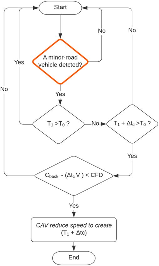
276 Fayez Alanazi and Ping Yi
mixed traffic conditions using the expected probability Poisson distribution describes the probability of having
headway distribution is calculated. Then, the framework a certain number of vehicles arriving at a given time
that guides CAVs in creating gaps is proposed, including interval, and it is calculated as follow:
the formulation, communication, and simulation of the e−m m x
proposed method in two different cases. Next the simula- p (X = x ) = , 0 ≤ x ≤ ∞, (1)
x!
tion results are conducted to validate the effectiveness of
the proposed method. Also, a field test is then conducted where m is the average arrival rate, and x is the number of
to validate the proposed algorithm in real traffic condi- vehicles. Since m is dependent on the duration of t, it can
tions, and finally, the conclusion of this work and some be written as vt , where v is the number of vehicles
future works to improve this study are presented. expressed in a unit time.
Since the probability of having no vehicles arriving
during time t represents the probability of having the
next headway at t or longer, the headway distribution
3 Methodology for those at least the size of the critical headway, tcr , for
merging into the main road can be estimated by modi-
The methodology in this article is presented in sections, fying equation (1). For vehicles to merge into the major
and consists of three main sections: (i) developing a road from a minor approach, headways at or larger than
headway distribution of the main road-stream to predict tcr are required, which and all headways, can be obtained
the possibility of gaps that CAVs can help to create; (ii) through an adjusted probability density function, as:
developing a framework (control logic) that guides CAVs ∞
to create additional gaps on the mainline for the minor P¯0(t ≥ tcr ) = ∫ 2 πv 2
e−v (tcr)dt , (2)
road vehicles to enter the intersection safely; (iii) evalu- tcr
ating the proposed algorithm by an experiment of case
where tcr represents the critical headway in seconds, and
studies for two types of intersections.
v is the traffic volume in veh/s.
Solving equation (2) using the Gaussian error func-
tion method, the cumulative probability that headways in
the mainline traffic are greater than or equal to the critical
3.1 Gap acceptance of unsignalized
headway tcr would be:
intersections
P¯0 = 1 − erf( v tcr ) . (3)
Gap acceptance at an intersection of a major road and a Vehicles’ arrival at a major–minor road intersection
minor road depends on the choice of the minor road vehicle on the major road is affected by traffic volume and influ-
to accept an available headway between approaching vehi- enced by the local conditions, with interarrival times not
cles. However, the amount of delay by the minor road less than the minimum headway, tmin , which is the
vehicle before merging into the major roads depends on shortest car-following time interval or spacing expressed
the frequency and distribution of headways equal to or in time. The expected cumulative probability of all head-
greater than the critical headway selected as the minimum ways less than the minimum headway is determined as
acceptable headway to enter. At a major–minor intersection follow:
most seen in suburban areas, the upstream signals often do
tmin
not affect vehicle arrivals at intersections. Numerous studies
have found that such vehicle arrivals follow the Poisson Pmin(t ≥ tmin) = ∫ 2 πv 2
e−v (tmin )dt , (4)
distribution in light to medium traffic flows [33,34]. 0
where tmin is the minimum headway in seconds.
Solving equation (4) to get:
3.1.1 Headway distribution on major road
P¯min = erf( v tcr ) . (5)
Headway is the time interval between two successive The critical headway is larger than the minimum
vehicle arrivals at a point. A waiting vehicle on the minor headway. The purpose of this research is to help create
road approach will merge into the major road only if a additional gap time between arriving vehicles on the
proper headway t is available on the major road. The major road by using CAVs that reduce the approaching
Control logic algorithm for mixed traffic: A comprehensive evaluation 277
speed to the preceding vehicles so that some of the gaps 120
less than the critical gap may be extended and become
100
usable. For safety concerns, the slowdown by a CAV is
Number of Gaps
limited to the maximum allowable reduction in speed in 80
case of small vehicle spacing behind the CAV. Based on 60
field data in this research, the size of the additional gaps 40
that CAVs can create is in a certain range, definable at the
20
specific testing sites with sight distance and data com-
0
munication limits. More discussion on the related aspects 0 200 400 600 800 1000 1200 1400 1600
is given in the later sections of the article. Major road Volume (veh/hr)
For simplicity in developing the prototype model and
10% 20% 30% 50% 70%
control logic, we focused our discussion on the single-
lane situation where the entering vehicle from the minor
Figure 1: Number of usable gaps CAVs may possibly help create for
road only needs to watch the traffic on one lane from each
right turns.
direction. To help estimate the scope of application of the
proposed study, the probability that CAVs can create
additional gap times in the major road traffic stream, or P¯CAV(L) = P¯CAV(E)⁎ P¯CAV(W), (8)
P̄CAV , is estimated as the difference between the head-
ways less than the critical headway and those greater where P̄CAV(E) is the probability of headways that an east-
than the minimum headway: bound CAV can help create and P̄CAV(W) is that for the
westbound CAV. The number of headways that CAVs
P¯CAV = (1 − P¯0) − P¯min. (6)
can utilize to create additional usable gaps for the minor
Since CAVs are mixed with regular vehicles, the total road vehicles turning left is shown in Figure 2, at different
number of additional headways, Ncav , that CAVs can pos- levels of CAV penetration and major road volume.
sibly create depends on the number of CAVs, qcav , on the Figure 2 shows that, since the left-turn vehicles would
major road and can be determined as: need to find a safe gap in both directions on the major
road, the probability of finding such a gap is less than
Ncav = (P¯CAV )⁎ qcav . (7)
vehicles turning right. Similarly, the number of gaps crea-
The opportunities for CAVs to help create additional table by CAVs for the minor road left turns increases
usable gaps for the minor road vehicles are influenced with the increase in the major road volume and the
by the traffic volume and market penetration rate of CAVs CAVs penetration, and as the major road volume continues
on the major road. Using equations (2)–(7), Figure 1 to increase, the number of such gaps decreases as more
shows how Ncav for right-turning vehicles on the minor vehicles on the major road result in smaller gaps.
road changes at different major road volumes and CAV
penetrations.
The results show that Ncav increases with the increase
in CAVs’ penetration and the major road volume. However,
when the major road volume increases, the number of gaps 40
decreases. This is understandable because with the increase 35
in the major road volume, the headway between two suc- 30
Number of Gaps
25
cessive vehicles becomes smaller, making it more difficult to
20
create a headway greater than the critical gap.
15
Equations (2)–(7) have considered only one direction
10
of the mainline traffic, so they can only be applied to the 5
right-turning vehicles from the minor road. More com- 0
0 200 400 600 800 1000 1200 1400 1600
monly, a two-way traffic condition should be considered
Major road volume (veh/hr)
since there are left-turn vehicles from the minor road
as well. Therefore, the number of gaps that can be created 10% 20% 30% 50% 70%
in both directions for the vehicles turning left relies on
the conditional probability in the desired gap range as Figure 2: Number of gaps CAVs can possibly help create for left
follows: turns.
278 Fayez Alanazi and Ping Yi
3.2 Control logic 3. CAVs can detect the leading and following vehicles
and determine the spacings at different speeds of
It has been shown that CAVs can help create additional those vehicles.
usable gaps for the minor road vehicles to enter the
major road. This section discusses the development of
3.2.2 The front gap
an operational algorithm for generating such gaps and
the supporting vehicle control strategies. The objective is
The proposed control system works in a mixed traffic
to develop a systematic framework and implementation
environment since it considers both CAVs and HVs.
plan that uses CAVs for gap creation so that the applica-
When a CAV is within the communication range with
tion can be analyzed in simulation and its feasibility
the RSU, and a vehicle is detected in the minor street,
tested in the field. The control algorithm considers safety
the CAV detects the vehicle ahead of it and calculates
as the priority, and it intends to minimize interruptions
whether the front gap when it moves to the intersection
to the mainline traffic flow due to vehicles from the
is greater than the critical gap. If the gap is not more than
minor road.
the critical gap, as explained in the previous section, the
CAV will decide how much speed reduction is needed to
help maintain a distance beyond the established critical
3.2.1 Intersection layout
gap if other conditions permit.
In the scenario shown in Figure 4, the CAV is fol-
T-intersections are commonly seen in areas when a minor
lowing an HV and separated by an existing gap time,
road joins a major road, where vehicles from the minor
T1, which is measured as:
road merge into the mainline traffic stream by making a
left or right turn. The minor road approach is controlled LAV L
T1 = − HV , (9)
by either an actuated signal or a stop sign where the v v
major road traffic is given the right of way most of the where v is the approaching speed in ft/s, LAV is the dis-
time, as shown in Figure 3. CAVs are operated only on tance of the CAV from the intersection, and LOV is the
the major road, and the vehicles on the minor road are all distance of the HV to the intersection. Since the distances
HVs; the case of CAVs on the minor road is not considered are measured near the intersection, speed variation before
here since it is easier for communication and vehicle reaching the intersection is not considered.
control. The minor road vehicle looking for a safe gap to enter
The main assumptions of the modeling method are as the intersection requires a gap equal to or greater than
follows: the critical gap, T0. For a minor street vehicle to enter the
1. The intersection has been instrumented with a road- intersection safely, T1 must be greater than T0. In the
side unit (RSU) for data communication with all CAVs. scenario where T1 is less than T0, and approaching CAV
2. The geometric and environmental conditions do not will be looked at for possible speed reduction to add some
hinder the decision-making and operation of the minor extra gap time, Δtc , in the front vehicle, as shown in
road vehicles. Figure 5:
Major Major
Street Street
RSU
CAV
HV
Minor
Street
Figure 3: Layout of the intersection studied.
Control logic algorithm for mixed traffic: A comprehensive evaluation 279
Major Major
Street Street
RSU
T1
CAV
L
HV
Minor
Street
Figure 4: Front gap between CAV and the leading vehicle, T1.
LAV L and
Δtc = − AV , (10)
vc v
LAV L
− HV ≥ T0. (15)
where vc is the speed of CAV after reduction. βv v
The extra gap time added to T1 must have a combined
The time delay for communication between the CAV
value greater than T0. As a result, the following equation
and the RSU through DSRC or C-V2X can be neglected
is obtained:
compared with the time needed for vehicle speed adjust-
LAV L ment [33]. However, the time for the CAV to reach the
− HV + Δtc ≥ T0. (11)
v v desired speed during gap creation, or the transition time,
Substituting Δtc using equation (10), then: Δttrans , must be taken into consideration. This transition
time is measured from when CAV receives the speed con-
LAV L L L
− HV + AV − AV ≥ T0. (12) trol instruction till it reaches the required speed. This extra
v v vc v
time must be compensated during gap creation; thus,
This results in: equation (15) is modified as
LAV L LAV L
− HV ≥ T0. (13) − HV ≥ T0 + Δttrans. (16)
vc v βv v
If the level of speed reduction by the CAV is denoted The equation for the gap that CAV creates is then
as β , then calculated at a specific reduction in speed β to achieve
vc = βv, (14) the gap needed for the minor road vehicle to enter the
intersection, as follows:
Major
Major
Street
Street
RSU
∆tc
LAV before reducon
CAV
HV
Minor
Street
Figure 5: Extra time added to increase the gap time, Δtc .
280 Fayez Alanazi and Ping Yi
LAV because it has been widely used by the consulting industry,
− LHV − (v × Δttrans) ≥ (v × T0) . (17)
β transportation authorities, and universities [14].
Two types of intersection control are considered to
demonstrate how the proposed algorithm works, including
3.2.3 The back gap a stop sign control and a semi-actuated signal control at a
T-intersection. The three-legged intersection may include
Equations (9)–(17) have considered only the case of a one or more lanes on the major road, and only one lane on
vehicle ahead of the CAV. However, there may also be the minor road. Vehicles from the minor road approach
a vehicle behind the CAV at the same time. This back and merge into the major road from a designed left-turn or
gap, Cback , as well as the speed of the following vehicle right-turn bay. The detector placed on the minor road-
imposes a major constraint on the potential speed reduc- stream is connected with RSU to obtain the information
tion by the CAV. As shown in Figure 5, before CAV when a minor road is detected and needed a gap.
reduces speed to expand the front gap, it checks the spa-
cing and speed of the following vehicle and calculates to
ensure that the following vehicle would not be severely 3.3.1 Unsignalized intersection
affected by the speed reduction of the CAV. For safety, the
back gap should be at least greater than the safe car- In this case, as shown in Figure 3, the major road traffic
following distance (CFD) for consideration of reducing has the right of way, and the minor road vehicle has to
the CAV’s speed, that is wait at the stop sign before merging. The minor road
Cback ≥ CFD, (18) vehicle will enter only if there is a gap equal to or greater
than the critical gap. For a vehicle waiting to join the
where major road by a right turn, the control system has two
vo2 − vf2 options to take, as explained below:
CFD = vo tr + , (19)
30( f ± G ) Option 1: Do nothing: This scenario is when a CAV is
within the range of communication but do not help create
where Vo refers to the initial speed of the following vehicle a usable gap due to one or more of the following possible
(mph); vf represents the post-reduction speed of CAV conditions:
(mph); tr is the reaction time (s); f is the friction coeffi- 1. The front gap time of the CAV from the leading HV is
cient, and G is the grade level of the street. greater than the critical gap, so there is no need for gap
An additional term is further used to ease the impact extension, or:
of the back gap reduction. As shown in Figure 6, a
threshold distance (clearance) between the CAV and the T1 ≥ T0
following vehicle is considered at different speed levels. 2. The front gap time of the CAV is less than the critical
This clearance distance between the two vehicles can be gap, but the CAV is not able to help because the CAV is
expressed using a time factor, Δtc , which can be added to too close to the leading HV and not enough time can
equation (18) to get: be saved by slowing down, that is:
Cback − (Δtc vf ) ≥ CFD. (20) T1 + Δtc < T0
The case of CAV with a front vehicle and a back 3. The back gap behind the CAV from the following HV is
vehicle represents a complex situation; the safety condi- less than the safe distance required. This scenario is
tions established also apply if a CAV is following another when the following HV is very close to the CAV, and it
CAV. In this case, the first calculation will start with the is unsafe for the CAV to reduce speed, or:
front gap to ensure a gap can be created before checking
Cback − (Δtc V ) < CFD
the safety behind the CAV reducing speed.
Option 2: Reduce speed: This scenario is when a CAV
can reduce speed to help create a usable gap for the
3.3 Experiential evaluation minor road vehicle after satisfying both of the following
conditions:
To prove the concept and estimate the potential effective- 1. The front gap time is less than the critical gap and
ness of the proposed control method, a simulation was CAV, and a CAV can help extend the gap not less
performed on the VISSIM platform. VISSIM is chosen than the critical gap by reducing speed, that is:
Control logic algorithm for mixed traffic: A comprehensive evaluation 281
T1 < T0
RSU
CAV
HV
Minor
Street
Figure 6: The back gap and front gap after speed reduction.
T1 + Δtc ≥ T0 Our research intends to improve the operation of this
2. The back gap of the CAV from the following HV is type of intersection in a similar way to the unsignalized
greater than the safe distance:
Cback − (Δtc V ) ≥ CFD
The control logic of the above process is shown in
Figure 7.
The above discussion has focused only on one direc-
tion of traffic on the major road when the minor road
vehicles make a right turn. However, for a minor road
vehicle to turn left, safety considerations must be given
to both directions of traffic on the major road because of
the increased potential conflicts. Figure 8 shows a minor
road vehicle waiting for a gap to turn left and join the
mainline traffic.
In this case, the system will check if the condition,
Ti < T0, exists and the CAV can slow down to create
the needed gap value of Δtc in each direction, so that
Ti + Δtc ≥ T0. In addition, the algorithm will check if
the back gap conditions discussed above can be satisfied.
If either the front or back gap in any direction does not
meet the requirements, the algorithm will select Option 1
(do nothing). The added control logic is shown in Figure 9.
3.3.2 Semi-actuated signal control
Another application of the proposed control strategy is at
a T-intersection under semi-actuated signal control. In
most such intersections today, green light interruptions
to the mainline traffic are used when an individual vehicle
arrives and is detected at the minor road approach. Since
semi-actuated control generally does not optimize inter-
section performance, this often causes multi-vehicle stop-
pings and significant delays to the mainline vehicles even Figure 7: Control logic for a right-turning vehicle in mixed
though it could serve just one vehicle on the minor road. traffic flow.282 Fayez Alanazi and Ping Yi
T2 C Back 2
C Back 1 T1
RSU
RSU
CAV
HV
Minor
Street
Figure 8: Road entry through a left turn.
intersections. Taking advantage of the modern detection “holds off” the detector status change information by
and signal control technologies, the control method pro- employing the detection delay function, while at the
poses to extend the green time on the major road to allow same time, the gap searching and creation procedure
gap creation by CAVs without switching the green time using CAVs is executed. The minor road will be able to
to the minor road. Specifically, for application of the join the mainline flow if a usable gap is successfully cre-
system, the major road signal is set in the green-rest ated; otherwise, the detector status change is reported,
(GR) mode while a flashing red (FR) is used for the minor and the “hold” is released to allow the green signal switch
road, where the minor road vehicle can still merge into to the minor road, avoiding excessive delay to the minor
the mainline flow if a proper gap is available. The FR road waiting for the vehicle.
operation is functionally similar to a stop sign, but its As the modified algorithm temporarily operates a FR
advantage lies in the ability of the signal system to change for the minor road when a vehicle is waiting to enter the
operation according to real-time detection. When a vehicle intersection, the CAVs in the mainline flow can execute
is detected waiting at the minor road approach, the detector the gap creation. If the minor approach vehicle cannot
Figure 9: Control logic for a left-turn vehicle in mixed traffic flow.Control logic algorithm for mixed traffic: A comprehensive evaluation 283
find a proper gap to use if there are no CAVs in the main-
line traffic, the traffic signal resumes its semi-actuated
operation. The control logic for the algorithm to work at
a semi-actuated signal is shown in Figure 10. The effec-
tiveness of the control algorithm can be measured by
comparing how often the mainline signal is interrupted
with and without the help of CAVs.
3.3.3 Simulation results
Several key parameters are determined before the simu-
lation study as shown below. While the critical gap
values recommended by HCM may be used for general
traffic conditions, it is understood that a more accurate
estimation of the critical gap is from field observations at
a specific location, especially if other relevant model
parameters are also developed from the local data. This
research has conducted a field study and analyzed gap
selection conditions to obtain the critical gap for the use
in the simulation. Similarly, the clearance distance (Δtc )
is obtained by looking at the minimum clearance between
stopped vehicles and the transition time (Δttrans ) is calcu-
lated by applying the normal deceleration rate to the speed
difference. Additionally, the gap utilization factor is
developed by finding the number of gaps accepted by
the minor road vehicles out of the total number of usable
gaps based on field observations. Finally, the level of
speed reduction (β) is determined by tracking the speed
changes when individual vehicles from the major road
reduce speed to turn into the minor road at the selected
field location.
Figure 10: Control logic for semi-actuated signal control.
Due to the stochastic nature of traffic arrivals, a
minimum of ten simulation runs were performed for
each volume and CAV rate combination with different 3.3.3.1 Unsignalized intersection
random speed numbers to ensure that the values reported
incorporated the stochastic changes in the traffic flow. The stopped delay occurs when a vehicle is waiting for a
The test plan includes comparisons to evaluate intersec- safe gap at the minor road-stream. The average stopped
tion performance before and after implementing the CAV delay is shown in Figure 11, where three different CAV
algorithm to create gaps. Thus, two types of vehicle com- percentages are presented as 30, 50, and 70%. Figure 11
positions are specified. The first is when there are no corresponds to the minor road volumes as 100, 150, 200,
CAVs on the major road, which is the benchmark for and 250 veh/h, respectively.
comparison, and the second includes a mixed traffic con- As shown in Figure 8, when the CAV rate to the total
dition with CAVs and HVs. volume of vehicles on the major road increases, the
The performance results of the proposed algorithm of stopped delay on the minor road approach decreases to
both cases (unsignalized and semi-actuated) are pre- a certain level. This is primarily because the increase in
sented and analyzed next. Different traffic demand levels CAVs can help create more safe gaps, resulting in less
are considered on the major and minor roads, along with waiting time and improved stopped delay on the minor
different penetration rates of CAVs on the major road. The road compared with the no CAV situation on the major
measures of effectiveness (MOEs) are used to evaluate the road. However, once the major road volume reaches a
proposed method, including delay and capacity. high level, the improvements start to decrease because284 Fayez Alanazi and Ping Yi
more vehicles on the major road result in shorter head- added delay to the major approach reaches 11% at a
ways between vehicles, and the smaller headways reduce higher level of traffic on the major and minor roads, the
the possibility for CAVs to create safe gaps for the minor improvement in the minor road approaches increases to
road vehicles. 62%. Thus, the proposed method at unsignalized inter-
Gap creation by CAVs may cause additional delays on sections, in general, helps the minor-road approach vehi-
the major road. This impact is also studied by obtaining cles without seriously affecting the major road operation.
the average delay on the major road approaches before
and after the proposed method, as:
Change in averge delay = Delay with CAVs 3.3.3.2 Semi-actuated signal
(21)
− Delay without CAVs.
During simulation, a minimum green and a maximum
Table 1 shows a comparison between the delay added green time are used for the semi-actuated signal on the
to the major road and the reduced delay on the minor major road. The traffic flow is classified into three volume
road. The results show that the delay caused to the major levels: low, medium, and high, for which the corre-
road at low minor road volumes is very low while the sponding maximum green time for the major road is 50,
reduction in the minor approach is 23–30%. When the 60, and 70 s and the minimum green is 20, 25, and 30 s,
Figure 11: Improvement in delay for the minor road vehicles.Control logic algorithm for mixed traffic: A comprehensive evaluation 285
Table 1: Comparison of delays due to gap creation by CAVs respectively. However, if no calls are placed by the minor
road vehicle, the major road will stay on GR. On the other
Minor Major CAV (%) Delay Improvements in hand, for the minor road, the “holding” time (before
road road added delay (minor reporting the detector status change) for low, medium,
volume volume (major road) (%)
and high major road volumes is set as 15, 20, and 25 s,
(vph) (vph) road) (%)
respectively.
100 600 50 1 23 The signal interruptions are counted when the minor
1,000 50 2 30
road vehicles are not able to use a safe gap in the mixed
150 800 30 3 15
1,200 30 6 40
flow. The signal switches stop the major road traffic and
200 600 70 4 23 serve the minor road vehicles. Figures 12 and 13 illustrate
1,000 70 11 62 the number of interrupted signals at different CAVs’ pene-
250 800 30 6 22 tration rates with different allowable maximum waiting
1,200 50 20 25 times on the minor approach.
Figure 12: Signal interruptions on the mainline at 150 veh/h on the minor road.286 Fayez Alanazi and Ping Yi
Figure 13: Signal interruptions on the mainline at 250 veh/h on the minor road.
It can be found that at a low volume on the major when the minor road volume is 100, 150, 200, and
road, the number of mainline interruptions is less 250 veh/h, respectively.
than when the major road volume gets higher. Also, an It can be seen that at all levels of minor road volume,
increase in the minor road volume leads to more signal the control delay increases with the increase in the major
interruptions. Further, with the increase in the CAV rate in road volume if no CAVs are used to help create usable
the mainline traffic, the number of signal interruptions gaps. However, when different levels of CAV penetrations
decreases, since more CAVs increase the probability of are introduced, the control delay decreases as more CAVs
creating safe gaps for the minor road to enter the main become available. The results in Figure 13 also show that
road. This helps improve the waiting time at the minor with the increase in the minor road volume, the control
road approach and thus reduces the need to switch the delay increase due to the increase in calls from the minor
signal. road detection; however, at a given minor road volume,
The improvement in the intersection operation is the CAVs can help reduce the signal interruptions.
evaluated by measuring the control delay, a primary Since CAVs help to create additional usable gaps on
LOS indicator in the Highway Capacity Manual (HCM). the mainline traffic stream, the number of minor road
Figure 14 presents the control delay at different levels vehicles that need signal accommodations would decrease,
of traffic volume on the major and minor roads along leading to a potential increase in intersection capacity,
with different CAV rates. Figure 14 shows the results referred to as surplus capacity in this articl. This surplusControl logic algorithm for mixed traffic: A comprehensive evaluation 287
capacity is analyzed by subtracting the number of gaps service after other vehicles have taken advantage of the
successfully created by CAVs and taken by the minor road created gaps to merge into the main road.
vehicles, from the total demand on the minor road that
would otherwise have required the signal service. Figure 14
shows the surplus capacity as a percentage increase to the
intersection capacity with different traffic volumes on the 4 Field test
major and minor roads.
Figure 15 presents the surplus capacity at different This field test aims to study the feasibility of the control logic
traffic volumes on the major and minor roads. The results implementation in real traffic conditions. The investigation
show the surplus capacity increases as more CAVs are evaluates the execution of the framework in this research
available in the mainline traffic stream. However, the under the scenarios explained in the above section.
capacity increase starts to decline when the mainline
traffic volume continues to grow, indicating the difficul-
ties for CAVs to find opportunities to create useable gaps. 4.1 Site selection
Figure 15 also shows that surplus capacity becomes much
lower at a high minor road volume, reflecting that the The selection of the test site to conduct the experiments is
remaining vehicles on the minor road still need signal based on the following criteria:
Figure 14: Improvement in control delay at different levels of CAV penetration.288 Fayez Alanazi and Ping Yi
Figure 15: Surplus capacity at different levels of traffic volume.
1. Good access to the site and easiness to markup refer-
Observer ence points on the roadside.
2. Reasonable traffic volumes on both major and minor
roads, so that good quality data for normal traffic con-
CAV
Maintain Speed Speed Reducon
ditions can be collected.
3. Good sight distances in both directions to ensure that
Decision
Minor
the poor geometric conditions do not impose compli-
Street
cations to the test.
4. Suitable safe spots to station the test vehicles on the
major road without being too close to the intersection.
After visiting several T-intersections, two sites have
been selected for the field test. The intersection of Wilbeth
Road and Inman Street (minor road) in Akron, OH is sig-
nalized with a FR on Inman and a flashing yellow on
Wilbeth as the default control plan. On the other hand,
Figure 16: Setup for field test. the intersection of Fishcreek Road and Sowul BoulevardControl logic algorithm for mixed traffic: A comprehensive evaluation 289
100 100
Cumulave % of No. of gaps
Cumulave % of No. of gaps
90 90
80
accepted or rejected
accepted or rejected
80
70 70
60 60
50 50
40 40
30 30
20 20
10 10
0 0
0 1 2 3 4 5 6 7 8 9 10 11 12 0 1 2 3 4 5 6 7 8 9 10 11 12
Gap Size (sec) - Stow (mostly le turns) Gap me (sec) - Akron (mostly right turns)
Rejected Gaps Accepted Gaps Rejected Gaps Accepted Gaps
Figure 17: Critical gap estimate using Raff’s method.
(minor) in Stow, OH is controlled by a stop sign on Sowul road vehicle accepted the expanded gap to enter the main
Boulevard. road, it would be counted as an accepted gap. On the
other hand, if the minor-road driver did not select the
gap, it would be considered a rejected gap.
4.2 Experiment design and execution To help verify the success rate in the gap created by our
test vehicles, two methods were used to collect field data
Since the CAV technologies for applications in this study during the experiment, a manual data sheet and a high-
are still being developed, we used our own vehicle as a quality video recorded using a Mini-DVI drone for data
CAV in each direction of the main road. Communications checking along with the manually entered data points. The
within the system were realized by voice commands over tests were conducted at different times of the day and dif-
cellphones between the observer at the intersection and ferent days of the week to increase the generality of the data.
the test vehicles. Each test usually takes 1–2 h from setting up the site to fin-
Each test vehicle included the driver, front gap watcher, ishing the data collection, as the video drone records the data
and back gap watcher. The front gap watcher estimates the simultaneously. After each field test, data from the video
distance between the test vehicle and the preceding vehicle were extracted manually and compared with the manual
using temporary roadside marks. This person uses pre- sheets at the Transportation Lab of The University of Akron.
established reference points from spacing requirements to
determine if the test vehicle is too close to the front vehicle
(cannot create a long enough gap) or if the vehicle has 4.3 Critical gap
reached the speed reduction zone to carry out the procedure
(shown by the red line in Figure 16). Before the test vehicles were deployed, gap acceptance
The back gap watcher estimates the distance between data without the presence of CAVs were collected at the
the test vehicle and the following vehicle also by using intersection to help establish the critical gap and other
the roadside marks. The observer at the intersection com-
municates with the driver regarding conditions at the Table 2: Data point collected on the field
intersection and issues a “NO” command if an unusual
situation arises, such as a pedestrian or bicycle crossing Location Minor road vehicle Driver decision Total
the road. When a minor road vehicle is approaching the movement
intersection, the observer at the intersection informs the
Right Left Accept Reject
test vehicles waiting upstream of the intersection to enter
the major road from each direction. If the conditions Akron 43 23 42 24 66
Stow 8 47 34 21 55
reported all support a “YES” command, the test vehicles
Total 51 70 76 45 121
slow down to generate additional gap time. If the minor-290 Fayez Alanazi and Ping Yi
local traffic parameters that were used in the simulation may reduce delay while waiting to enter the main road
study described before. For example, the minor road vehi- and the interruptions to the continuous mainline flow. The
cle’s waiting time was also determined from the field data, article considers a mixed traffic environment, in which both
which was used to suggest the detector status “holding” CAVs and HVs share the same right-of-way. A probability
time for the semi-actuated signal control in the simulation. function was developed to assess the number of usable gaps
The critical gap was estimated by following Raff’s that CAVs may help create at different volume levels and CAV
method [17]. The data includes a total of 512 gap selections, rates on the major road. Since the right turn movements from
including 197 from the Akron site and 315 from the Stow the minor road conflict with only one direction of the mainline
site. An example of the cumulative accepted and rejected traffic, the number of possible gaps to be created is greater
gap curves is illustrated in Figure 17, where it can be seen than the left-turn movements, since the latter conflicts with the
that the critical gap at the Akron location is approximately mainline traffic in both directions, with a reduction in the
6.5 s, whereas at the Stow location is nearly 7.0 s. possibility of simultaneous assistance by CAVs.
A simulation study was performed on the VISSIM
platform involving two types of intersection control to
4.4 Results investigate the effectiveness of the proposed algorithm.
The simulation results showed that the proposed method
In the entire field-testing effort, a total of 121 successfully might effectively reduce delay for the minor road vehicles
executed cases have been recorded, roughly 60 for each without causing a significant increase in delay on the
intersection. As shown in Table 2, the results show that at major road at unsignalized intersections. When a semi-
the Akron test site, the acceptance rate by the minor road actuated signal control is considered, the results show
vehicles to the gaps created is close to 64%, indicating that that the creation of additional gap times by CAVs would
most drivers are willing to accept the gaps created by the substantially reduce the number of interruptions to the
test vehicles. On the other hand, gaps that were rejected by mainline traffic flow and reduce the intersection control
the minor road drivers are 36%. This indicates that many delay. Field testing was also conducted, and the objective
drivers are very cautious regarding roadway entry from a is to investigate the feasibility of implementing the pro-
minor road. The underlined numbers in parentheses repre- posed method in field conditions. This proof-of-concept
sent the number of accepted cases for the right or left turns. test has shown that the proposed method can create gaps
The data at the Stow site have shown a similar pat- for the minor road vehicles to use through coordination
tern in gap acceptance and rejection, as shown in Table 2. and control of the test vehicles.
The results indicate an overall acceptance rate of 62%, The ability of CAVs to improve traffic operation and
and there is no obvious difference in the acceptance rate safety is highly anticipated in the near future. Although
between the left turns (mainly at this site), and the right many of the technical details are still being worked out by
turns at the Akron site. the auto and communications industries, it is time for the
While the simulation of the proposed method shows transportation profession to develop and evaluate the
improvement in the performance of the intersection stu- impact of the technologies once implemented. This article
died, field testing is conducted, and the objective is to has only looked at a simple application of advanced sen-
investigate the feasibility of implementing the proposed sing and data exchange abilities to reduce unnecessary
method in field conditions. By using our test vehicles interruptions to the mainline traffic flow. Future work in
to “function” as CAVs, the vehicle sensing and data this direction by the researchers is underway. It involves a
exchange work was done by human assistants. While four-legged intersection with multiple lanes, where CAVs
the data accuracy is not the focus in the process, this proof are also expected to help improve the operation efficiency
of concept test has shown that the proposed method can in mixed traffic conditions.
create gaps for the minor road vehicles to use through
coordination and control of the test vehicles. Conflict of interest: Authors state no conflict of interest.
5 Conclusion References
This article developed and evaluated a systemic frame- [1] Namazi E, Li J, Lu C. Intelligent intersection management sys-
work that guides CAVs to create additional safe gaps in tems considering autonomous vehicles: a systematic literature
the mainline traffic stream so that the minor road vehicles review. IEEE Access. 2019 Jul;8(7):91946–65.Control logic algorithm for mixed traffic: A comprehensive evaluation 291
[2] Yan Y, Napper R. Innovation opportunities of compact vehicles [17] Zhong G, Zhang J, Yin T, Nie J. A cooperative management
for urban transportation. Advancing a design approach to strategy designed for unsignalized intersections under a
enriching public mobility. Cham: Springer; 2021. p. 103–32. connected vehicle environment. In 15th COTA International
[3] Pruekprasert S, Zhang X, Dubut J, Huang C, Kishida M. Conference of Transportation Professionals Chinese Overseas
Decision making for autonomous vehicles at unsignalized Transportation Association (COTA) Beijing Jiaotong University
intersection in presence of malicious vehicles. IEEE Intelligent Transportation Research Board Institute of Transportation
Transportation Systems Conference (ITSC). United States: Engineers (ITE) American Society of Civil Engineers; 2015 Jul.
IEEE; 2019 Oct 27. p. 2299–304. p. 233–45.
[4] Ahmed A, Sadullah AF, Yahya AS. Field study on the behavior [18] Zhu F, Ukkusuri SV. A linear programming formulation for
of right-turning vehicles in Malaysia and their contribution on autonomous intersection control within a dynamic traffic
the safety of unsignalized intersections. Transp Res F: Traffic assignment and connected vehicle environment. Transp Res
Psychol Behav. 2016 Oct 1;42:433–6. Part C Emerg. 2015 Jun 1;55:363–78.
[5] Zhang Y, Yan X. Research on short-time prediction of driving [19] Kamal MA, Imura JI, Hayakawa T, Ohata A, Aihara K. A vehicle-
behaviour at unsignalized intersections based on machine intersection coordination scheme for smooth flows of traffic
learning. IOP Conference Series: Earth and Environmental without using traffic lights. IEEE Trans Intell Transp Syst. 2014
Science. IOP Publishing; 2021 Feb 1. p. 12–3. Sep 23;16(3):1136–47.
[6] Nagalla R, Pothuganti P, Pawar DS. Analyzing gap acceptance [20] Sun W, Zheng J, Liu HX. A capacity maximization scheme for
behavior at unsignalized intersections using support vector intersection management with automated vehicles. Transp Res
machines, decision tree and random forests. Procedia Comput Procedia. 2017 Jan 1;23:121–36.
Sci. 2017 Jan 1;109:474–81. [21] Wuthishuwong C, Traechtler A. Vehicle to infrastructure based
[7] Sahraei MA, Kuşkapan E, Çodur MY. Application of dimen- safe trajectory planning for autonomous intersection manage-
sionless method to estimate traffic delays at stop-controlled T- ment. 13th International Conference on ITS Telecommunications
intersections. Transformation of transportation. Cham: (ITST). United States: IEEE; 2013 Nov 5. p. 175–80.
Springer; 2021. p. 31–48. [22] Wuthishuwong C, Traechtler A. Vehicle to infrastructure based
[8] Troutbeck RJ. Estimating the mean critical gap. Transp Res Rec. safe trajectory planning for autonomous intersection man-
2014 Jan;2461(1):76–84. agement. 13th International Conference on ITS
[9] Datta S. Modelling critical gaps for U-turn vehicles at median Telecommunications (ITST). IEEE; 2013 Nov 5. p. 175–80.
openings under Indian mixed traffic conditions. [Doctoral [23] Kamal MA, Imura JI, Ohata A, Hayakawa T, Aihara K.
dissertation]. National Institute of Technology, Rourkela, Coordination of automated vehicles at a traffic-lightless
India; 2014. intersection. 16th International IEEE Conference on Intelligent
[10] Tupper SM, Knodler Jr MA, Hurwitz DS. Connecting gap Transportation Systems (ITSC 2013). United States: IEEE; 2013
acceptance behavior with crash experience. In 3rd Oct 6. p. 922–7.
International Conference on Road Safety and Simulation [24] Fayazi SA, Vahidi A, Luckow A. Optimal scheduling of auton-
Purdue University Transportation Research Board; 2011. omous vehicle arrivals at intelligent intersections via MILP.
[11] Robbins CJ, Allen HA, Chapman P. Comparing drivers’ gap American Control Conference (ACC). United States: IEEE; 2017
acceptance for cars and motorcycles at junctions using an May 24. p. 4920–5.
adaptive staircase methodology. Transp Res F: Traffic Psychol [25] Levin MW, Rey D. Conflict-point formulation of intersection
Behav. 2018 Oct 1;58:944–54. control for autonomous vehicles. Transp Res Part C Emerg.
[12] Kavas-Torris O, Gelbal SY, Cantas MR, Aksun-Guvenc B, 2017 Dec 1;85:528–47.
Guvenc L. V2X communication between connected and auto- [26] Jin Q, Wu G, Boriboonsomsin K, Barth M. Multi-agent inter-
mated vehicles (CAVs) and unmanned aerial vehicles (UAVs). section management for connected vehicles using an optimal
arXiv. 2021;2109:00145. scheduling approach. International Conference on Connected
[13] Naumann R, Rasche R, Tacken J, Tahedi C. Validation and Vehicles and Expo (ICCVE). United States: IEEE; 2012 Dec 12.
simulation of a decentralized intersection collision avoidance p. 185–90.
algorithm. Proceedings of Conference on Intelligent [27] Zhang YJ, Malikopoulos AA, Cassandras CG. Optimal control
Transportation Systems. IEEE; 1997 Nov 12. p. 818–23. and coordination of connected and automated vehicles at
[14] Caldwell S, Hendrickson C. Synthesis of research results and urban traffic intersections. American Control Conference
technology trends to inform federal, state, regional and local (ACC). United States: IEEE; 2016 Jul 6. p. 6227–32.
policies for smart mobility of people and goods: Phase 3. US: [28] Ma Q, Zhang S, Zhou Q. Development of a conflict-free
Department of Transpiration, Bureau of Transportation unsignalized intersection organization method for multiple
Statistics; 2021. https://rosap.ntl.bts.gov/view/dot/59929. connected and autonomous vehicles. PLoS One. 2021 Mar
[15] Sharon G, Stone P. A protocol for mixed autonomous and 30;16(3):e0249170.
human-operated vehicles at intersections. International [29] Zhong G, Zhang J, Yin T, Nie J. A cooperative management
Conference on Autonomous Agents and Multiagent Systems. strategy designed for unsignalized intersections under
Switzerland: Springer; 2017 May 8. p. 151–67. a connected vehicle environment. In CICTP; 2015 Jul.
[16] Khashayarfard M, Nassiri H. Studying the simultaneous p. 233–45.
effect of autonomous vehicles and distracted driving on [30] Chen W, Liu Y. Gap-based automated vehicular speed gui-
safety at unsignalized intersections. J Adv Transp. 2021 Jun dance towards eco-driving at an unsignalized intersection.
25;2021. Transp B Transp Dyn. 2017;7(1):147–168.You can also read