CT350 & CT400
CIRCLE TRACK RACING ENGINE
    TECHNICAL MANUAL
←
→
Page content transcription
If your browser does not render page correctly, please read the page content below
CT350 & CT400
CIRCLE TRACK RACING ENGINE
TECHNICAL MANUAL
CONTENTS

    Introduction, Legal Information & History---------------------- Pg. 4

    Position Statement, Where to Buy, Warranty------------------- Pg. 5

    Engine Seals Description---------------------------------------- Pg. 6

    Circle Track Engine Packages----------------------------------- Pg. 7
    CT350 (602) 350 HP Engine Assembly
    CT400 (604) 400 HP Engine Assembly

    Installation Information---------------------------------------- Pg. 8-12
    Valve Lash Instructions----------------------------------------------------------- Pg. 9
    Break-In Procedure--------------------------------------------------------------- Pg. 10
    Tune Up Specifications------------------------------------------------------------ Pg. 11-12

    Engine Components--------------------------------------------- Pg. 13-18
    Blocks & Pistons ----------------------------------------------------------------- Pg. 13
    Crankshafts---------------------------------------------------------------------- Pg. 14
    Harmonic Balancer, Torsional Balancer and Intake Manifold------------------------ Pg. 15
    Cylinder Heads & Push Rods------------------------------------------------------- Pg. 16
    Intake Manifold Gasket Revision History------------------------------------------- Pg. 17
    Front Covers & Rocker Arms------------------------------------------------------ Pg. 18
    Oil Pans--------------------------------------------------------------------------- Pg. 19

    Engine Specifications------------------------------------------- Pg. 20-27
    Engine Specifications Chart ------------------------------------------------------ Pg. 21-22
    Valve Springs--------------------------------------------------------------------- Pg. 23
    Beehive Valve Springs------------------------------------------------------------ Pg. 24
    Camshaft Specifications---------------------------------------------------------- Pg. 25-26
        CT350 (602) --------------------------------------------------------------------------- Pg. 25
        CT400 (604) --------------------------------------------------------------------------- Pg. 26

2   |
CONTENTS                                                                           (CONTINUED)

Torque Specifications & Sealers-------------------------------- Pg. 27

Flywheel & Transmission Components-------------------------- Pg. 28-29

Technical Inspection Procedures------------------------------- Pg. 30-34
Additional Sealing Methods------------------------------------------------------- Pg. 30-31
P&G - Compression Ratio Checking------------------------------------------------ Pg. 32
Whistler – Combustion Chamber Volume------------------------------------------ Pg. 33
Valve Spring Rate----------------------------------------------------------------- Pg. 34

Engine Parts Number Lists-------------------------------------- Pg. 35-45
Engine Blocks, Cylinder Heads & Intake Manifold---------------------------------- Pg. 35
Camshaft, Oil Pan, Engine Dress & Misc.------------------------------------------- Pg.36
Factory Rebuild (Kit Form) & Factory Gasket List (Kit Form)----------------------- Pg.37
Factory Bolt list------------------------------------------------------------------ PG. 38

List of Updates from Previous Manual -------------------------- Pg. 39

8602 Crank and Piston Changes-------------------------------- Pg. 40

CT350 Crate Engine--------------------------------------------- Pg. 41

CT400 Crate Engine--------------------------------------------- Pg. 42

                        This Technical Manual is dedicated to the memory of

                                   Robert E. (Bob) Cross
                                            1957-2010

                                                                                    Copyright July 2006
                                                                                General Motors Company
                                                                                 Revised February 2023

                                                                                                     |    3
INTRODUCTION
    Chevrolet Performance is committed to providing             engine break-in and technical inspection. Observe
    proven, innovative performance technology that is           all safety precautions and warnings as needed. Wear
    truly More than just Power. Chevrolet Performance           eye protection and appropriate protective clothing.
    Parts are engineered, developed and tested by the           When working under or around the vehicle support
    factory to meet your expectations for fit and function.     it securely with jack-stands. Use only the proper
    Visit our website at www.ChevroletPerformance.com           tools. Exercise extreme caution when working
    for the Chevrolet Performance Parts authorized              with flammable corrosive, and hazardous liquids
    Center near you.                                            and materials. Some procedures require special
                                                                equipment and skills. If you do not have the appropriate
    This book    provides general information on                training, expertise, and tools to perform any part of
    components and procedures that may be useful for            the installation then contact a professional.

    LEGAL INFORMATION
    This publication is intended to provide information         specifically noted otherwise. Federal law restricts the
    about your circle track engine and related components.      removal of any part of a federally required emission
    The publication also describes procedures and               control system on motor vehicles. Further, many
    modifications that may be useful during the installation.   states have enacted laws which prohibit tampering
    It is not intended to replace the comprehensive service     with or modifying any required emission or noise
    manuals or parts catalogs which cover General Motors        control system. Vehicles which are not operated on
    engines and components. Rather, it is designed to           public highways are generally exempt from most
    provide supplemental information in areas of interest       regulations. As are some special interest and pre-
    and to do-it-yourself enthusiasts and mechanics.            emission vehicles. The reader is strongly urged to
                                                                check all applicable local and state laws.
    This publication pertains to engines and vehicles
    which are used off the public highways except where

    HISTORY
    Chevrolet has a long history of providing the engine of     Chevy crate engines. That development led to three
    choice for circle track racing. The introduction of the     engines released in 2002: (88958602, 88958603,
    small block Chevy in 1955 started it all. Production        and 88958604). Commonly known as the 602, 603
    parts were durable and the engines were plentiful. In       and 604 (the last three digits of the part number),
    the 1960’s, Chevrolet started producing HD parts for        these three engines fit easily into most existing
    racing activities and a whole industry was started.         racing classes with minor adjustments to the rules
                                                                (typically weight breaks).
    Over time, the competitive nature of racing drove
    costs continually higher and sanctioning bodies found       Each engine is assembled with all new parts on a
    it increasingly difficult to police the competitors.        production line to keep costs down. The engines then
    In the 1990’s, several tracks and individuals took          are up-fitted with special oil pans, valve covers and
    Chevrolet’s successful crate engines designed for the       sealing bolts. Factory sealing of the engines are one
    street and adapted them for circle track applications.      of the keys to the success of the program as this
    The potential for cost savings was tremendous.              makes it difficult to tamper with the engine and helps
                                                                maintain equality among the competitors. If used as
    Based on the success of those racers, Chevrolet             directed, the engines should provide several seasons
    Racing and Chevrolet Performance Parts engineers            of use with minimal maintenance.
    spent time in 2001 developing several circle track
    engine packages based on their proven small block

4   |
CIRCLE TRACK ENGINES — POSITION STATEMENT
General Motors does not endorse nor encourage any            Chevrolet Performance does not supply seals for a
internal engine repairs or modifications to any sealed       rebuilt factory engine, nor does it endorse or approve
racing engine in the field. Due to the competitive           independent engine rebuilders as “GM-authorized”
nature of the intended application, any maintenance or       engine rebuilders.
repairs that require the sealing bolts to be removed for
any reason deem the engine non-factory assembled             All Chevrolet Performance crate engines, including
and the competitiveness becomes questionable.                circle track, are manufactured with all new components.
Some sanctioning bodies or racing groups may allow           A non-firing cold test is conducted as part of end of
rebuilding or modifications but that sanctioning body        assembly line testing on all crate engines. During
or group is solely responsible for verifying the integrity   this test the engine is spun at low speed and various
of the engine from that point forward.                       parameters, including compression, are checked
                                                             against established standards to ensure that quality
Circle Track racing engines from Chevrolet                   requirements are met.
Performance Parts are equipped from the factory
with tamper-resistant seals. Chevrolet Performance           Chevrolet Performance requires proper “break in”
does not endorse nor encourage any internal engine           procedures to be followed, as outlined in owner's
parts replacement, repairs or modifications to any           manuals or instruction sheets. Diagnostic testing such
sealed racing engine. If the GM-supplied engine seals        as “leak down” tests are not a reliable indication of
are removed for any reason, Chevrolet Performance            engine output or durability to perform as promoted.
cannot ensure engine equality and consistency for
performance or durability. In the event where internal       Chevrolet Performance crate engines are tested
repairs become necessary, Chevrolet Performance              to generate advertised power and torque values
encourages the engine owner to consult with the local        are representative of engines in series production.
promoter/presiding track official to determine if the        Observed results vary.
engine must be replaced with a new, factory-sealed
engine. Replacement is the Preferred/Recommended
process in order to maintain the integrity of a “Sealed
Crate Engine Program".

WHERE TO BUY
Circle track crate engines can be purchased from any GM Dealer in the USA, Canada and other countries. Our
recommendation is to contact an authorized Chevrolet Performance Parts dealer who is more familiar with
GM’s high-performance parts line. Contact 1 (800) 468-7387 or www.chevroletperformance.com to find a
dealer near you.

WARRANTY
Circle track crate engines have no warranty. They are intended for off-road racing activities only.

                                                                                                                  |    5
ENGINE SEALS                                                                               (CONTINUED)

    Starting in November of 2017, CT350 (602) and           to remove it and it cannot be re-installed. Chevrolet
    CT400 (604) engines are assembled with seal caps        Performance does not provide replacement caps
    (shown below) that employ Signa-Key technology          for damaged or missing seals.
    applied to a single-use locking cap over the bolt
    head. This unique encrypted marking is provided         If an engine is disassembled for any reason, we
    for tech inspectors to quickly identify genuine GM-     recommend that you contact your sanctioning
    installed seals on a Chevrolet Performance circle       body tech inspector for direction in replacing the
    track engine to verify that the engine has not been     GM factory seals. Many sanctioning bodies have
    tampered with.                                          adopted their own secondary seals for this situation.

    Similar to the previous design, round-head bolts        Chevrolet Performance does not condone the
    with Info-Glyph encryption, the design is intended      rebuilding of these engines. Check with your
    to be a single-use installation only. The cap will be   Sanctioning Body or promoter for recommendations.
    destroyed or severely damaged if an attempt is made

                                                            Seal caps with encrypted data provides quick
                                                            identification and verification that the engine has
                                                            Genuine Chevrolet Performance seals and has not
                                                            been tampered with.

                                                  This photo shows the GM Logo and Info-Glyph dot-matrix.

                                                  Note: Old style Break off bolts were discontinued in 2017 and
                                                  replaced with new encrypted seal caps.

6   |
CHEVROLET CIRCLE TRACK RACING ENGINES
This section is a brief overview of the two engine packages that are available from Chevrolet. The following
pages outline the highlights of each engine including torque and horsepower figures. The final page has a
chart that covers the technical specifications of each engine.
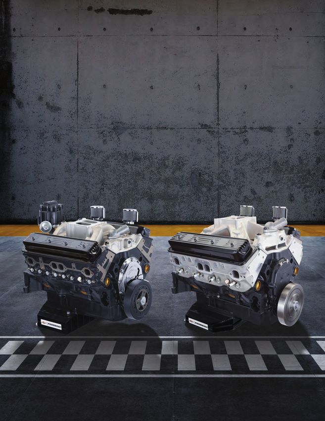
CT350 “(602)”
The CT350 (602) is rated at 350 hp @ 5400 rpm
and 396 ft lbs of torque @ 3800 rpm. It fits well in
lower level introductory classes that are looking
for affordable horsepower; such as factory stock,
modified, and truck. It comes complete intake to pan
and includes an HEI distributor. It does not include
a flywheel or water pump. The engine uses a 4 bolt
main block, cast iron crank, powdered metal rods,
and cast pistons. The 9.12:1 nominal compression
ratio with iron Vortec heads offer a good balance
of power and durability. The 8 1/2" deep oil pan
holds 8 quarts including the filter. The engine has a
dual-plane, high-rise, aluminum intake. This engine
weighs 451 lbs as delivered.
CT400 “(604)”
The CT400 is rated at 404 hp @ 5800 rpm and
makes 406 ft lbs of torque @ 4600 rpm. It fits well
in late models and other classes that run on longer
tracks. The engine comes complete intake to pan.
It does not include distributor, flywheel, or water
pump. The 4 bolt main block, steel crank, powdered
metal rods, and high-silicon pistons make a great
foundation. The 9.72:1 nominal compression ratio
with “Fast Burn” aluminum heads and roller rockers
make great power and lots of torque. The 7" deep oil
pan holds 8 quarts including the filter. This engine
has a high-rise, single plane, aluminum intake
manifold. This engine weighs 466 lbs as delivered.
| 7
INSTALLATION INSTRUCTIONS
    Each engine comes with detailed instruction sheets. This section includes some of the information that
    is included in those instruction sheets. It is imperative that the startup procedures are followed before
    starting the engine. Failure to do so may result in catastrophic engine failure. These procedures are
    designed to ensure engines are properly broke in for maximum engine life. Two key factors affect engine
    life; proper valve lash and keeping rpm’s within specified limits.

    Valve Lash
    Valve lash is critical. Read the procedures closely. To ensure that a sufficient amount of oil is available to
    cool the valve springs and pull heat from the valves, restrictors are not installed into the oil galleries.

    Break-In Procedures
    Chevrolet has detailed break-in procedures to help ensure the life of your engine is maximized. Failure to
    follow these break-in procedures will reduce the life of the engine. Make sure you read these instructions
    completely before attempting to start your new engine.

    Tune Up Specifications
    Tune up specifications are provided for each engine to insure that they are tuned to factory specifications.
    Altitude, humidity, and other factors will affect performance. Do not increase timing more than factory
    recommendations. The CT engines have had extensive dyno & track testing to maximize horsepower and
    durability using these parameters. Optimal performance can be achieved if you keep the tune-up within
    factory recommendations.

    RPM Limits
    RPM limits are critical to engine life. Catastrophic engine failure can occur if the engines are run above the
    factory recommended limits. Extensive dyno & track testing has determined the limits of the engine. Under
    no circumstances is it recommended to exceed these limits. Chevrolet recommends that all sanctioning
    bodies, track operators or promoters have rev-limits written in their rule book.

    Maximum limit for 602 engine is 5500 rpm.

    Maximum limit for 604 engine is 5800 rpm.

8   |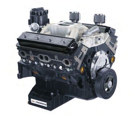
VALVE LASH PROCEDURE
It is imperative to set lash properly on circle track crate engines. The recommended lash is 1/2 to 3/4
when the engine is at normal operating temperature. To properly set the valve lash, warm up the engine to
normal operating temperature (180°-190°F) and follow the procedure below. Remove the valve covers and
disconnect power to the Distributor.

Set the valve lash as follows:

   1.   Loosen the rocker arm adjusting nut until the pushrod rotates easily.

   2. Loosen/back off the set screw inside the rocker arm nut 1/2 turn (counter-clockwise).

   3. Then, set the valve lash by tightening the rocker arm adjusting nut while rotating the pushrod
      between your fingers until you feel it stop rotating. When it stops rotating easily, you are at “zero”
      lash. NOTE: It is critical to ensure that the tip of the pushrod is seated in the pushrod cup in the
      rocker arm and the valve stem tip is located in-between the self-aligning roller tip of the rocker arm.

   4. Next, turn the rocker arm adjusting screw 1/2 turn clockwise.

   5. Then, tighten the set screw inside the rocker arm nut against the rocker arm mounting stud.

   6. Next, rotate the rocker arm adjusting nut and the set screw (clockwise) at the same time 1/4 turn
      maximum. This will allow the set screw to lock properly at hold the valve lash at 1/2 to 3/4 turn
      (total).

   7.   Use the sequence below to adjust each rocker arm. NOTE: It is critical that the lifter is on the base
        circle of the camshaft to ensure that the lash is set properly.

Valve Lash Adjustment:

   1.   Position engine at Top Dead Center (TDC) on # 1 cylinder in firing position.
        Adjust Intake valves on # 2 & # 7 cylinders.
        Adjust Exhaust valve on # 4 & # 8 cylinders.

   2. Rotate Crankshaft 1/2 Revolution Clockwise.
      Adjust Intake Valves on # 1 & # 8 cylinders.
      Adjust Exhaust Valves on # 3 & # 6 cylinders.

   3. Rotate Crankshaft 1/2 Revolution Clockwise to #6 cylinder in firing position.
      Adjust Intake Valves on # 3 & # 4 cylinders.
      Adjust Exhaust Valves on # 5 & # 7 cylinders.

   4. Rotate Crankshaft 1/2 Revolution Clockwise.
      Adjust Intake Valves on # 5 & # 6 cylinders.
      Adjust Exhaust Valves on # 1 & # 2 cylinders.

   5. Reinstall valve covers, connect distributor and start engine to check for loose valve lash.

                                                                                                                |   9
RECOMMENDED BREAK-IN PROCEDURE
  Start-up is critical to help ensure engine life. This procedure was written with the intent to provide a quick
  reference and guideline to starting a new or rebuilt engine if a dyno is not available. If you are using a dyno,
  refer to the dyno operator’s guidelines for startup and initial break in of the engine.
  Chevrolet Performance recommends the use of an established Dyno facility/Engine supplier for best results.

       1.   Safety First! Make sure you have proper tools as well as eye protection. If the car
            is on the ground, be sure the wheels are chocked and the transmission is in neutral.

       2. Be sure to check the oil level in the engine and prime the oil system. The engine should be primed
          with oil prior to initial startup. To prime the engine, first remove the Distributor to allow access to
          the oil pump drive shaft. Install the oil priming tool (part #141-955 from our licensed partner www.
          factoryperformanceparts.com) and follow the instructions included with the tool. Using a 1/2" drill
          motor, rotate the engine priming tool clockwise for three minutes. While you prime the engine,
          have someone else rotate the crankshaft clockwise to supply oil throughout the engine and to all
          of the bearing surfaces before the engine is initially started. This will ensure that oil gets to all of
          the bearings before you start the engine for the first time. Also, prime the engine if it sits idle for
          an extended period of time. Install the Distributor as follows: (1) Locate cylinder #1 Top Dead Center
          (TDC). (2) Rotate the engine to 12 degrees before Top Dead Center (BTDC). (3) Align the Rotor with
          the cylinder #1 terminal on the Distributor.

       3. Run the engine between 2,000 and 2,500 rpm with no-load for first 30 minutes.

       4. Refer to valve lash procedure and lash valves.

       5. Adjust the distributor timing to recommended specifications.

       6. Adjust Carburetor settings. Idle mixture screws, base idle, floats, etc.

       7.   After first 30 minutes of the engine running, re-set ignition timing and carb adjustments.

       8. Drive the vehicle at varying speeds and loads for first 30 laps. Be sure not to use a lot of throttle or
          high rpm’s.

       9. Run 5-6 medium-throttle accelerations to about 4500 rpm and closing the throttle (letting off the
          gas) in gear and coasting back down to 2000 rpm.

       10. Run a couple of hard-throttle acceleration to about 5000 rpm then closing the throttle (letting off
           the gas) in gear and coasting back down to 2000 rpm.

       11. Change the oil and filter with Mobil 1 Synthetic oil (P/N 12347284) and AC Delco oil filter PF1218
           (P/N 25160561 or 19431429) or PF454 (P/N 12708762 or 19432234).

       12. Drive the next 25 laps without high rpm’s (below 5000 rpm), hard use, or extended periods of high
           loading.

       13. Change the oil and filter again.

       14. Your engine is now ready for racing.

10 |
TUNE UP SPECIFICATIONS
Tune Up Specifications
Description (Engine) CT350 (602) CT400 (604)
Firing Order: 1-8-4-3-6-5-7-2
Recommended Fuel: 92-93 Octane Unleaded
Spark Advance (Ign. Timing): 32 deg @ 4000 36 deg @ 4000
Recommended Carburetor: Holley 650 HP p/n 80541-1
Baseline Jetting: Front / Rear 73 / 73 73 / 73
Spark Plugs: MR43LTS MR43LTS
Spark Plug Gap: .045" .045"
Recommended Oil: Mobil 1 Racing 0W-50 or Mobil 1 Racing 15W-50 (12347284)
Recommended Filters: AC PF-454
Recommended Valve Lash: 1/2 to 3/4 turn past 0 lash
Recommended Header Size: 1-5/8" or 1-3/4" dia. header with
3-1/2"collector 33" total length.
Notes:
| 11TUNE UP SPECIFICATIONS (CONTINUED)
Carburetor & Adjustments
The Holley 80541-1 carburetor is rated at 650 cfm. After installing your carburetor, make sure the float
Track testing showed the 650 HP series is the best levels are set properly, the idle mixtures adjusted,
carburetor choice for most applications. A 750 cfm and idle rpm set. Depending on the weather and
HP series carb was also tested. altitude you may have to change the jet size up or
down. Do not make large jumps in jet sizes without
Because both engines make power well before consulting the carburetor manufacturer or an
5500 rpm, the larger carburetor can actually hurt engine builder. Most of the time only a couple of jet
performance. The Holley HP series is designed sizes is all that is necessary for proper performance.
with most racing modifications done. There are Make sure you take care of the carburetor when the
other very good high performance aftermarket season ends. Drain the fuel and put the carburetor
carburetors available as well that may be used with in a plastic bag or sealed container. Do not leave it
proper testing and tuning. on the engine, the fuel will evaporate and leave a
residue in the metering galleries.
Ignition Timing (Spark Advance)
A maximum of 32 degrees of advance is it doesn’t take much timing to make power. Don’t
recommended for the CT350 and a maximum of 36 run more than the recommended maximum spark
degrees of advance is recommended for the CT400. advance as detonation can occur.
The combustion chambers are very efficient so
Fuel Requirements
91-93 Octane Unleaded fuel is recommended. It is little value. The valve seats are designed to run on
not beneficial to run leaded fuel or 101-104 octane. unleaded fuel. Some of the tracks & sanctioning
Leaded fuel contaminates the oil and can foul the bodies add traces of lead for “Off Road Use” which
spark plugs. All three engines have compression should not affect performance.
ratios of 10:1 or less, so the higher octane is of
Headers
As part of Chevrolet’s dyno testing, the engines were tested with both 1-5/8" or 1-3/4" diameter primary
tube headers. The total length was approximately 33" with a 3 1/2" collector.
Recommended Oil
Chevrolet conducted dyno testing of the engines with Mobil 1 Racing 0W-50 or Mobil 1 Racing 15W-50 (12347284)
synthetic oil. Extensive testing has proved that synthetic oil provides better lubrication qualities under extreme
conditions and has a longer life between oil changes.
12 |ENGINE COMPONENTS
The engines are subjected to grueling dyno durability testing. Quality control standards are maintained
during assembly of each engine. This section covers some of the differences between the major components
in the two engines.
Engine Blocks
Both engines are assembled with brand new 4 bolt main blocks with cast iron caps. The main caps have
in-line bolts. They are machined to factory specifications and tolerances. The blocks are designed to use
a 1 piece rear crankshaft seal. The photo to the right below shows the 1 piece rear seal adapter that was
designed to reduces oil leaks. A flywheel that is balanced correctly require for these applications.
P/N 14088556 rear seal retainer
Pistons
The piston on the left (below) is installed in CT350 (602) engines. This piston has a grafal coating on the
skirt. It's a cast aluminum dished piston with 4 valve reliefs.
The piston on the right (below) is installed in CT400 (604) engines. It’s a flat top piston with 4 valve reliefs
made from high-silicon aluminum.
| 13ENGINE COMPONENTS (CONTINUED) Crankshafts In 2010, the CT400 Circle Track engine began Below left [ Fig A ] is an image of the original being built with a second design crankshaft. This crankshaft. This crankshaft was used from 2002 change was due to a material change the crank until mid-year 2010. Note the As-Cast appearance was being manufactured with and does not affect of the rod end throws as compared to the new engine performance. To maintain rotating assembly crankshaft below right [ Fig B ] with machine rod balance without having to change any other parts end throws. This new crankshaft was first used in of the rotating assembly, the ends of the connecting mid 2010 and replaced in 2021. rod throws have been clipped [machined]. The new and old crankshafts will look different during Starting in 2021 CT350 and CT400 both use a Forged inspection. steel Crankshaft. Fig A Fig B 14 |
ENGINE COMPONENTS                                                                             (CONTINUED)

Harmonic Balancer / Torsional Damper

                                                     The current balancer has
                                                     timing marks on both edges
                                                     of the outer ring. This allows
                                                     for the use of different timing
                                                     pointers and may assist
                                                     in reading the timing light
                                                     pulses in installations where
                                                     clearance is minimal. The
                                                     balancer is 8 inches and sold
                                                     under P/N 19301706.

         ZZ6 and CT400
        Engine Balancer

Intake Manifolds

P/N 12366573 intake manifold (above) is used on           P/N 12496822 intake pictured (above) is used on
CT350 (602) engines. It’s a dual-plane, high-rise         CT400 (604) engines. It is single-plane, high-rise
intake. It has the 8 bolt Vortec mounting pattern.        intake. It has the 8 bolt Vortec mounting pattern.

                                                                                                               | 15
ENGINE COMPONENTS (CONTINUED) Cylinder Heads P/N 12691728. The pictures above show the cast iron cylinder head & combustion chamber used on the CT350 (602) engine. Head casting number is 10239906 or 12558062. Valve sizes are 1.94" intake & 1.50" exhaust. P/N 19417592. The pictures above show the aluminum “fast burn” cylinder head and combustion chamber used on the CT400 (604) engines. Head casting number is 19417568. Valve sizes are 2.00" intake & 1.55" exhaust. In early 2014, the cylinder head assembly was updated to utilize the LS3 Beehive conversion kit which resulted in a more robust valvetrain which typically does not need to be replaced for an entire season or more of racing. Push Rods GM uses part number 14044874 HD .075" wall pushrods in the CT350 (602) engines. The pushrod is 7.724" long and 5/16" diameter. P/N 10241740 is used in CT400 (604) engines. It is a HD pushrod that has a 0.060" wall and 7.122" long and 5/16" diameter. 16 |
CT400 (604) INTAKE MANIFOLD GASKET
REVISION HISTORY
Below is a an image of the original intake gasket P/N 89017465 (kit includes 2 gaskets). This gasket was used
from 2002 until mid-year 2012. Pictured below is the replacement gasket P/N 12497760 which was used
since mid-year 2012 and was re-instated in the Fall of 2021 (see below). China wall sealant used with this
gasket could be any of 3 different colors, Light Gray, Dark Gray, or Black.

Picture below is the replacement gasket P/N 12497760 that was used from mid-year 2012 until the Fall of
2013. This P/N was superseded to P/N 19301685 (See below). This P/N 12497760 is again sold as a kit with
2 gaskets included. China wall sealant used with this gasket could be any of 3 different colors, Light Gray,
Dark Gray, or Black.

Beginning Fall of 2013, a redesigned intake manifold gasket went into production on the CT400 (604). This
gasket is designed to closely match the intake ports of the Fastburn Aluminum cylinder heads. This gasket
also incorporates the print-o-seal sealing beads around the port for increased sealing. Below is a picture of
the new gasket kit P/N 19301685 (kit includes 2 gaskets). This new gasket was the suggested replacement
gasket to be used for all repairs and or rebuilding/refreshing of all 604’s until the Fall of 2021. This gasket
was found to be difficult to maintain placement during build and a return to the original gasket 89017465
was implemented in the Fall of 2021.

In October of 2015, Chevrolet Performance began to apply a thin bead of RTV (Loctite 5900) to the cylinder
head around the coolant and intake port openings to mirror the print-o-seal sealing beads on the gasket.
This was implemented to ensure that the intake manifold gasket remains in the installed position and
improves the sealing of the intake ports under high manifold vacuum conditions.

                                                                                                             | 17
ENGINE COMPONENTS (CONTINUED)
Front Covers
Chevrolet uses two different types of front covers on the two engines. The photo on the right shows a
stamped steel cover that is installed on CT350 (602) engines. The photo on the left shows the plastic cover
that is installed on CT400 (604) engines.
12562818 plastic cover 12342089 steel cover
Rocker Arms
The 2 photos above show the stamped steel rockers and the 2 different kool nuts (positive locking nuts) that
have been installed on the CT350 (602) engines. The 2 kool nuts are slightly different in appearance but
performance is identical. Valve Lash/Rocker arm adjustment is critical. (See page 9)
This photo shows the aluminum roller rocker arms that are
installed on CT400 (604) engines.
CT350 (602) engines use stamped steel rocker arms.
Valve Lash/Rocker arm adjustment is critical. (See page 9)
18 |ENGINE COMPONENTS (CONTINUED)
Oil Pans
The CT350 (602) engine uses an 8 quart pan (including filter) that is 8" deep. The sump is 9 1/2" long and
11" wide. It fits stock front subframe cars (with stock engine location). The right side of the pan is kicked
out 3 1/4" and has 3 trap doors to control oil. It has a built-in crankshaft scraper and comes with a louvered
windage tray.
The CT400 (604) engine uses an 8 quart pan (including filter) that is 7" deep. The sump is 12" long and 14"
wide. It fits stock Camaro front subframe and most fabricated subframe (with stock engine location). It has
6 trap doors for oil control, 3 crankshaft scrapers, oil temp fitting and a louvered windage tray. Below is a
photo of the louvered windage tray.
Photo of the CT400 (604) oil pan. Photo of the louvered windage tray.
| 19ENGINE SPECIFICATIONS This section covers recommended rebuild specifications. Both engines are assembled with brand new parts. The engines are assembled to tight tolerances to ensure the horsepower differences between the engines is minimal. Customers typically are able get 2 seasons of service from each new engine. Chevrolet does not recommend rebuilding engines. We recommend purchasing a new engine. This will ensure 100% integrity of the program. If rebuilds are allowed, it is up to the track owner or sanctioning body to manage the rebuilders and closely monitor the rebuilt engines. The key to maintaining close competition between new engines and rebuilt engines is to make sure rebuild specifications are kept close to factory tolerances. These specifications are only guidelines. If the engine is rebuilt to these specifications minimal horsepower differences should be noticed. These specifications also provide a reference point for inspection of suspected modifications to the factory engine. The machining of the valve seat angles and depths are critical to the valve durability and the performance of the engine. In addition to the effect on airflow, the contact area between the valve and the valve seat is the primary method of removing heat from the valve. Excessive valve temperatures negatively impact the durability of the valves. Exceeding the maximum recommended engine speed (RPM) can significantly damage the valvetrain components. The maximum engine speed limits were established through extensive valve train testing. Do not exceed the recommended RPM limits. The following page covers the details of the valve seat area. These are the factory machining specifications. Anytime the valve seat and valve is “touched up” it may affect the height of the valve in the combustion chamber. Refer to the page on valve spring specifications for physical parameters of a new spring. Valve springs will typically lose stiffness (rate) during operation of an engine. The major factor in reducing valve spring life is heat, therefore, no oil gallery restrictors are installed in the engine. Oil restrictors are not necessary when the engine speeds are kept within factory recommendations. Both engines have excellent provisions for draining oil back to the pan. As long as the breathers are functioning properly and the engine has minimal ring blow-by, oil drainage to the pan will be good. Some engine builders have learned from experience the negative effects that improper valve seat machining has on the engine. Make sure your engine re-builder follows these specifications. 20 |
ENGINE SPECIFICATIONS                                                               (CONTINUED)

Factory Engine Specifications - New
Description                                    CT350 (602)          CT400 (604)
Engine Weight (As Sold)                        517 Lbs              470 Lbs
HP                                             350 @ 5400 rpm       404 @ 5600 rpm
Torque                                         396 @ 3800 rpm       406 @ 4600 rpm
Bore                                           3.998" - 4.001"      3.991" - 4.001"
Compression Ratio                              9.12:1               9.72-1
Block Type                                     Cast iron            Cast Iron
Casting Number                                 See Note Below       10243880
Deck Height                                    9.025" +/- .001"     9.025" +/- .001"
Crankshaft Type                                Forged Steel         Forged Steel
Crankshaft Casting Number                      12691722             12670965
Crankshaft Rear Seal Type                      1 pc                 1 pc
Crankshaft Weight                              55.30 lbs            55 lbs
Piston Type                                    Cast Aluminum        Hi-Silicon Alum
Diameter                                       3.996"               3.998" - 3.999"
Valve Relief Type                              4 reliefs            4 reliefs
Dished or Dome                                 Dished               Flat
Piston Weight                                  594 Grams            533 Grams
Connecting Rod Length                          5.7"                 5.7"
Connecting Rod Weight +/- 10.0 grm             604.15 Grams         604.15 Grams
Camshaft Type                                  Hyd                  Hyd Roller
Camshaft Lift (int / exh measured @ valve)     .435" / .460"        .474" / .510"
Camshaft Lobe Lift: ( int / exh)               .290" / 306"         .316" / .340"
Duration @ .050” ( int / exh)                  212 / 222            208 / 221
Camshaft Lobe Centerline                       112.5 degrees        112 degrees
Rocker Arm Type                                Stamped Steel        Roller Rocker
Rocker Arm Ratio                               1.5                  1.5
Head Gasket Type                               Composite / Steel    Composite
Thickness                                      .028"                .051"
Cylinder Head Type                             Iron Vortec          Aluminum
Casting Number                                 12558062             19417568
Valve Sizes                                    1.94" / 1.50"        2.00" / 1.55"
Combustion Chamber CC’s (+/- 1-2 cc)           64                   62
Intake Port CC’s ( +/- 1-2 cc)                 170                  205
Exhaust Port CC’s ( +/- 1-2 cc)                                     77
Normal Oil Pressures                           40psi @ 2000 rpm     40 psi @ 2000 rpm
Note: * signifies 19258602 engine part specification
No Deck Surfacing after 1st Rebuild
No Angle Milling of Cylinder Heads to Increase Compression Ratio.
No Modifications to: Crank, Rods or Pistons.

                                                                                              | 21
ENGINE SPECIFICATIONS (CONTINUED)
Recommended Rebuild Specifications & Tolerances
Description CT350 (602) CT400 (604)
Maximum Bore Allowed: Maximum of .008” all Bores
Otherwise new block required
Standard Block Deck Height +/-.001" 9.025" 9.025"
Maximum Deck Surfacing of Block .005" .005"
Minimum Block Deck Height +/- .001" 9.020" 9.020"
Minimum Crank Bearing Size: .010" under .010" under
Minimum Rod Bearing Size: .010" under .010" under
Minimun Rod Weight: 595 grams 595 grams
Crankshaft Balancing: Factory External Factory External
Maximum / Minimum Crank Stroke: 3.48" 3.48"
No offset grinding of crank during rebuild
No Modifications Allowed to: Crank, Rods or Pistons
Maximum Deck Surfacing of Head: .005" to Square Surface During 1st rebuild
No Deck Surfacing After 1st Rebuild.
Rebuild Sealing Bolts:
Contact your local track and/or the track’s NOTE: GM does not provide RM bolts for resealing
authorized rebuilder when you need to have your rebuilt engines. If your track is going to allow rebuilds,
engine serviced. They will be responsible for they should use an alternate sealing method .
resealing the engine for competition and may wish
to incorporate their own sealing methods.
22 |ENGINE SPECIFICATIONS (CONTINUED)
Valve Spring Specifications
Below is illustration of a typical valve spring. Match up the locations and engine part number with the chart
below for the correct specification.
Note: These specifications are for new valve
springs. The specification chart shows free height,
installed height, spring o.d., installed pressure,
open pressure, etc.
Keep in mind that new spring pressures have some
variances. The chart notes the two important
variances. Installed pressure & open pressure.
Valve spring pressures will change depending on
length of time engine is in service, temperature
during that period, and if the engine has been
excessively over-revved. It is acceptable to add
maximum of a .020" shim when valve seats are
recut or to get spring pressures back to proper
factory specifications. Care must be taken to make
sure retainer to guide clearance is adequate. No
Titanium Retainers Allowed.
Description CT350 (602) CT400 (604)
Valve Spring P/N 10212811 12551483
Diameter (A) 1.250" 1.32"
Free Height (B) 2.021" 2.154"
Installed Height (C) 1.70" 1.78"
Lbs @ Installed Height (+/- 4 lbs) (D) 80 lbs 101 lbs
Open Height (E) 1.270" 1.300"
Open Pressure (+/- 8 lbs) (F) 195 lbs 260 lbs
Coil Bind (G) 1.20" 1.21"
Wire Diameter .177" .178"
| 23ENGINE SPECIFICATIONS (CONTINUED) CT400 - Beehive Valve springs The more recent versions of the CT400 (604) engine utilize Beehive style valve spring which is superior to other type springs for this application. It is lightweight and adds stability to the valve train. It is 1.27" in diameter at the bottom, 1.06" at the top and 1.780" installed height. Spring pressures are 98lb +/- 4.5 lb. installed and 267 lb. +/- 13 lb. at .480 valve lift (1.300 open height). Spring retainers, keepers, and seats are unique to this valvetrain and must all be used together. P/N’s listed in graph below. CT 400 Beehive Springs for Fastburn Heads Valvespring P/N 12713265 free ht. 2.122" inst. ht. 1.780" Lbs. @ installed ht. (+/- 4lbs) 98 +/- 4.5 lbs. open ht. 1.300" open pressure (+/-8lbs) 267 +/- 13 lbs. coil bind 1.210" wire diameter Ovate [ 4.29 x 5.37 ] Retainer 19303149 (8 Pk ) mass 11.9g Keeper 19302868 ( 16 Pk ) mass 3.9g Spring seat 19303150 (8 Pk ) Valve spring service 12499224 (16 Pk ) 24 |
ENGINE SPECIFICATIONS                                                                    (CONTINUED)

CT350 (602) Engine Camshaft Specifications
P/N 24502476 camshaft is installed in a CT350 (602) engines. It is a flat tappet camshaft and uses standard
hydraulic lifters. See section on valve lash for proper lash procedure.

Valve Lift: .435 intake and .460 exhaust.
Duration @ .050": 212 degrees intake and 222 degrees exhaust.
Cam lobe centerline is: 112.5 degrees.
Intake lobe lift .290".               Exhaust lobe lift .307"
Intake base circle radius: .633"      Exhaust base circle radius: .616"
Dowel pin hole: Retarded 5 degrees from centerline of # 1 cylinder exhaust lobe, advanced 107.5 degrees
from centerline of # 1 cylinder intake lobe. (107.5 +5 = 112.5 degrees lobe separation.)
Note: +/- .010" all dimensions and +/- 5 degrees angularity.

Shown below is a graph of the cam profile for cam p/n 24502476 as used in CT350 (602) engines.

24502476 camshaft specifications

                                                                                                         | 25
ENGINE SPECIFICATIONS (CONTINUED) CT400 (604) Engine Camshaft Specifications P/N 10185071 camshaft is installed the CT400 (604) engines. It is a roller camshaft design and uses hydraulic roller lifters. This camshaft has a red dab of paint located near the camshaft gear for identification. See section on valve lash for proper lash and procedure. Valve Lift: .474" intake and .510" exhaust. Duration @ .050": 208 degrees intake and 221 degrees exhaust. Cam lobe centerline is: 112 degrees. Intake lobe lift .316". Exhaust lobe lift .340". Intake base circle radius: .60684" Exhaust base circle radius: .583". Dowel pin hole: Retarded 5 degrees from centerline of # 1 cylinder exhaust lobe, advanced 107 degrees from centerline of # 1 cylinder intake lobe. (107 +5 = 112 degrees lobe separation) Note: +/- .010" all dimensions and +/- 5 degrees angularity. Shown below is a graph of the cam profile for cam p/n 10185071 as used in the CT400 (604) engines. 10185071 camshaft specifications 26 |
TORQUE SPECIFICATIONS & SEALERS                                        (CONTINUED)

Cylinder Head Torque Sequence

                                             The diagram to the left shows the proper
                                             torque sequence for both engines.

                                             Torque bolts to 65 ft lbs. (Torque @ 40 ft
                                             .-lbs., then 50 ft.-lbs. and 65 ft.-lbs. final
                                             pass.) Use 19333512 Teflon sealer on all
                                             bolts unless new.

Intake Torque Sequence for CT350 (602) and CT400 (604) Engines

                                             The torque sequence to the left is for
                                             intakes used on CT350 (602) and CT400
                                             (604) engines

                                             Torque all bolts to 10 ft.-lbs. Then torque
                                             all bolts to 18 ft.-lbs. Use 19333512 Teflon
                                             sealer on bolts unless new. Let intake set
                                             for a short period of time and re-torque
                                             to 18 ft.-lbs.

                                                                                         | 27
FLYWHEEL & TRANSMISSION COMPONENTS
This section is intended to identify the flywheel cannot use a 400 flywheel on circle track engines.
components that GM recommends. The aftermarket The balance is in a different location and the bolt
has designed small clutch packs that fit smaller bell pattern is different. You must use the correct,
housings used in some applications. This section will balanced flywheel.
also will help clarify the confusion between 1-pc &
2pc rear seals and flywheel balance. The front balancers on the circle track crate
engines are zero balanced. Therefore the internal
Both circle track crate engines use 1pc rear seals. components of the engine are zero balanced like
It’s a much better seal and was introduced in a pre 1986 engine. The only difference is the rear
production engines in 1986. When using a 1pc rear flywheel has a counterbalance. This is because
seal, the flywheel must have a counterbalance. All the rear of the crankshaft is machined for the 1pc
three engines are “internal/external” balanced. seal. One-piece rear seal engines do not have the
It’s not like the old 400 engines. They had both counterbalanced flange like pre 1986 engines.
a counterbalanced flywheel and balancer. You
Photo to the left shows a flexplate that fits the CT engines.
The counterweight is shown in the 10 o’clock area of the photo.
It is welded in the proper location which makes sure the engine
balance is correct.
Make sure whatever flywheel you use has a counterbalance on
it or the engine will have a vibration.
This photo shows an aftermarket drive hub.
It combines the ring gear, transmission input spline and proper
counterbalance location.
This is a great photo of how one aftermarket manufacturer
address’s the external balance required at the rear of the engine.
When the one piece seal was introduced, GM implemented a change to the bolt pattern diameter. The bolt
pattern diameter changed from 3 1/4" to 3". This was done to ensure that older flexplates would not be
installed by mistake and cause imbalance issues. Make sure if you are using an aftermarket component, it
has the correct balance.
28 |FLYWHEEL & TRANSMISSION COMPONENTS
Description CT350 (602) CT400 (604)
Transmission Installation Components
Flexplate 12-3/4" 153 tooth Automatic 14088765 14088765
Flexplate 14" 168 tooth Automatic HD 12554824 12554824
Flexplate 14" 168 tooth Automatic 14088761 14088761
Flywheel 12-3/4" 153 tooth standard 14088650 14088650
Flywheel 14" 168 tooth Std 14088648 14088648
Flywheel 14" 168 tooth lightweight 14088646 14088646
Note: 14088646 weighs approximately 15 lbs.
Pilot Bearing 14061685 14061685
Pilot Bushing 10125896 10125896
Dowel Pin, Bellhousing (2) - 12720455 (2) - 12720455
Starter, Standard Duty 1876552 1876552
Starter, 153 tooth 93-97 F body LT1 10465143 10465143
Bolt, Starter Long (fits 10465143) 14097278 14097278
Bolt, Starter Short (fits 10465143) 14097279 14097279
Bolt, Flywheel (6) - 12337973 (6) - 12337973
Bolt, Flexplate (Automatic) (6) - 03727207 (6) - 03727207
Torque Specifications
Flywheel Bolts 65-70 ft lbs 65-70 ft lbs
Starter Bolts 35 ft lbs 35 ft lbs
The photo to the left shows a p/n
14061685 crankshaft bushing.
Install this roller bearing bushing
in the rear of the crankshaft to
minimize friction losses.
| 29TECH INSPECTION PROCEDURES (CONTINUED)
Info-Glyph Inspection Procedure:
Info-Glyph is a process developed for anti- bolts. You only need 40-60% of the dots visible to
counterfeiting in which an encrypted message is decode the encrypted message. With the proper
placed within with a series of dots. GM introduced software, inexpensive digital notebook camera and
this technology in late 2005 on circle track sealing laptop, the Info-Glyph can be decoded.
Additional Sealing & Tracking Methods:
There are several other ways to seal and track serviced. The local track can issue serial numbers
engines. Some are simple, and some are more and stamp them on the block and heads. That
complex. By adding another level of seals, this engine will be required to be registered on the track
reduces chances the engine is modified. web site. This will allow the track to determine
how long an engine is in service and who owns it. A
Tracking engines by serial numbers is the best way registration fee maybe required to cover overhead
to understand who has what engine and when it is costs.
Drilled bolt seals
You can install additional seals by installing a couple of drilled bolts in
key locations (intake, front cover & oil pan) then run a stainless wire
between the bolts and use a crimp seal. The crimp seal can be as simple
as the track logo on a pair of vice-grips where you crimp a large fishing
sinker. Some bolts can be purchase off the shelf already drilled, making
installation easier.
Shown is Drill bolt fixture,
stainless wire & safety wire pliers.
Wire Lock Seals.
One of the major sanctioning bodies uses seals that involve a seal
that locks the wire inside preventing removal. It also has enough area
on the lock to serialize and/or add a logo. This sanctioning body has
tough rules regarding rebuilds does extensive tech inspections. There
resealed engines are monitored closely. They also use the cup plug as
shown below as a secondary seal. Both seals are marked, serialized
and registered.
Shown is a Wire lock seal.
www.vmsproducts.net
www.stoffel.com
Cup plug seals
This method uses a special base that is secured and/or a logo added. They are simple to use when
by the bolt. A cap is pressed on to the base and a standard size bolt is required. It is more difficult
encapsulates the bolt head. Fingers on the base grab when you have specialty bolts or in tight areas.
the outer rim of the cup and prevent removal without www.americancasting.com
signs of damage. These seals can be serialized
30 |TECH INSPECTION PROCEDURES (CONTINUED)
Cup plug system that can be serialized and track logo installed
One of the earliest series to embrace the circle track crate engine program was the USPRO Series, now
known as the ASA Late Model Series. GM Racing and Chevrolet Performance Parts has worked with them to
provide some of the procedures listed below. Refer to the actual instructions from each manufacture for
100% accuracy of the test procedures. These are only guidelines.
P&G Procedure: www.precisionmeasure.com
The P&G tester is one of the best “on site checks” of checking engine displacement. It provides a means to
check engine displacement without tearing down the engine.
Note: Engine temperature is critical with this test.
Whistler Procedure: www.katechengines.com
The Whistler is used to check compression ratio. It’s a tool used to check compression ratio of completely
assembled engines at the track. Note: Engine temperature is critical with this test.
Valve Spring Inspection: www.moroso.com
Valve springs are an area that teams try and increase the spring pressure to increase RPM limits of the
engine. This sheet covers a quick way to check spring pressures on the engine. Refer to the spring chart for
proper specifications. Moroso P/N 62391 spring rate checker.
| 31P&G TEST PROCEDURE
The P/G tester is used to check engine displacement. This is a quick on-site tool for checking displacement
to determine if it is in the allowable cubic inch range.
Important Information
The P/G tester must be kept clean. Before each use, lubricate
the nylon piston, tube and o-ring with fine oil. If tester is to be
used for continuous testing, it should be oiled after every tenth
(10th) engine is checked.
Engine Preparation
• Remove all spark plugs.
• Select the cylinder number to be checked.
• Have the crew chief remove the both rocker arms and both
push rods from selected cylinder.
Testing Procedures
• Insert the spark plug screw adapter into the selected
cylinder. If this operation is done by the crew chief, make
sure that no washers or spacers are added to the adapter.
• Make sure that the nylon piston is bottomed out in the
tester tube. Insert the push rod gently into the tube and
slide the piston to the bottom of the tube.
• Note the engine temperature as this will be needed to
determine the total cubic inch displacement and for the
Whistler Test.
• Important – If the engine is cold, use the same temperature as the outdoor temperature to read the
listed cubic inch number adjacent to the temperature. If the engine temperature is warmer than the
outdoor temperature read the % correction factor on the chart.
• With the ignition off, crank the engine, at cranking speed for approximately 2 seconds or until the
engine has been spun at cranking speed approximately 10 times.
• Read the number where the nylon piston stops. Convert this number to cubic inch displacement using
the P&G Conversion Chart.
• Maximum allowable cubic inch displacement for Chevy is: 350.0
à If on conversion from P&G Conversion Chart is larger than maximum allowable reading, retest
immediately. If reading is still over the legal maximum allowable limit, the Whistler Test or cc testing
of the heads is necessary.
32 |WHISTLER PROCEDURE
The Whistler measures combustion chamber volume. Using the volume achieved with the tester along with
the chart provided by the company, you will know the correct engine displacement.
Measuring Combustion Chamber Volume for Engine Displacement
Requirements
• 110v Power supply
• Portable Air Tank or Compressor
Engine Preparation
• Remove spark plug
• W ith ignition off and distributor unplugged, crank engine to locate
Top Dead Center (TDC) of piston in selected cylinder.
• P urge any remaining gas vapors from selected cylinder using
compressed air.
• Insert Whistler adapter into spark plug hole.
•W hen selecting cylinder to test, be aware that some engines require
the removal of the header to accommodate the insertion of the
whistler probe.
• Check water temperature via gauge or thermometer.
Testing Procedures
• Plug Whistler into 110 volt power supply.
• Turn on Whistler
• Adjust display as follows:
à Re-Set the 3 switches as follows.
• Left hand switch – set for numbers 4-6-8.
• Center switch has 3 functions.
à Center position – Set Temperature of engine.
à Bottom position – Set displacement as determined by P&G test.
• Maximum Reading for Chevy: 350.0
• Top Position – this is where the actual reading will appear.
à Right hand switch is used to set reading – either up or down to change readings.
• Once the engine temperature and engine cubic inches have been entered – move the center switch to top.
• Insert whistler probe into adapter in selected cylinder.
• Make sure that the piston is at TDC.
• Hook up air line to portable air tank.
• Adjust air flow to 20 SCFH.
• Rotate engine slowly in either direction to determine if TDC has been reached.
• At TDC note the highest compression ratio reading. Rotate the engine slowly in the other direction to
determine the highest reading. Maximum allowable static reading is 10:1 as shown on the readout. If
the reading is larger, cc the heads to determine the legality of the engine.
| 33VALVE SPRING INSPECTION PROCEDURE
This section helps identify those teams that have changed valve springs in an effort to gain additional rpm’s.
It is important to keep rpm’s within GM recommended numbers. Engine life and wear is severely reduced for
every 100 rpm’s that an engine is over-revved.
Purpose
Check for proper stock valve spring specifications.
Use Moroso p/n 62390.
Step 1. Have the crew chief remove all debris in and around the
engine.
Step 2. Have the crew chief remove the valve cover being careful not
to contaminate the cylinder head.
Step 3. Have the crew chief remove both rocker arms from the
selected cylinder & make sure piston is at BDC.
Step 4. Slide the Moroso valve spring tester into position so that
intake valve spring sits in tester pocket.
Step 5. Pull the handle to compress the valve spring to full
compression and note the reading. Repeat the test for the
exhaust valve spring and note the reading.
Step 6. Refer to chart in rebuild section for correct valve spring
pressures for the intake & exhaust. Use the space below to
reference the numbers for your application.
Int.________ Exh.________
34 |ENGINE PARTS LIST
Description CT350 (602) CT400 (604)
Engine Block Components
Short Block Assembly Not Serviced 12561723
Cylinder Block 19431835 19431835
Main Caps Not Serviced Not Serviced
Rear Seal Retainer 14088556 14088556
Dowel Pin, Rear Crank Retainer 9441003 9441003
Dowel Pin, Front Cover (2) - 12554553 (2) - 12554553
Stud, Rear Adap. (2) - 14101058 (2) - 14101058
Nut, Rear Adap 10108645 10108645
Bolt, Rear Adap. (2) - 14088561 (2) - 14088561
Bolt, Rear Adap. 14088561 14088561
Rear Cam Plug 10241154 10241154
Cam Bearings Use p/n 12453170 for 1 &4. P/n 12453171 for #2,3,5
Dowel Pin, Bellhousing (2) - 01453658 (2) - 01453658
Crankshaft 12691722 12670965
Connecting Rod. Powdered Metal 10108688 10108688
Piston (Std) 88894280 10159436
Balancer, 8" diameter 19260269 19260269
Cylinder Head Components
Cylinder Head Assembly 12691728
Cylinder Head Bare 12691728 N/S
Intake Valve 10241743 12555331
Exhaust Valve 12550909 12551313
Valve Spring 10212811 12551483
Retainer, Valve Spring 14003974 19169661
Key, Valve Retainer 24503856 24503856
Shim, Valve Spring N/A 10212809
Stud, Rocker Arm N/S 12552126
Rocker Arm (1 per package) 10089648 19432297
Kool Nut Kit 88961233 N/A
Push Rod 14095256 10046173
Dowel Pin, Cylinder Head (4) - 585927 (4) - 585927
Intake Manifold Components
Intake Manifold 12366573 12496822
Distributor 19432312 N/A
Distributor Hold Down 19433111 19433111
| 35ENGINE PARTS LIST (CONTINUED) Description CT350 (602) CT400 (604) Camshaft Components Camshaft 24502476 10185071 Lifter 5232720 5234890 Camshaft Gear 340235 12552129 Timing Chain 14087014 14087014 Crankshaft Gear 10128346 14088784 Camshaft Thrust Retainer N/A 10168501 Timing Cover 12342088 12562818 Timing Tab 8" Balancer 3991436 3991436 Timing Tab 6 3/4" Balancer 3991435 3991435 Oil Pan Components Oil Pan 25534353 25534354 Oil Pan Gasket One Piece Design 10107676 10108676 Oil Pump 93442037 14048272 Shaft, Oil Pump Drive 19434251 3998287 Retainer, Nylon oil pump drive 3764554 3764554 Oil Pan & Screen 25534353 25534354 Reinforcement, Oil Pan LH 25534360 25534360 Reinforcement, Oil Pan RH 12553059 12553059 Adapter, Oil Filter 19299222 19299222 Bolt, Oil Filter Adapter 3951644 3951644 Engine Dress Items Rod, Fuel Pump 3704817 3704817 Cover, Fuel Pump Opening 14094069 14094069 Water Pump Cast Iron (Long) 12685965 12685965 Water Pump Alum (Long) 12495826 12495826 Water Pump Alum (Short) 19418012 14011012 Valve Cover Kit 25534359 25534359 Valve Cover Breather Kit 25534355 25534355 Miscellaneous Parts Balancer, 8" Diameter 19260269 19260269 Balancer, 6 3/4" Diameter 12551537 12551537 Key, Crankshaft Woodruff (2) - 106751 (2) - 106751 Key, Balancer Woodruff (2) - 106751 (2) - 106751 Thermostat 180 degree 12555290 12555290 Spark Plug Wires, 135 degree boot 12361050 12361050 Spark Plug Wires, 90 degree boot 19433385 19433385 Spark Plug MR43LTS 19355201 19355201 36 |
You can also read