Dynamic Skip Fire: New Technologies for Innovative Propulsion Systems Dynamic Skip Fire: Technologie für innovative Antriebe
←
→
Page content transcription
If your browser does not render page correctly, please read the page content below
DynamicSkipFire:
   New Technol
             ogiesfor
I
nnovat
     ivePropulsi
               onSystems

    DynamicSkipFire:
     Technologi
              efür
    i
    nnovati
          veAnt r
                iebe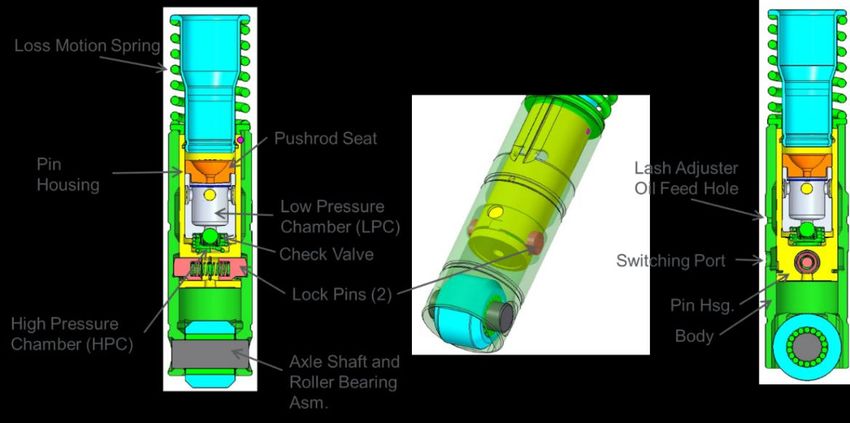
-1-

   M. Younkins PhD., E. Ortiz-Soto PhD., M. Wilcutts PhD., J. Fuerst BSME MBA, Tula
                        Technology San Jose, California, USA;
                      A. Rayl MSEE, General Motors, Milford, MI, USA:

     Dynamic Skip Fire: New Technologies for Innovative Propulsion
                              Systems
           Dynamic Skip Fire: Technologie für innovative Antriebe

Abstract
General Motors leverages Tula’s Dynamic Skip Fire (DSF®) technology to introduce an industry first
Dynamic Fuel Management (DFM) cylinder deactivation system that combines millisecond-accurate
torque control with cylinder deactivation to optimize fuel consumption of spark ignited engines. This
digitized control of every cylinder event optimizes engine operation such that peak efficiency is
obtained throughout the range of engine operation.
General Motors is launching Dynamic Fuel Management in the 2019 MY. Building on Active Fuel
Management (AFM) that was introduced commercially in 2005, DFM extends cylinder deactivation
to all cylinders in 5.3L and 6.2L V8 engines which allows for a large variety of firing sequences. In
this application of DFM, 29 firing sequences are used in steady driving conditions. Transitions
between firing densities are done in a continuous fashion. A method was developed and
implemented to reduce required time to deactivate cylinders. Emissions limits of ULEV 50 were
targeted and achieved. With production levels of noise and vibration, significant fuel economy
improvement was achieved. Final fuel consumption numbers will be communicated later this year.
Furthermore, continuing improvements to Tula’s DSF are being achieved as the automotive industry
is focused on reducing the fuel consumption of the worldwide fleet. Across the industry, additional
fuel economy technologies being pursued include electrification and improvements in combustion
and combustion strategy.
Tula’s DSF is synergistic with these strategies and more. For instance, eDSF™, realizes the
synergies between DSF and hybridization. Development taking place over a four vehicle eDSF fleet
have indicated that eDSF improves the baseline 48V hybrid performance by 8% on the WLTC.
Tula has also developed mDSF™, coupling DSF with multiple cam profiles and Miller cycle
strategies. Based on engine dynamometer experiments, Tula is projecting a 6-8% vehicle fuel
consumption reduction in certification drive cycles over a production 2-step Miller engine.
As Tula’s Dynamic Skip Fire technology is further developed with electrification, innovative
combustion strategies and autonomous technologies, significant synergistic benefits are being
realized and will be introduced.

Kurzfassung
Nach einer intensiven Bewertung durch General Motors wird Tulas Dynamic Skip Fire (DSF)
Technologie als ein Dynamic Fuel Managment (DFM) System zur Zylinderabschaltung in Serie
eingeführt. Das System kombiniert Millisekunden genaue Drehmomentenregelung mit
Zylinderabschaltung zur Optimierung des Kraftstoffverbrauchs bei Ottomotoren. Die Regelung
jedes Arbeitsspiels optimiert das Motorbetriebsverhalten, so dass der Verbrauchsbestwert in einem
weiten Kennfeldbereich genutzt werden kann.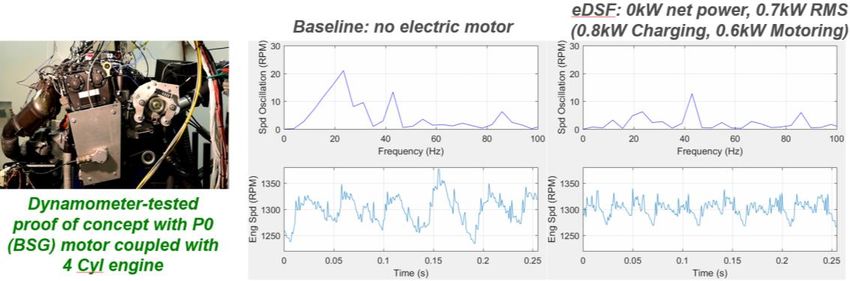
-2-

General Motors wird Dynamic Fuel Managment im Modelljahr 2019 in die Serie einführen.
Aufbauend auf dem Active Fuel Managment (AFM), das im Jahr 2005 eingeführt wurde, erweitert
DFM das System um die Zylinderabschaltung für alle Zylinder der 5,3 l und 6,2 l V8 Motoren. Dies
ermöglicht eine große Vielfalt von Zündfolgen. In dieser Anwendung von DFM kommen 29
Zündfolgen im stationärem Motorbetrieb zum Einsatz. Der Übergang zwischen verschiedenen
Zündfolgen erfolgt kontinuierlich. Es wurden Maßnahmen entwickelt und eingeführt um die
Umschaltzeit der Zylinder zu reduzieren. Die Abgasgrenzwerte für ULEV 50 wurden angestrebt und
erreicht. Unter Einhaltung der für die Serie gültigen Grenzwerte für Geräusch und Vibrationen
wurden erhebliche Kraftstoffreduzierungen erreicht. Die finalen Verbrauchswerte werden im Laufe
des Jahres veröffentlicht.
Des weiteren werden kontinuierliche Verbesserungen von Tulas DSF dargestellt um die
Automobilindustrie bei der Reduzierung der weltweiten Flottenverbräuche zu unterstützen. In allen
Märkten werden zusätzliche Technologien zur Verbesserung des Kraftstoffverbrauchs eingeführt
wie die Elektrifizierung sowie Verbesserungen der Verbrennung und der Brennverfahren.
Tulas DSF stellt eine Ergänzung dieser zusätzlichen Technologien dar. Zum Beispiel, eDSF, nutzt
die Synergien zwischen DSF and der Hybridisierung. Die Entwicklung, die mit vier eDSF Fahrzeugen
durchgeführt wurde, hat gezeigt, dass eDSF die 48 V Hybrid Verbräuche um ca 8 % im WLTC
verbessert.
Tula hat auch mDSF entwickelt, dieses System verbindet DSF mit unterschiedlichen Nockenprofilen
und dem Miller Zyklus. Basierend auf Motorprüfstandsergebnissen rechnet Tula mit einer
Verbrauchsreduzierung im Fahrzeug von 6 bis 8 % im Zertifizierungzyklus, im Vergleich zu einem
konventionellen Motor mit einem 2 Stufen Miller System.
Die Dynamic Skip Fire Technologie wird weiterentwickelt in Verbindung mit Elektrifizierung,
innovativen Verbrennungsstrategien und anderen Technologien. Erhebliche Synergievorteile
werden dadurch erreicht und eingeführt.

Introduction

General Motors and Tula Collaboration
General Motors’ objective is to offer all-cylinder deactivation (DFM) capable V8 engines to provide
customers with improved efficiency with seamless transitions similar to or better than the existing
GM cylinder deactivation system (Active Fuel Management AFM).
The journey to Dynamic Fuel Management built off of a rich history with AFM technology which has
been in production since 2005. GM became aware of Tula Technology, Inc. and acknowledged their
need for an OEM partner to complete the development for serial production. Based on GM’s
leadership in AFM and synergies with Tula’s Dynamic Skip Fire technology, GM partnered with Tula
on development of cylinder deactivation on every cylinder.
After Tula’s successful vehicle demonstrations and GM’s initial fuel economy and financial analyses,
GM and Tula agreed to commercial terms, initiated joint advanced development work for V8 engines,
and GM Ventures invested in Tula Technology.
GM and Tula jointly developed DFM technology for 2019 model year production in the next
generation of the Chevrolet Silverado with 5.3L and 6.2L Gen V Small Block engines. Work started
through GM’s Advanced Technology Work (ATW) process and continued under GM’s propulsion
system and vehicle development production processes.
-3-

Tula’s Dynamic Skip Fire Technology
Dynamic Skip Fire (DSF®) allows control of engine displacement on a millisecond-by-millisecond
basis. The use of DSF allows the engine to be optimally sized to track requested torque while using
proprietary algorithms to maintain production N&V performance. DSF control strategies are covered
in prior work [1-6].
During DSF operation, the decision to fire or skip a cylinder is made immediately prior to each
potential firing event, with each event considered independently. When a cylinder is skipped, both
intake and exhaust valves are held closed using conventional cylinder deactivation hardware.
An overview of DSF for 4-cylinder engines is given in Figure 1. The torque requested is shown in
green, which results in cylinder firing (red) and being skipped (grey). When contrasted with
conventional, static cylinder deactivation, DSF avoids deactivating individual cylinders for extended
periods of time. For the example given, the longest period of deactivation for any one cylinder is 20
cycles, or about 0.6 seconds.
The overall firing pulsetrain is shown in blue, and represents the combined firing events for all
cylinders. When torque demand is near 100%, all cylinders will fire. When torque demand is close
to zero, 20% or fewer cylinders will fire. When torque demand is zero or negative, no cylinders will
fire.
Over the two second time history of this example, the average firing density (FD) is 49%.

                                                  Time (s)
                     Figure 1: Concept of Dynamic Skip Fire explained in Firing Pulsetrain

Fuel consumption is reduced substantially and is realized primarily through three different
mechanisms:
   1) Elimination of most pumping losses
   2) Improved combustion control
   3) Firing Density of 0% during zero and negative torque demand
In addition to the fuel economy benefits, improvements in transient response are also made possible
by starting with an intake manifold close to atmospheric pressure, reducing the delay in time to
torque.
Tula designed the DSF implementation of smart firing decisions as embedded and integral, inside a
modern torque structure which allows for coordinated control of firing, air and ignition to achieve the
torque and N&V performance with the least CO2 penalty from pumping and excess air present in
other systems.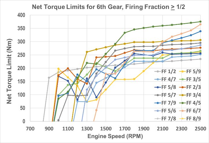
-4-

General Motors’ Dynamic Fuel Management
GM’s History with Active Fuel Management (AFM)
General Motors introduced cylinder deactivation in 2005 on the 5.3L V8 Gen IV Small Block engines
in mid-size utility vehicles under the name ‘Displacement on Demand’. This technology was
subsequently renamed ‘Active Fuel Management’ or ‘AFM’. General Motors has produced millions
of AFM equipped engines with 6 and 8 cylinders, in four engine families, OHV and OHC, in seven
displacements, under 21 unique engine codes, and installed in full size SUV and truck, mid-size
SUV, and small – large sedans and sports cars. GM has over eighty unique patents related to AFM.
All of GM’s current AFM engines can operate in two displacement modes, where a subset of
cylinders has valve deactivation hardware and the same cylinders are deactivated every time. For
V8 engines, such as those in the Chevrolet Camaro and Tahoe four cylinders deactivate. For V6
engines such as those in the Cadillac ATS and CTS, two cylinders deactivate.

GM’s Dynamic Fuel Management (DFM)
GM names this new technology ‘Dynamic Fuel Management’ or DFM to recognize building upon the
foundation of AFM, but to also distinguish it from AFM.
Notable similarities between DFM and AFM are:
    1. Fuel savings are achieved through reduction in pumping losses and improvement in
       thermal efficiency by operating on fewer cylinders at higher cylinder loads.
    2. Operating the engine on the minimum number of active cylinders, each firing at high
       efficiency, that meets engine power requirements and is within vehicle noise and vibration
       (N&V) limits for seamless operation.
    3. Each cylinder’s valve deactivation is accomplished through lost motion switching lifters
       shown in figure 2, each controlled by an electro-hydraulic Oil Control Valves (OCVs).
Notable differences between DFM and AFM are:
   1. DFM requires all cylinders be capable of valve deactivation with AFM lifters and OCVs.
   2. DFM is implemented with up to 29 unique steady state cylinder deactivation patterns or
      modes, called firing fractions, compared to 2 modes for AFM. Firing fraction is the number
      of firing cylinders (numerator) over the number of firing opportunities (denominator). The
      denominator is not limited to the number of engine cylinders. See figure 3.
   3. DFM can have ‘rotating’ cylinder deactivation patterns as well as ‘fixed’ patterns, compared
      to only fixed with AFM. For rotating patterns, which cylinders are being deactivated can
      change with each subsequent engine cycle. See figure 4 for examples or rotating and fixed
      patterns.
   4. DFM firing fraction transitions can be smoother and more efficient by enabling infinitely
      variable firing fractions during transitions between any of the 29 firing fractions.
   5. DFM differs in charge trapping strategy with a low pressure combusted charge trapped in
      deactivated cylinders. DFM requires deactivating and reactivating the intake valve before
      the exhaust valve. AFM traps a full combustion charge by deactivating and reactivating
      exhaust valve before intake valve. Comparison of deactivation sequence in shown in figure
      5.
   6. Using a single OCV per cylinder, the available switching window for successful valve
      deactivation or reactivation with DFM is greatly reduced, requiring faster system response
      with lower variation than AFM. Figure 6 shows the difference in switching windows and their
      locations.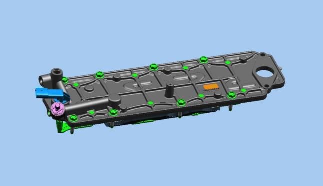
-5-
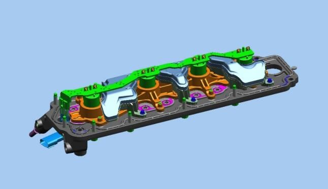
7. For DFM, OCVs are installed directly into the engine block valley, compared to integrated
into the Lifter Oil Manifold Assembly (LOMA) valley cover design for AFM as shown in
figure 7.
8. For DFM, OCVs are energized with peak-hold current drivers for faster response with lower
variation, rather than saturated switch drivers used for AFM engines.
Figure 2: Switching Lifter for AFM and DFM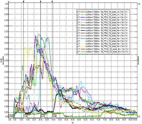
-6-
Firing Fraction to Cylinder Pattern 1 = Cylinder Valvetrain Active
FF 0/8 0 FF 1/9 0.111 FF 1/8 0.125 FF 1/7 0.143 FF 1/6 0.167 FF 1/5 0.200
F/O A B C D E F G H A B C D E F G H A B C D E F G H A B C D E F G H A B C D E F G H A B C D E F G H
Cyl 1 8 7 2 6 5 4 3 1 8 7 2 6 5 4 3 1 8 7 2 6 5 4 3 1 8 7 2 6 5 4 3 1 8 7 2 6 5 4 3 1 8 7 2 6 5 4 3
Cycle 1 0 0 0 0 0 0 0 0 0 0 0 0 0 0 0 0 0 0 0 0 0 0 0 1 0 0 0 0 0 0 1 0 0 0 0 0 0 1 0 0 0 0 0 0 1 0 0 0
Cycle 2 -1 -1 -1 -1 -1 -1 -1 -1 1 0 0 0 0 0 0 0 -1 -1 -1 -1 -1 -1 -1 -1 0 0 0 0 0 1 0 0 0 0 0 1 0 0 0 0 0 1 0 0 0 0 1 0
Cycle 3 -1 -1 -1 -1 -1 -1 -1 -1 0 1 0 0 0 0 0 0 and 7 others -1 -1 -1 0 0 0 0 1 0 0 0 0 1 0 0 0 0 0 1 0 0 0 1 0 0 0 0
Cycle 4 -1 -1 -1 -1 -1 -1 -1 -1 0 0 1 0 0 0 0 0 -1 -1 -1 -1 -1 -1 -1 -1 0 0 0 1 0 0 0 0 or -1 -1 -1 -1 -1 -1 -1 1 0 0 0 0 1 0 0
Cycle 5 -1 -1 -1 -1 -1 -1 -1 -1 0 0 0 1 0 0 0 0 -1 -1 -1 -1 -1 -1 -1 -1 0 0 1 0 0 0 0 0 0 0 0 0 1 0 0 0 0 0 1 0 0 0 0 1
Cycle 6 -1 -1 -1 -1 -1 -1 -1 -1 0 0 0 0 1 0 0 0 -1 -1 -1 -1 -1 -1 -1 -1 0 1 0 0 0 0 0 0 0 0 1 0 0 0 0 0 -1 -1 -1 -1 -1 -1 -1 -1
Cycle 7 -1 -1 -1 -1 -1 -1 -1 -1 0 0 0 0 0 1 0 0 -1 -1 -1 -1 -1 -1 -1 -1 1 0 0 0 0 0 0 1 1 0 0 0 0 0 1 0 -1 -1 -1 -1 -1 -1 -1 -1
Cycle 8 -1 -1 -1 -1 -1 -1 -1 -1 0 0 0 0 0 0 1 0 -1 -1 -1 -1 -1 -1 -1 -1 -1 -1 -1 -1 -1 -1 -1 -1 -1 -1 -1 -1 -1 -1 -1 -1 -1 -1 -1 -1 -1 -1 -1 -1
Cycle 9 -1 -1 -1 -1 -1 -1 -1 -1 0 0 0 0 0 0 0 1 -1 -1 -1 -1 -1 -1 -1 -1 -1 -1 -1 -1 -1 -1 -1 -1 -1 -1 -1 -1 -1 -1 -1 -1 -1 -1 -1 -1 -1 -1 -1 -1
FF 2/9 0.222 FF 1/4 0.250 FF 2/7 0.286 FF 1/3 0.333 FF 3/8 0.375 FF 2/5 0.400
F/O A B C D E F G H A B C D E F G H A B C D E F G H A B C D E F G H A B C D E F G H A B C D E F G H
Cyl 1 8 7 2 6 5 4 3 1 8 7 2 6 5 4 3 1 8 7 2 6 5 4 3 1 8 7 2 6 5 4 3 1 8 7 2 6 5 4 3 1 8 7 2 6 5 4 3
Cycle 1 0 0 0 0 1 0 0 0 0 0 0 1 0 0 0 1 0 0 0 1 0 0 1 0 0 0 1 0 0 1 0 0 1 0 1 0 0 1 0 0 0 0 1 0 1 0 0 1
Cycle 2 1 0 0 0 0 1 0 0 or -1 -1 -1 -1 -1 -1 -1 0 0 1 0 0 1 0 0 1 0 0 1 0 0 1 0 -1 -1 -1 -1 -1 -1 -1 -1 0 1 0 0 1 0 1 0
Cycle 3 0 1 0 0 0 0 1 0 0 0 1 0 0 0 1 0 0 1 0 0 1 0 0 0 0 1 0 0 1 0 0 1 and 7 others -1 -1 -1 0 1 0 1 0 0 1 0
Cycle 4 0 0 1 0 0 0 0 1 or -1 -1 -1 -1 -1 -1 -1 1 0 0 1 0 0 0 1 -1 -1 -1 -1 -1 -1 -1 -1 -1 -1 -1 -1 -1 -1 -1 -1 1 0 0 1 0 1 0 0
Cycle 5 0 0 0 1 0 0 0 0 0 1 0 0 0 1 0 0 0 0 1 0 0 0 1 0 -1 -1 -1 -1 -1 -1 -1 -1 -1 -1 -1 -1 -1 -1 -1 -1 1 0 1 0 0 1 0 1
Cycle 6 1 0 0 0 1 0 0 0 or -1 -1 -1 -1 -1 -1 -1 0 1 0 0 0 1 0 0 -1 -1 -1 -1 -1 -1 -1 -1 -1 -1 -1 -1 -1 -1 -1 -1 -1 -1 -1 -1 -1 -1 -1 -1
Cycle 7 0 1 0 0 0 1 0 0 1 0 0 0 1 0 0 0 1 0 0 0 1 0 0 1 -1 -1 -1 -1 -1 -1 -1 -1 -1 -1 -1 -1 -1 -1 -1 -1 -1 -1 -1 -1 -1 -1 -1 -1
Cycle 8 0 0 1 0 0 0 1 0 -1 -1 -1 -1 -1 -1 -1 -1 -1 -1 -1 -1 -1 -1 -1 -1 -1 -1 -1 -1 -1 -1 -1 -1 -1 -1 -1 -1 -1 -1 -1 -1 -1 -1 -1 -1 -1 -1 -1 -1
Cycle 9 0 0 0 1 0 0 0 1 -1 -1 -1 -1 -1 -1 -1 -1 -1 -1 -1 -1 -1 -1 -1 -1 -1 -1 -1 -1 -1 -1 -1 -1 -1 -1 -1 -1 -1 -1 -1 -1 -1 -1 -1 -1 -1 -1 -1 -1
FF 3/7 0.429 FF 4/9 0.444 FF 1/2 0.500 FF 5/9 0.556 FF 4/7 0.571 FF 3/5 0.600
F/O A B C D E F G H A B C D E F G H A B C D E F G H A B C D E F G H A B C D E F G H A B C D E F G H
Cyl 1 8 7 2 6 5 4 3 1 8 7 2 6 5 4 3 1 8 7 2 6 5 4 3 1 8 7 2 6 5 4 3 1 8 7 2 6 5 4 3 1 8 7 2 6 5 4 3
Cycle 1 0 0 1 0 1 0 1 0 0 0 1 0 1 0 1 0 0 1 0 1 0 1 0 1 0 1 0 1 0 1 0 1 0 1 0 1 0 1 1 0 0 1 0 1 1 0 1 0
Cycle 2 0 1 0 1 0 1 0 0 1 0 0 1 0 1 0 1 or alternately
-1 -1 -1 -1 -1 -1 -1 1 0 1 0 1 0 1 0 1 0 1 0 1 1 0 1 1 1 0 1 0 1 1 0
Cycle 3 1 0 1 0 1 0 0 1 0 1 0 0 1 0 1 0 1 0 1 0 1 0 1 0 1 1 0 1 0 1 0 1 0 1 0 1 1 0 1 0 1 0 1 1 0 1 0 1
Cycle 4 0 1 0 1 0 0 1 0 1 0 1 0 0 1 0 1 -1 -1 -1 -1 -1 -1 -1 -1 0 1 1 0 1 0 1 0 1 0 1 1 0 1 0 1 1 0 1 0 1 1 0 1
Cycle 5 1 0 1 0 0 1 0 1 0 1 0 1 0 0 1 0 -1 -1 -1 -1 -1 -1 -1 -1 1 0 1 1 0 1 0 1 0 1 1 0 1 0 1 0 0 1 1 0 1 0 1 1
Cycle 6 0 1 0 0 1 0 1 0 1 0 1 0 1 0 0 1 -1 -1 -1 -1 -1 -1 -1 -1 0 1 0 1 1 0 1 0 1 1 0 1 0 1 0 1 -1 -1 -1 -1 -1 -1 -1 -1
Cycle 7 1 0 0 1 0 1 0 1 0 1 0 1 0 1 0 0 -1 -1 -1 -1 -1 -1 -1 -1 1 0 1 0 1 1 0 1 1 0 1 0 1 0 1 1 -1 -1 -1 -1 -1 -1 -1 -1
Cycle 8 -1 -1 -1 -1 -1 -1 -1 -1 1 0 1 0 1 0 1 0 -1 -1 -1 -1 -1 -1 -1 -1 0 1 0 1 0 1 1 0 -1 -1 -1 -1 -1 -1 -1 -1 -1 -1 -1 -1 -1 -1 -1 -1
Cycle 9 -1 -1 -1 -1 -1 -1 -1 -1 0 1 0 1 0 1 0 1 -1 -1 -1 -1 -1 -1 -1 -1 1 0 1 0 1 0 1 1 -1 -1 -1 -1 -1 -1 -1 -1 -1 -1 -1 -1 -1 -1 -1 -1
FF 5/8 0.625 FF 2/3 0.667 FF 5/7 0.714 FF 3/4 0.750 FF 7/9 0.778 FF 4/5 0.800
F/O A B C D E F G H A B C D E F G H A B C D E F G H A B C D E F G H A B C D E F G H A B C D E F G H
Cyl 1 8 7 2 6 5 4 3 1 8 7 2 6 5 4 3 1 8 7 2 6 5 4 3 1 8 7 2 6 5 4 3 1 8 7 2 6 5 4 3 1 8 7 2 6 5 4 3
Cycle 1 1 1 0 1 1 0 1 0 0 1 1 0 1 1 0 1 0 1 1 0 1 1 1 0 0 1 1 1 0 1 1 1 0 1 1 1 0 1 1 1 0 1 1 1 1 0 1 1
Cycle 2 -1 -1 -1 -1 -1 -1 -1 -1 1 0 1 1 0 1 1 0 1 1 0 1 1 1 0 1 or -1 -1 -1 -1 -1 -1 -1 1 0 1 1 1 0 1 1 1 1 0 1 1 1 1 0
Cycle 3 and 7 others -1 -1 -1 1 1 0 1 1 0 1 1 1 0 1 1 1 0 1 1 1 0 1 1 1 0 1 1 1 1 0 1 1 1 0 1 1 1 1 1 0 1 1 1
Cycle 4 -1 -1 -1 -1 -1 -1 -1 -1 -1 -1 -1 -1 -1 -1 -1 -1 0 1 1 1 0 1 1 0 or -1 -1 -1 -1 -1 -1 -1 1 1 1 0 1 1 1 0 1 0 1 1 1 1 0 1
Cycle 5 -1 -1 -1 -1 -1 -1 -1 -1 -1 -1 -1 -1 -1 -1 -1 -1 1 1 1 0 1 1 0 1 1 1 0 1 1 1 0 1 1 1 1 1 0 1 1 1 1 1 1 0 1 1 1 1
Cycle 6 -1 -1 -1 -1 -1 -1 -1 -1 -1 -1 -1 -1 -1 -1 -1 -1 1 1 0 1 1 0 1 1 or -1 -1 -1 -1 -1 -1 -1 0 1 1 1 1 0 1 1 -1 -1 -1 -1 -1 -1 -1 -1
Cycle 7 -1 -1 -1 -1 -1 -1 -1 -1 -1 -1 -1 -1 -1 -1 -1 -1 1 0 1 1 0 1 1 1 1 1 1 0 1 1 1 0 1 0 1 1 1 1 0 1 -1 -1 -1 -1 -1 -1 -1 -1
Cycle 8 -1 -1 -1 -1 -1 -1 -1 -1 -1 -1 -1 -1 -1 -1 -1 -1 -1 -1 -1 -1 -1 -1 -1 -1 -1 -1 -1 -1 -1 -1 -1 -1 1 1 0 1 1 1 1 0 -1 -1 -1 -1 -1 -1 -1 -1
Cycle 9 -1 -1 -1 -1 -1 -1 -1 -1 -1 -1 -1 -1 -1 -1 -1 -1 -1 -1 -1 -1 -1 -1 -1 -1 -1 -1 -1 -1 -1 -1 -1 -1 1 1 1 0 1 1 1 1 -1 -1 -1 -1 -1 -1 -1 -1
FF 5/6 0.833 FF 6/7 0.857 FF 7/8 0.875 FF 8/9 0.889 FF 1/1 1.00
F/O A B C D E F G H A B C D E F G H A B C D E F G H A B C D E F G H A B C D E F G H
Cyl 1 8 7 2 6 5 4 3 1 8 7 2 6 5 4 3 1 8 7 2 6 5 4 3 1 8 7 2 6 5 4 3 1 8 7 2 6 5 4 3
Cycle 1 0 1 1 1 1 1 0 1 0 1 1 1 1 1 1 0 0 1 1 1 1 1 1 1 0 1 1 1 1 1 1 1 1 1 1 1 1 1 1 1
Cycle 2 1 1 1 1 0 1 1 1 1 1 1 1 1 1 0 1 -1 -1 -1 -1 -1 -1 -1 -1 1 0 1 1 1 1 1 1 -1 -1 -1 -1 -1 -1 -1 -1
Cycle 3 1 1 0 1 1 1 1 1 1 1 1 1 1 0 1 1 and 7 others -1 -1 -1 1 1 0 1 1 1 1 1 -1 -1 -1 -1 -1 -1 -1 -1
Cycle 4 -1 -1 -1 -1 -1 -1 -1 -1 1 1 1 1 0 1 1 1 -1 -1 -1 -1 -1 -1 -1 -1 1 1 1 0 1 1 1 1 -1 -1 -1 -1 -1 -1 -1 -1
Cycle 5 1 0 1 1 1 1 1 0 1 1 1 0 1 1 1 1 -1 -1 -1 -1 -1 -1 -1 -1 1 1 1 1 0 1 1 1 -1 -1 -1 -1 -1 -1 -1 -1
Cycle 6 1 1 1 1 1 0 1 1 1 1 0 1 1 1 1 1 -1 -1 -1 -1 -1 -1 -1 -1 1 1 1 1 1 0 1 1 -1 -1 -1 -1 -1 -1 -1 -1
Cycle 7 1 1 1 0 1 1 1 1 1 0 1 1 1 1 1 1 -1 -1 -1 -1 -1 -1 -1 -1 1 1 1 1 1 1 0 1 -1 -1 -1 -1 -1 -1 -1 -1
Cycle 8 -1 -1 -1 -1 -1 -1 -1 -1 -1 -1 -1 -1 -1 -1 -1 -1 -1 -1 -1 -1 -1 -1 -1 -1 1 1 1 1 1 1 1 0 -1 -1 -1 -1 -1 -1 -1 -1
Cycle 9 -1 -1 -1 -1 -1 -1 -1 -1 -1 -1 -1 -1 -1 -1 -1 -1 -1 -1 -1 -1 -1 -1 -1 -1 1 1 1 1 1 1 1 1 -1 -1 -1 -1 -1 -1 -1 -1
Figure 3: 29 DFM Cylinder Deactivation Patterns. Each row shows one engine cycle or two crank revolutions and the
number of rows indicate the number of engine cycles required to complete the pattern. Fixed patterns show the
alternative cylinder deactivation patterns available for that firing fraction.
Note that even though a large number of firing fractions are available, these sequences are only
achieved in steady state conditions, which are infrequent during the drive cycle. On the US FTP City
cycle, the average time in a given firing and skipping sequence was 2 seconds before transitioning
to the next sequence. As such the transitioning strategy between firing fractions is critical and is a
key part of the intellectual property behind DFM and the fuel consumptions gains intrinsic to DFM.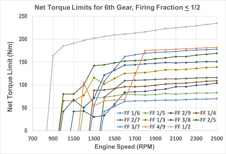
-7-

   Firing Fraction 1/3                             1 = Firing                   Firing Fraction 1/2
     A           B       C       D       E           F       G         H             A    B           C   D           E       F       G       H
     1           8       7       2       6           5       4         3             1    8           7   2           6       5       4       3
             0       0       1       0         0         1         0       0          0      1      0          1          0       1       0       1
             1       0       0       1         0         0         1       0    or alternative pattern
             0       1       0       0         1         0         0       1          1      0      1          0          1       0       1       0

  Rotating Deactivation Pattern Example, 1/3rd Firing                           Fixed Pattern Example, ½ Firing Fraction. 4 cylinders
  Fraction. 1 cylinder active out of 3 firing opportunities.                    active out of 8 firing opportunities (V8 AFM). The
  The full pattern repeats every 3 engine cycles.                               same cylinders are active every engine cycle.

                                             Figure 4: Rotating and Fixed Pattern Examples

 Figure 5: Deactivation Sequence Comparison – Solid lines for active valves and dashed lines for deactivated valves

 14.00
                                                         Switching Window Comparison

 12.00

 10.00                                                                     Exh Lift Act
                                                                           Int Lift Act
  8.00

  6.00

  4.00
                                                    Switching Window AFM                           DFM
  2.00                                                 480 Deg Crank                           240 Deg Crank

  0.00
         0               180             360                 540               720              900            1080           1260            1440
                                                                   Running Crank Angle, TDCC
Figure 6: Comparison of AFM and DFM Switching Window where oil pressure changes and lifter latching pins change
                                    states before the next valve event.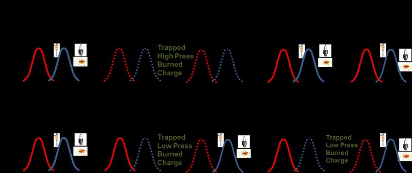
-8-

                                             Oil Control Valve
                                                   1 of 8

                                                                                                          Oil Control Valve
                                                                                                                1 of 4

DFM Oil Control Valves in Engine Block                           AFM Oil Control Valves in LOMA / Valley Cover
                                 Figure 7: Oil Control Valves Comparison of DFM and AFM

Dynamic Fuel Management Development
The project was initiated as an Advanced Technology Work Project, led by Global Propulsion
Systems Advanced Controls Engineering with support of propulsion systems and vehicle
engineering and analysis groups, including engineering technical specialists for every system and
component identified as potentially affected.

Fuel Economy Prediction
One of the earliest tasks was to predict the potential fuel economy improvement before committing
to hardware and controls development. Using existing AFM engine data, a virtual engine was
modeled to predict available engine torque and fuel rates for each firing fraction. This virtual engine
was integrated into GM’s proprietary fuel economy prediction tools, making an initial prediction of up
to 9 percent FTP fuel economy improvement (theoretical) on top of the improvement already
achieved with AFM in full-size trucks. The initial prediction assumed no noise and vibration
limitations. The project development fuel economy target was adjusted for anticipated torque limit
reductions and the increased torque converter slip required to meet noise and vibration requirements
and for any expected losses during firing fraction transitions. As the project proceeded to hardware
testing, the virtual engine was updated with engine test data and the initial torque limits by firing
fraction were updated based on vehicle test data.

Requirements and Targets
Subset of requirements and targets selected early in the development process that must be met:
    1.   Significant fuel economy improvement over full-size trucks with AFM
    2.   Cost effective grams/mile CO2 improvement
    3.   US FTP ULEV 50 Emissions
    4.   Objective and subjective drive quality at proprietary GM benchmark
    5.   Noise and vibration at a proprietary GM benchmark
-9-
6. Durability of deactivation system for tens of millions of cycles at a proprietary GM
benchmark
Potential Risks
Based on unique DFM behaviors and anticipated changes required to implement DFM, engineering
teams identified potential hardware and control system risks that must be analyzed, tested, and
eliminated or mitigated included:
1. Potential valvetrain damage from mistimed deactivation events
2. Deactivation system durability with high frequency switching
3. Accessory drive durability
4. Crank damper / timing chain drive durability
5. Lubrication and ventilation systems potentially negatively affected
6. Torque converter clutch / isolator durability
7. Air estimation accuracy within limits for precise air/fuel control
8. Cam phaser control accuracy within limits
9. Torque estimation and control, steady state within limits
10. Torque converter slip controllability for isolation
Engine Hardware
Valvetrain Deactivation System
With the charge trapping strategy change for DFM and increase in number of deactivation events
with rotating fractions, the valve deactivation system design and validation was an area of significant
effort. Mistimed deactivation or reactivation events can cause increased emissions and fuel
consumption, misfires, and possible valvetrain damage.
The first development engines included AFM lifters on all cylinders and sixteen oil control valves
(OCVs) integrated into the valley cover, similar to AFM. Unlike AFM, the first DFM development
engines used two OCVs per cylinder, one for each exhaust and intake, rather than one per cylinder
like AFM. This provided large switching windows and allowed use of AFM style OCVs driven by a
slightly modified engine control module. These engines performed well for early engine dyno and
vehicle development.
The single OCV per cylinder design was determined to be the optimal solution for packaging, cost,
diagnostics, and potential failure modes. OCV response time is defined as the time from voltage
change at the OCV to a pressure threshold. Total system response is from voltage change at the
OCV to lifter latching movement to the desired state. The single OCV design increases the required
prediction accuracy and greatly reduces the allowable variation in response times.
Potential suppliers for components and systems participated in workshops allowing the production
suppliers for lifters, OCVs, and engine controller to be selected very early in the procurement
process. This lead to close cooperation in finalizing system and component requirements, designing
the system and components, and validation testing to meet the more demanding technical
requirements of DFM.
GM’s proprietary hydraulic system models and Design for Six Sigma (DFSS) processes led to
selection of the optimal OCV location and oil passage dimension in the engine block. GM’s OCV
supplier created high fidelity OCV models for their internal development and for GM engine controller
development. GM’s Signal Delivery Subsystem (SDSS) process was used to identify and quantify
sources of variation of the OCV driver system, OCV, lifter, hydraulic system, and engine controller
inputs and outputs to develop a robust system.- 10 -
In addition to analysis, a variety of test fixtures and engines were built to quantify system response
over all expected operating conditions of engine speed, oil temperature, oil pressure, oil aeration, oil
viscosity, and oil quality. Transparent fixtures were used to visualize oil and air flow around the OCV
and within control port passage between OCV and lifter. Single OCV static test fixtures were used
by suppliers for OCV and lifter development. Other single cylinder fixtures included rotating cam
lobes and moving lifters to capture dynamic conditions. Non-firing engine, or motoring fixtures were
used to test the complete engine hydraulic and deactivation system to identify system issues,
determine switching window angles, map OCV and system response performance, and quantify
variation with limit specification parts. Firing engines completed the verification and validation
process in engine dyno and in vehicles. All the fixtures included oil pressure sensors in the control
ports for response time measurement. Dynamic fixtures and early firing engines included valve lift
sensors to check successful performance for each deactivation and reactivation event. Figure 8
shows typical warmed up OCV response time from voltage to oil pressure threshold are less than 3
msec for both deactivation and reactivation of a cylinder.
Deactivation Event Reactivation Event
OCV Voltage
OCV Current
2.1 msec
Control Port Response
Pressue
2.4 msec
Response
Figure 8: Deactivation System Response from Voltage Change to Oil Pressure Threshold
Accessory Drive
For the same engine torque, running in lower firing fractions requires higher individual cylinder
torques, which increases tensioner arm displacement and amplitudes, belt flutter, and the potential
for higher belt slip. GM and accessory drive suppliers jointly analyzed and tested each firing fractions
across a range of accessory loads throughout the DFM engine speed range. Higher belt slip was
measured at some engine speeds and firing fractions, but are within design limits and no changes
to the accessory drive system are required and no limits are placed on firing fraction operation.
Crankshaft Damper
Crankshaft damper modes were identified as a potential issue due to new excitation frequencies with
DFM. Analysis and testing determined torsional vibrations are within limits for all firing fractions and
concluded that no hardware changes or firing fraction limits are required.
Camshaft / Timing Chain / Cam Phaser
The engine camshaft was changed to have deactivation lobe profiles for all valves, which differ in
the initial ramp to account for lash differences with deactivating lifters. Deactivating cylinders also
affect cam torque. Analysis and testing showed a small, but acceptable increase in displacement of
the chain tensioner and a small, but acceptable increase in cam phasing position error for lower firing
fractions with DFM.- 11 -
Lubrication and Ventilation Systems
Engine oil lubrication pressures, oil contamination, oil aeration, and crank case pressure analysis
and testing confirmed all metrics are within limits for all firing fractions and no hardware changes or
firing fraction limitations are required.
Transmission and Isolation Hardware
The torque converter design changes and increased slip are necessary for N&V isolation for AFM in
steady state firing fractions and transitions between firing fractions. DFM increases the importance
of the torque converter isolation when fewer cylinders are firing at higher cylinder loads. In general,
higher converter slip improves isolation for low firing fractions, but at a cost to fuel economy and the
risk of fluid damage and excessive clutch wear. The goal is to control transmission output torsional
vibrations to acceptable levels with a minimum of slip. Working with suppliers, vehicle data and
analysis, an advanced converter with long travel, dual plate clutch, and Centrifugal Pendulum
Absorber (CPA) was selected. The CPA is tuned to second order (1/2 Firing Fraction or V4), which
has high usage in DFM. Torque converter slip is limited at higher engine torques to avoid
overheating of the clutch and these limits are considered in selection of firing fractions. Figure 9
illustrates the effectiveness of isolation from the torque converter to reduce torsional vibrations. No
other transmission hardware changes are required with DFM compared to AFM.
TCC Locked TCC w/ 80 rpm commanded slip
Torsional Vibration at Transmission Output
Torsional Vibration at Transmission Output
0.5 0.5
DFM
(rad/s)
(rad/s)
AFM V4
0.0 0.0
0.0 100.0 0.0 100.0
Frequency Hz V8 mode Frequency Hz
Figure 9: Comparison of transmission output torsional vibration for DFM with locked and slipping torque converters.
Noise and Vibration (N&V)
For V8 engines with AFM, N&V requirements and analysis are primarily focused on two engine
orders, expecting excitations to be only fourth order (V8) and second order (V4). In general, DFM
firing fractions below V4 and lower engine speeds provide the greatest challenges for N&V. Analysis
methods and mitigation strategies were expanded to include the lowest order driven by firing fraction
denominator and its higher harmonics to better comprehend the full effects of 29 firing fractions.
Extending existing AFM math and hardware based tools and post processing methods for the new
DFM orders required significant effort.
DFM also required extensive modification of existing proprietary driveline models to simulate high
fidelity engine torque signatures for every firing fraction. The driveline model includes engine torque,
torque converter, transmissions, driveline and isolators. This model is used for analysis and tuning
of torque converters, driveline components, and driveline isolators to predict the firing fraction effects
on torsional output vibration for driveline induced N&V. Engine models for exhaust and induction
noise were updated to allow running steady state for any firing fraction.- 12 -
The N&V vehicle specifications for AFM and DFM primarily include seat track vibration, steering
wheel vibration, and interior noise. To verify and update specifications for DFM, smooth road testing
identified road noise baselines for road masking and a vehicle clinic was conducted to characterize
human subjective ratings of perceptible vehicle vibrations with DFM. It was necessary to base the
vibration specifications for DFM on human perceptible levels because the excitation frequencies with
DFM are significantly below those encountered in conventional propulsion vehicles and occur in a
range where humans experience the highest sensitivity to vibration.
N&V testing in a hemi-anechoic vehicle dynamometer cell was key in DFM development. Testing
included engine speed sweeps for each firing fraction across a set of gears, engine torques, and
torque converter slip settings. This data was processed against the vehicle technical specifications
to set initial torque slip targets and torque limits for acceptable N&V for each firing fraction by gear
and engine speed. Road testing results at the initially identified limits led to refining the torque limits
and slip targets for future vehicle dyno mapping. Further analysis identified opportunities to reduce
the dyno test time with continuous improvement in analytical tools for prediction of limits with less
data. Figure 10 shows example torque limits developed for 6th gear and how these torque limits
may need to be reduced over narrow engine speeds where specific firing fractions can excite vehicle
modes.
Figure 10: Net Torque Limits for 6th Gear
Vehicle Integration Results
Vehicle testing was executed to understand and address DFM broadband driveline path, exhaust
and air induction sources. With DFM, no changes were required to engine, transmission, or body
mount systems. Steering column vibration was reduced through changes in the mounting structure
and integration of an absorber in the steering wheel. Torque converter testing identified design
improvements to reduce DFM induced vibrations. Exhaust system testing resulted in volume
changes and selection of a single passive valve located on the muffler for the 5.3L engine. Variable
air inlet valve testing identified opportunities for minor improvements in induction source noise
attenuation. Finally, installing a torsional vibration absorber on the driveshaft demonstrated
cancellation of torsional vibrations over a narrow frequency.
Engine Controls
Engine Controller Hardware
DFM is supported in GM’s fourth generation E90 engine control module, requiring only the addition
of eight current peak-hold drivers for faster OCV response and an oil temperature sensor for more
accurate response prediction.- 13 - Firing Fraction Selection Algorithm Selection of the correct firing fraction is necessary for optimal fuel economy, N&V, and drive quality. The frequency of beneficial firing fraction changes must also be balanced against the small firing fraction transition losses during these changes. For AFM, cylinder deactivation is enabled based on indicated torque requirement, using the lower of N&V torque limits and equivalent fuel consumption torque, compared to all-cylinder mode. DFM uses a similar approach by selecting the N&V viable firing fraction with the lowest fuel rate for the requested torque and expected engine speed. Hysteresis pairs on engine torque request, engine speed, and relative efficiency prevent busyness from undesirable frequent firing fraction changes that would result in little or no benefit. Air Estimation Algorithm Accurate air estimation is required under all conditions for emissions, fuel economy, and smooth torque delivery. For AFM, air estimation uses a mass airflow meter for steady state conditions and volumetric efficiency calculations for transient conditions where one set of coefficients used for all cylinder mode and another for deactivation mode. Air estimation algorithm development for DFM started before the first DFM engines were running. Early development relied on co-simulation of control algorithm and engine models for engine air. The engine model was modified to support individual cylinder deactivation, allowing simulation of any firing fraction in steady state and transient conditions. The engine model was refined as firing engine data became available from dyno mapping. The final solution is similar to the algorithm for AFM, except using a single base all-cylinder volumetric efficiency (VE) calculation with VE offsets for each firing fraction. Torque Estimation and Control Algorithms Accurate torque estimation and control is required for drive quality, smooth transmission shifting, and smooth firing fraction transitions. AFM uses two invertible multi-term torque models, one for all cylinders and one for cylinder deactivation, with terms for actuator positions and sensor readings. DFM uses a similar strategy, but with a single all-cylinder multi-term model where firing fraction is added as a new term. Firing Fraction Transitioning Algorithms Changing firing fraction can require torque smoothing for good drive quality. With AFM, transition from all cylinders to deactivated cylinders starts by pre-positioning the camshaft phasing while increasing torque converter slip and then finishes by coordinating throttle opening changes while stepping to deactivating cylinders in one engine cycle. DFM improves on this strategy, with the better matching of air during firing fraction reductions, through improved coordination of throttle movement with decreases of firing fraction in smaller steps over many engine cycles, resulting in smoother transitions. With AFM, transitions to all cylinders is performed by stepping the throttle to the all-cylinder position and activating all deactivated cylinders in one engine cycle, requiring spark retard to smooth the unavoidable torque increase as cylinders are activated faster than intake manifold pressure can decrease. DFM improves on this strategy for firing fraction increases by coordinating throttle movement with increases of firing fraction in smaller steps over many engine cycles to better match intake manifold pressure decreases, minimizing losses by greatly reducing or eliminating the need for spark retard. Fuel, Spark, and Cam Phaser Control Algorithms For AFM, fuel, spark, and cam phaser position are based on predicted air per cylinder, with separate calibration tables available for all cylinder and deactivated modes. This same capability was retained for DFM with the AFM deactivated mode tables covering all firing fractions less than 1 (V8) for fuel and cam phaser. All firing fractions use the same spark calibration tables.
- 14 -

Diagnostics
Of all the diagnostics required for OBD, only a few require major changes for DFM. Fail-to-deactivate
cylinders for AFM strategy would not support DFM with its high frequency cylinder deactivations and
re-activations. A new crank speed / intake manifold pressure failure-to-deactivate diagnostic was
developed to enable diagnostics for every firing fraction in steady state and transient conditions.
Both AFM and DFM use cylinder misfire diagnostics for failure-to-reactivate. AFM misfire is based
on changes in crankshaft speed, with separate calibrations for all activated and deactivated cylinder
modes. Misfire detection algorithm for DFM introduces a new crankshaft position based strategy.
DFM also adds a new diagnostic for valvetrain protection that detects trapping of an undesired high-
pressure charge that could damage intake valves, pushrods, or lifters if an intake valve were re-
activated with high pressure trapped in the cylinder. This new diagnostic is based on crankshaft
speed variations and includes remedial actions to purge the cylinder charge before reactivating the
intake valve when a fault is detected.

Transmission Controls
AFM relies on close communication between engine and transmissions controllers to coordinate
transitions to and from deactivated cylinder modes. This interface was expanded for DFM to include
firing fractions for selecting torque converter clutch (TCC) slip targets. AFM uses separate slip target
calibration sets for all cylinder and cylinder deactivation modes. Adding separate TCC slip target
calibrations for each firing fraction and gear combination would greatly increase calibration space
and complexity for DFM. The solution was to add a limited number of TCC slip target calibration
alternatives for each gear, assignable by firing fractions.
Through a separate ATW project, new slip control algorithms were developed to improve upon AFM
TCC slip control response time and control accuracy. This provided improved efficiency, drive
quality, and N&V performance with DFM.

DFM Development Project Results

Noise and Vibration
DFM N&V understanding, tools, methods, and performance consistently improved over the period
of the ATW project. Learning from regular on-road testing and demonstrations let to refinements in
objective target levels for acceptable N&V.

Drive Quality
DFM drive quality also consistently improved over the ATW project. Periodic testing with
standardized maneuvers was used to identify any objective drive quality issues. Engineers and
testers also captured subjective comments during standardized maneuvers and general driving. All
these issues were documented, tracked and addressed with software improvements and calibration
refinements. The main DFM issues were related to firing fraction transitions, tip-in response delay,
transitions during gear shifts, small torque bumps, and small acceleration overshoot. At the end of
development, objective metrics for DFM were comparable to production AFM vehicles.

Durability
Two main areas of concern for DFM were tested. The deactivation OCVs and lifters demonstrated
durability over the required millions of cycles on non-firing and firing engines. Torque converter
- 15 -

clutch energy was predicted to be well below targets, based on extrapolation of total lifetime energy
from durability driving schedules.

Controls and Diagnostics
Engine and transmission control systems met requirements by demonstrating fuel economy,
emissions, N&V, and drive quality for DFM. Added software and calibrations fit within controller
capabilities for memory and processing. Diagnostics development and testing demonstrated
successful calibration of limited areas to provide sufficient confidence for production implementation.

Risk
All the potential DFM risk issues were either eliminated or mitigated with new strategies developed
through analysis and testing of hardware.

Fuel Economy and Emissions
The ATW project achieved significant improvement in fuel economy over the FTP cycle. The EPA
urban driving schedule identifies four modes of operation, Idle, Accel, Cruise, and Decel. As
illustrated in figure 11, compared to an AFM baseline test, DFM further reduces fuel consumption in
Accel, Cruise, and Decel. Approximately 27 percent of the improvement is in acceleration where
DFM can operate at firing fractions between 1/2 and 1, where AFM engines can only operate on all
cylinders. Approximately 36 percent of the fuel economy improvement is in cruise areas where
firing fractions below 1/2 are generally alternatives to V4 for AFM. Significantly, DFM also improves
fuel economy by approximately 37% in decel conditions where the lowest firing fractions can greatly
reduce pumping losses, which reduces engine braking, enabling increases in decel fuel cut-off
(DFCO) times by over 30 percent. Firing fraction of 0, also called decel cylinder cut off (DCCO),
where all cylinders are deactivated, has an added benefit by eliminating post DFCO enrichment for
catalytic converter oxygen storage. There are no fuel efficiency improvements in idle operation as
both AFM and DFM idle with all cylinders active for N&V. Figure 11 also shows the percentage of
firing fraction usage on FTP City, Highway and US06 tests. DFM also successfully demonstrated
US emissions with aged converters to internal targets relative to ULEV50 (0.050 g/mi NMOG+NOx
on the US FTP City / Highway test).

                             Figure 11: Firing Fraction Usage on US FTP Tests
- 16 -
Intellectual Property
From the start of joint development to today, a number of improvement opportunities have been
identified. GM contributed to 6 patent applications to improve Tula’s original DSF.
GM Dynamic Fuel Management Roadmap
2018: First production of 5.3L and 6.2L V8 DFM engines in Silverado and Sierra full size trucks
Future Years. The potential exists for further improvements in DFM fuel economy benefits, including;
1. Introduction of DCCO, all cylinder deactivation
2. Continued development of controls and calibrations to further improve DFM fuel economy
3. Development of advanced driveline and vehicle components and systems to further
mitigate DFM induced N&V for improvement in fuel economy
4. Expand application of V8 DFM engines to other vehicles
Future Developments in Dynamic Skip Fire
In addition to the improvements possible to Dynamic Fuel Management in the immediate future, a
number of future technologies are being developed by Tula to optimize cylinder deactivation in
hybrid, Miller-cycle, lean/diesel engines, and autonomous vehicles. In this section, eDSF and mDSF
are discussed, which couple DSF with electrified powertrains and miller-cycle engines respectively.
eDSFTM: Coupling DSF with Vehicle Electrification
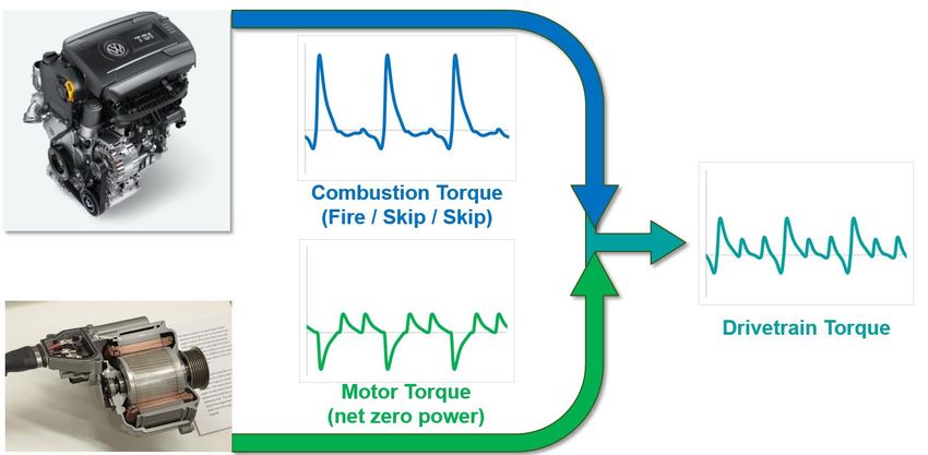
In order to meet future fuel consumption requirements, Tula has created the concept of eDSF. eDSF
expands the range of operation of DSF by using an electric machine out of phase with the torque
pulsations of a combustion engine. The concept is shown in Figure 12.
Figure 12: Dynamometer experiments have been conducted to show proof of concept with a ‘P0‘ electric machine
coupled to the crankshaft via a belt. One example result is shown in Figure 13. In this example, using a time-averaged
0.7 kW of oscillating torque is able to reduce the 21 Hz pulsation by over 70%.
Tula has developed a demonstration vehicle based on a 1.8L GTDI C-segment vehicle [5]. The
technology requirements for this operation are mildly incremental to current 48V systems currently
going into production. These changes are needed to assure production of torque in the relevant
frequency ranges with high roundtrip efficiency, and include- 17 -
• High efficiency motor-generator unit (MGU) inverter-integrated efficiency. This usually
entails precise magnetic design of the motor for low iron and copper losses, and properly
configured field-oriented control or other modern motor control method that achieves precise
control of torque while at the same time maintaining efficiency.
• Adjustments to inverter software to ensure moderate bandwidth torque frequency response
on the order of 40Hz
• Battery system with high roundtrip efficiency, or addition of moderate capacitance to the DC
bus along with power switching circuitry to direct power to the capacitor and/or battery in
synch with the MGU torques
• Optimization of the front-end accessory drive tensioner to maintain belt-pulley contact under
reversing MGU torques
Tula has simulated using this technology on drive cycles, using the same VW 1.8L Jetta described
earlier in this work. Using dynamometer experiments to define fuel consumption maps, it was
possible to estimate the vehicle-level CO2 reduction using this technology. This technology is
expected to gain an additional 3% on the US CAFE or NEDC cycles, for a total reduction of CO 2 of
approximately 11% as shown in Figure 14.
Figure 13: Dynamometer Experimental Results of eDSF
Figure 14: CO2 Reduction Potential of eDSF Strategy- 18 -
mDSFTM: Coupling DSF with Miller Cycle Engines
Separately from improvements made possible by DSF, the automotive industry has also embraced
thermodynamic improvements made possible by ‘Miller‘ cycle engines, achieved through a
combination of early intake valve closing (EIVC), higher compression ratios, moderate displacement
increases and intake air boosting. These improvements are often on the order of 3-4%, resulting
from reduced pumping losses and increased expansion work. However, Miller cycle engines require
compromises between maximum power and efficiency, as the EIVC strategy effectively limits the
amount of airflow through the engine. To maintain the full dynamic range of engine operation,
variable intake valve lift systems are often employed. In a 2-step Miller engine, a low-power and a
high-power configuration are available, which switch at specified speed-load points to maximize part-
load efficiency and deliver the target peak torque. Even so, best fuel efficiency of the low power
Miller configuration is typically sacrificed in exchange for extended operating range, which can
improve real-world fuel consumption and minimize mode switches.
The mDSF strategy leverages the advantages of both Miller cycle engines and dynamic skip fire.
The combination addresses both the NVH constraints and efficiency-power tradeoffs that limit the
fuel efficiency improvement potential of standard DSF and Miller cycle engines. In mDSF, individual
cylinders operate at three possible states: high charge firing (high cylinder load), low charge firing
(low cylinder load) and deactivation. The state for each cylinder is dynamically selected on a cycle-
by-cycle basis to deliver the requested engine torque at maximum efficiency. Figure 15 shows one
possible mDSF firing history for a 4-cylinder engine (bottom-left panel) as a function of driver torque
demand relative to maximum engine torque (top-left panel). Although several implementation
strategies are feasible, the most cost-effective valvetrain only requires independent control of the
two intake valves. This can be accomplished with only one additional oil control valve per cylinder.
Figure 15 (right panel) illustrates the three valve actuation states for high charge fire, low charge fire
and deactivation or skip, where the low charge fire state is achieved using an aggressive Miller cycle
implementation. Compared to standard DSF with only two cylinder states (firing and deactivation),
mDSF provides finer control over the firing frequency, torque waveform and resulting NVH
characteristics. Furthermore, mDSF allows full optimization of the Miller cycle and effectively
eliminates the efficiency-power tradeoff.
Figure 15: mDSF Concept – Firing History and Valvetrain Implementation- 19 -
Figure 16: mDSF Efficiency and Firing Characteristics
Status of Tula experiments and projections are reflected in Figure 16, which show a 17% fuel
consumption reduction at 30 N-m and 1500 RPM (left panel). High load testing revealed a potential
reduction in maximum torque of up to 10% throughout the load range due to the asymmetric valve
lifts, where low-speed torque was limited by increased knock tendency and high-speed torque was
limited by airflow restriction. This negative impact could be mitigated by further optimization of the
combustion and boosting systems. Currently, it is assumed vehicle performance can be held
constant for the Miller and mDSF strategies through a modest displacement increase to 2.1L from
2.0L. Figure 16 (right panel) also shows the firing fraction and high fraction selection for best
efficiency in 2000 rpm, 3rd gear, where the high fraction variation illustrates mDSF’s added capability
for dynamic switching between high and low charge. Overall vehicle fuel consumption improvement
is shown in Figure 17. The mDSF technology shows dramatic improvements over the already
efficient 2-Step Miller engine, ranging from 6% to 8% depending on drive cycle. At an estimated
OEM on-cost of less than 400€, the mDSF technology presents the best value of any technology in
the market today.
Figure 17: CO2 Reduction Potential of mDSF Strategy- 20 -
Conclusions
Tula and General Motors have worked together to successfully introduce Dynamic Fuel Management
commercially. DFM has been successfully demonstrated as a novel extension of AFM to further
reduce fuel consumption while meeting GM durability, noise, vibration and drive quality
requirements. DFM was approved for integration in the model year 2019 control systems and
hardware for the new generation of full size V8 truck engines. This first application will not include
DCCO. The new Silverado and Sierra will also benefit from improvements in drive quality and other
fuel saving technologies. Final fuel economy numbers will be released later in 2018.
Furthermore, improvements to Tula’s Dynamic Skip Fire are ongoing. The first two technologies
slated to be introduced are eDSF and mDSF, which introduced optimized cylinder deactivation to
hybrid vehicles and Miller-cycle engines respectively. Gains of 7-11% over baseline are made
possible by these technologies. These optimized technologies are available to OEM’s for a total on-
cost of around 400€, which makes them the best value in fuel consumption commercially available.
References
1. Serrano, J., Routledge, G., Lo, N., Shost, M. et al., "Methods of Evaluating and Mitigating NVH when Operating an
Engine in Dynamic Skip Fire," SAE Int. J. Engines 7(3):1489-1501, 2014, doi:10.4271/2014-01-1675.
2. Chen, S., Chien, L., Nagashima, M., Van Ess, J. et al., "Misfire Detection in a Dynamic Skip Fire Engine," SAE Int. J.
Engines 8(2):389-398, 2015, doi:10.4271/2015-01-0210.
3. Chien, L., Younkins, M., and Wilcutts, M., "Modeling and Simulation of Airflow Dynamics in a Dynamic Skip Fire
Engine," SAE Technical Paper 2015-01-1717, 2015, doi:10.4271/2015-01-1717.
4. Wilcutts, M., Switkes, J., Shost, M., and Tripathi, A., "Design and Benefits of Dynamic Skip Fire Strategies for Cylinder
Deactivated Engines," SAE Int. J. Engines 6(1):278-288, 2013, doi:10.4271/2013-01-0359.
5. Wilcutts, M., Nagashima, M., Eisazadeh-Far, K., Younkins, M. and Confer, K., “Electrified Dynamic Skip Fire (eDSF):
Design and Benefits”, SAE paper 2018-01-0864, 2018.
6. Ortiz-Soto, E. and Younkins, M., “mDSF: Uncompromised Engine Fuel Efficiency and Performance Via DSF and
Miller Cycle Synergies,” SAE WCX 2018 Presentation (18PFL-0700), 2018
7. “Cost, Effectiveness and Deployment of Fuel Economy Technologies for Light-Duty Vehicles” by the National
Research Council – The National Academies Press – April 2015.
8. "U.S. Energy Information Administration - EIA - Independent Statistics and Analysis." International Energy Statistics.
N.p., n.d. Web. 15 Jan. 2017.
9. Displacement on Demand for Improved Fuel Economy without Compromising Performance on GM’s High Value
Engines, Powertrain International Winter 2004
10. Displacement on Demand: Tomorrow’s Propulsion System with Cylinder Deactivation, MTZ extra October 200539t
hI nt
ernat
ionalVi
ennaMot
orSymposi
um
Apri
l2018
Formoreinfor
mat ion,pl
easevi
sit
:
www.gm.com
www.tul
atech.comYou can also read