Efficient Energy Automation with the IEC 61850 Standard Application Examples - Energy Automation
←
→
Page content transcription
If your browser does not render page correctly, please read the page content below
Efficient Energy Automation
with the IEC 61850 Standard
Application Examples
Energy Automation

Answers for energy.

Editorial

              Efficient Energy Automation
              with the IEC 61850 Standard

              The IEC 61850 standard has been defined in cooperation with manufactu-
              rers and users to create a uniform, future-proof basis for the protection,
LSP2870.eps

              communication and control of substations. In this brochure, we present
              some application examples and implemented stations with the new
              IEC 61850 communication standard. IEC 61850 already has an excellent
              track record as the established communication standard on the worldwide
              market for the automation of substations.
              Its chief advantages are:
              § Simple substation structure: No more interface problems.
                 With IEC 61850, protocol diversity and integration problems are a thing
                 of the past.
              § Everything is simpler: From engineering to implementation, from ope-
                 ration to service. Save time and costs on configuration, commissioning
LSP2871.eps

                 and maintenance.
              § Reduction of costs: IEC 61850 replaces wiring between feeders, control
                 switches, and signaling devices.
              § More reliability: You only use one communication channel for all data –
                 in real time, synchronized via Ethernet.
LSP2872.eps

              Why use IEC 61850 technology from Siemens?
              Siemens is the global market leader in this area. For you, that means:
              You benefit from the experience of projects for more than 1000 substa-
              tions and 140000 protection devices implemented in accordance with the
              IEC 61850 communication standard by the end of 2010. Siemens offers
              you IEC 61850 technology that is certified as Class A by the independent
              testing laboratory KEMA. Future-proof investment due to convincing
              migration concepts: SIPROTEC 4 protection devices manufactured since
              1998 can be upgraded to make them IEC 61850-compatible without any
              problem. The solutions from the SICAM 1703 and SICAM PAS product lines
              offer you flexible configurations for seamlessly integrating the latest
              IEC 61850 concepts into existing substations.
              While reading this brochure, discover the diverse efficiency potential of
              energy automation with the IEC 61850 worldwide communication standard.
              Choose a Powerful Partnership
              Energy Automation from Siemens

              Ingo Erkens
              General Manager
              Energy Sector
              Power Distribution Division
              Energy Automation Products
Efficient Energy Automation
with the IEC 61850 Standard
Application Examples        Content                       Page

                             Switchgear Interlocking
                             with IEC 61850-GOOSE         3
                             Reverse Interlocking Using
                             the GOOSE of IEC 61850       7
                             Beneficial Engineering
                             of IEC 61850 Substation
                             Automation Systems           13
                             Innovative Solutions for
                             Substation Control with
                             IEC 61850                    21

                             Seamless Migration           27
                             Ethernet Topologies with
                             IEC 61850                    31
                             IEC Interoperability,
                             Conformance and
                             Engineering Experiences      37
                             IEC Browser –
                             A Powerful Test Tool for
                             IEC 61850                    43

Switchgear Interlocking

Switchgear Interlocking
with IEC 61850-GOOSE

                                                                                      Coupler

n 1. Introduction
                                                         SS = Busbar
Fast communication directly between protec-
tion devices and bay control units according
to IEC 61850-GOOSE can be used to imple-
ment switchgear interlocking across bays
(substation interlocking). GOOSE stands for
“generic object-oriented substation event”
and is an especially fast communication ser-
vice that functions independently of commu-
nication between the server (bay control unit)        Fig. 1 Double busbar system with 2 feeders
and client (centralized station controller).
And, as the system configurator software              2) Preparation of the CFC charts for gener-
provides a view across devices, simple engi-             ating the new messages and adding to the
neering of the substation interlocking is possi-         CFC charts for the switchgear interlocking
ble independent from the station level.
                                                      3) Creation of the IEC 61850 substation and
                                                         configuration of communication (defining
n 2. Task
                                                         GOOSE subscribers, assigning IP addresses,
In the simple example described here, the                creating the GOOSE application)
coupler and the two feeders of a double
busbar system exchange the information                4) Routing of the GOOSE information items
items necessary for substation interlocking              of the subscribers
(Fig. 1).                                             In the first step, it is expedient to look at the
The information to be exchanged for substa-           single-line diagram (Fig. 1). This is the substa-
tion interlocking are the following:                  tion view and definition of the information
                                                      transmitted and received by the devices.
1) From the coupler to the feeders:                   In our simple example, the following informa-
   Information that the coupler is closed.            tion is required in the three bays:
  If this condition is met, the disconnectors         C01: Transmitted information:
  may always be operated in the feeder bays                Both busbar disconnectors in
  (even if the circuit-breakers of the feeders             bay C01 closed
  are closed).
                                                            Received information:
2) From the feeders to the coupler:                         Coupler closed
   Information that the busbars are connec-
   ted via the disconnectors. As soon as the          C02: Transmitted information:
   two busbar disconnectors are closed in at               Coupler closed
   least one bay, coupler C02 can no longer                 Received information:
   be opened because otherwise it would no                  Busbar disconnectors in bay C01 closed
   longer be permissible to operate the dis-
   connectors in the feeders. This function                 Busbar disconnectors in bay C03 closed
   is called a coupler switch blocking. Each          C03: Transmitted information:
   feeder sends this information to the                    Both busbar disconnectors
   coupler bay.                                            in bay C03 closed
n 3. Solution with SIPROTEC and DIGSI                       Received information:
Configuration of the substation interlocking                Coupler closed
is best performed in four steps:                      These information items are created in a new
1) Creation in the DIGSI matrix of the addi-          group called “GOOSE” in the DIGSI matrix (see
   tional GOOSE information items that are            Fig. 2 on the following page, example of the
   required                                           coupler unit in C02).

Siemens E D EA · Application Examples for IEC 61850                                                                          3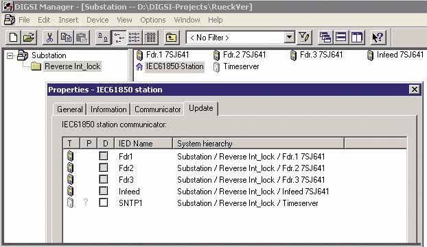
Switchgear Interlocking

                                                                                               The GOOSE information items each have
                                                                                               “CFC” as their source and the “system inter-
                                                                                               face” as their destination. Placing a cross in
                                                                                               the “System interface” destination column
                                                                                               causes DIGSI to ask for the logical node name
                                                                                               in the IEC 61850 designation. A meaningful
                                                                                               abbreviation can be entered at this point,
                                                                                               e.g. “SI” for switchgear interlocking (Fig. 3).
                                                                                               If the simple CFC charts for forming the infor-
                                                                                               mation items “Coupler closed” and/or “Busbar
                                                                                               disconnectors in Bay C01/C03 closed” have

                                                                               LSP2850en.eps
                                                                                               been created, the CFC charts can also be added
                                                                                               for the switchgear interlocking (second step).
                                                                                               This is done by including the additional infor-
Fig. 2 GOOSE information items in the DIGSI matrix (example of coupler C02).                   mation in the release of the busbar
                                                                                               disconnectors (bays C01 and C03) and/or the
                                                                                               coupler circuit-breaker (bay C02).
                                                                                               The third step is to close the DIGSI device en-
                                                                                               gineering and create an IEC 61850 substa-
                                                                                               tion. This is done in the DIGSI manager in the
                                                                                               same way as creating a device. A new “house”
                                                                                               icon appears with the text “IEC 61850 substa-
                                                                                               tion” (Fig. 4).
                                                                                               This icon can be used to start the system
                                                                                               configurator, which manages the IP addresses
                                                                                               of the subscribers and permits configuration
                                                                                               of GOOSE communication. First, the subscrib-
                                                                                               ers of the GOOSE communication are defined.
                                                                                               For this purpose, the substation is opened
                                                                                               with the right mouse button (via “Object
                                                                                               properties”) and the “Subscribers” tab is se-
                                                                                               lected (see Fig. 5 on the following page).
                                                                                               The upper area shows all available devices
                                                                               LSP2851en.eps

                                                                                               that can be moved into the lower area with
                                                                                               the arrow button. In this way, multiple
                                                                                               GOOSE units can be defined in one DIGSI pro-
Fig. 3 Query dialog box for newly created IEC 61850 information items
                                                                                               ject to keep configuration of the connections
                                                                                               simple. This is achieved by creating a new
                                                                                               IEC 61850 substation several times.
                                                                                               The IEC 61850 substation can then be opened
                                                                                               with a double click on the house icon. This
                                                                                               takes you to the system configurator with the
                                                                                               two views “Network” and “Connection”. Under
                                                                               LSP2852en.eps

                                                                                               “Network”, the IP addresses are assigned and
                                                                                               under “Connection” (Fig. 6), the GOOSE infor-
                                                                                               mation items are connected, as in the DIGSI 4
Fig. 4 “IEC 61850 substation” icon in the DIGSI 4 manager
                                                                                               matrix.

4                                                                                              Siemens E D EA · Application Examples for IEC 61850
Switchgear Interlocking

Bottom left and right, the GOOSE subscribers
are listed in the two windows “Sources” and
“Destinations”. In the “Name” column, the
IEC 61850 structure of the objects is visible
and in the “Description” column, you can see
the SIPROTEC texts. Under the logical device
“Control”, you will find in device C02 the logi-
cal node “SFSGGIO1” with the element “C02
coupler closed”. You insert this in the upper
“Connections” table using the “Add source”
button. In the bottom right window “Destina-
tions”, you then choose the two correspond-
ing information items that have the same
name in devices C01 and C03 and move
these to the “Destination” column. The con-
nection of these information items is now sto-
red in the system.
In the same way, the information items
“Busbar disconnector closed” from the feeder
units are routed to the coupler. After this, the
system configurator can be re-closed.

                                                                                                                                     LSP2853en.eps
As soon as the device parameter sets have
been updated (triggered on the “Update” tab
of the window in Fig. 5), the device parame-
ter sets can be loaded. This update causes the        Fig. 5 Selection of the subscribers of a IEC 61850 substation
GOOSE information to be written into the
parameter sets.
After that, the parameters sets can be loaded
into the SIPROTEC devices in the usual way.
Again using a right mouse click on the substa-
tion, “Export IEC 61850 substation” can now
be selected. The SCD file is then stored with
all information for IEC 61850 communication.
This can then be imported by a client, for ex-
ample SICAM PAS. In our example, only the
information report is routed to the client via
the interface; the information required for the
interlocking across bays is handled solely
directly between the devices using GOOSE.                                                                                            LSP2854en.eps

                                                      Fig. 6 “Connection” view in the system configurator

Siemens E D EA · Application Examples for IEC 61850                                                                              5
Switchgear Interlocking

                     n 4. Monitoring concept                             In this fault case, it must be ensured that
                     Because GOOSE communication transmits               these interlocking conditions that process the
                     safety-relevant data for switchgear interlock-      non-available information remain blocked.
                     ing (and also for the reverse interlocking of       This is done by including the status in these
                     protection devices), monitoring of the con-         conditions. The status can be obtained from
                     nection is necessary.                               the information items with the status CFC
                     This monitoring must                                blocks in DIGSI 4 and then evaluated in the in-
                                                                         terlocking conditions.
                     a) Reliably detect and report a failure of the
                        communication line                               n 5. Summary
                     b) Work selectively, i.e. only report infor-        The use of IEC 61850-GOOSE enables imple-
                        mation items as faulty that can really no        mentation of “substation wide switchgear in-
                        longer be transmitted.                           terlocking” as a distributed application. This
                                                                         has the advantage of independence from a
                     For this purpose, monitoring is performed at
                                                                         centralized station controller and increased
                     two points in the system: first, at each
                                                                         availability. This example shows how wiring
                     Ethernet channel, monitoring has the task of
                                                                         between bay control units is replaced easily
                     checking whether a connection to a switch
                                                                         and reliably by GOOSE-telegrams. In various
                     exists. This also enables detection of failure of
                                                                         projects around the world, Siemens has suc-
                     one channel in redundant communication,
                                                                         cessfully implemented this concept. Stan-
                     while communication is running via the sec-
                                                                         dardization of the IEC 61850 interface also
                     ond channel. For example, it is possible to
                                                                         makes it possible to build up interoperable so-
                     take remedial action in time and maintain
                                                                         lutions. In the GOOSE network, information
                     availability.
                                                                         can be exchanged between equipment of dif-
                     Second, the status of an information item can       ferent manufacturers. This means that custo-
                     be evaluated. If the required communication         mers can now build their substation with
                     channel is interrupted, the bit “NV” for “not       devices from different manufacturers, which
                     valid” is set. This example illustrates this with   was previously only possible for the protec-
                     the assumption that the connection between          tion equipment.
                     C01 and C02 has been interrupted (Fig. 7).

                         Interrupted connection

          Fig. 7 Interrupted connection between 2 devices

                     In this case, the following information is
                     invalid:
                     • “Coupler closed” in device C01
                     • “Busbar disconnector in bay C01 closed” in
                       coupler C02

                     Additionally, the interrupted connections are
                     shown in devices C01 and C02 ("Channel 1
                     faulty”).
                     The devices C02 and C03, on the other hand,
                     can continue to communicate undisturbed.

6                                                                        Siemens E D EA · Application Examples for IEC 61850
Reverse Interlocking

Reverse Interlocking Using
the GOOSE of IEC 61850

n 1. The principle of reverse interlocking
Reverse interlocking provides a low-cost way
                                                                                   Incoming feeder with
of implementing busbar protection in conjunc-                                      transformer
tion with time-overcurrent protection devices
                                                                                           Infeed
7SJ62 (Version 4.7 and higher) and 7SJ64.
These devices have the performance required
                                                                                             BI         Blocking of the I>> stage
to execute time-critical protection applications                                                        (active without voltage)
using GOOSE. The busbar is powered through
a transformer feeder and the other feeders
(Fdr.1 – Fdr.3) go to the loads (see Fig. 8).
If very short tripping times of under 15 ms are
required, a 7SS60 or 7SS52 busbar protection
system must be used.                                                Overcurrent                     Overcurrent                     Overcurrent
                                                                    I> picked up                    I> picked up                    I> picked up
In IEC 61850, a time-overcurrent protection
stage (DMT/IDMT) is described by the logical
node “Protection Time Overcurrent” (PTOC).
Pick-up of the stage is termed “Start” (str);                         Fdr. 1                           Fdr. 2                          Fdr. 3
tripping is termed “Operate” (Op). There is a                                                                                          Loop line
parameterizable low-set or high-set current
stage (I> or I>>). If this is exceeded by the         Fig. 8 Simple busbar protection using reverse interlocking
short-circuit current, the stage is picked up
immediately (I> picked up / PTOC.str).
                                                      n 2. Intended response of the interlocking
After a parameterizable time delay T has
                                                            to a short circuit
elapsed, a trip command for the stage is
issued (I> Trip / PTOC.Op).                           2.1 External short circuit on a feeder
                                                      An external short circuit at position 1 (see Fig. 8)
On pick-up (I> picked up / PTOC.str) of the           results in pick-up of the I> stage of the unit
time-overcurrent protection stage I> in fee-          on feeder 1. This pick-up is routed to a nor-
ders 1 – 3 (Fdr.1 – Fdr.3), the I>> stage of the      mally-closed contact and blocks the I>> stage
incoming feeder is blocked via a binary input.        of the incoming feeder via the binary input
The binary input is routed such that this             (BI) because the binary input is de-energized
blocking is active without a voltage. The I>>         when the contact opens. The short circuit is
stage of the incoming feeder is set with the          cleared by the time-overcurrent protection
delay time T (70 – 100 ms) so that reliable           device of the short-circuited feeder when its
blocking is ensured by a pick-up (str) in the         delay time has elapsed.
feeders before the time delay of this stage
elapses in the incoming feeder. During nor-           2.2 Short circuit on the busbar
mal operation, a voltage is applied to the bi-
                                                      The I>> stage of the incoming feeder is set to
nary input via a loop line through the closed
                                                      reliably pick up value in response to a busbar
contacts. This means that the high-set I>>
                                                      short-circuit. A busbar short-circuit at posi-
stage is not blocked and trips after the delay
                                                      tion 2 does not result in pick-up by the
time on pick-up of the I>> stage.
                                                      I> stages of the devices in feeders 1 to 3.
                                                      After the set delay time T has elapsed, a trip
                                                      command is issued and the short circuit is
                                                      cleared.

Siemens E D EA · Application Examples for IEC 61850                                                                                                7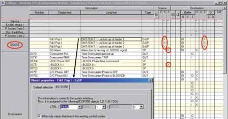
Reverse Interlocking

    Voltage at the BI
    of the infeed
                                                            1

         Overcurrent: I> picked up = 0                                                                                    I> picked up = 0
         (contact close)                                                                                                  (contact close)
                                                            I> picked up = 1
                                                            (contact opens)                                                                                t

    Cyclic GOOSE               Cyclic GOOSE       Spontaneous GOOSE                                                  Spontaneous GOOSE       Cyclic GOOSE
    I> picked up = 0           I> picked up = 0   I> picked up = 1                                                   I> picked up = 0        I> picked up = 0
                                  Transmitted
                                   telegram

                                                        1       2 ms     4 ms         8 ms                                    1   2 ms                     t

                                                                                                                                                                LSA4765.eps
        Cyclic repeat time e.g. 0,5 s 12 μs                        First repetition

Fig. 9 How binary states are transmitted with GOOSE telegrams

                                                                                                        ge, a GOOSE telegram is transmitted sponta-
                                                                                                        neously. This telegram is repeated after 1 ms,
                                                                                                        2 ms, 4 ms etc. before returning to cyclic ope-
                                                                                                        ration. The repeat time after a spontaneous
                                                                                                        change is also configured in the system confi-
                                                                                                        gurator. If the pick-up drops off again within
                                                                                                        this time, the spontaneous transmission is re-
                                                                                                        peated. Fig. 9 shows the method as applied
                                                                                        LSP2855en.eps

                                                                                                        to the pick-up signal. Each unit in the feeder
                                                                                                        transmits its GOOSE telegram to the unit in
                                                                                                        the incoming feeder.
Fig. 10 Station configuration in DIGSI
                                                                                                        n 4. Parameterization with DIGSI and
                                 n 3. Principle of GOOSE telegram                                             system configurator
                                       transmission (GOOSE messages)                                    4.1 Station configuration in DIGSI
                                       of IEC 61850                                                     First, a station is configured with the devices
                                 If a signal, e.g. the pick-up ”Overcurrent I>                          in DIGSI (see Fig. 10). In addition to the devi-
                                 picked up”, is configured in a GOOSE message,                          ces of the feeders and the incoming feeder,
                                 the unit sends this message cyclically every                           an IEC 61850 station is also required, which
                                 0.5 seconds as a telegram over the Ethernet                            will later contain the system configuration.
                                 network via Ethernet module EN100 at                                   Using the time server, which may be integrat-
                                 100 MBit/s. Such a telegram is just a few                              ed into the PAS master unit, the time in the
                                 microseconds long. The GOOSE message is                                devices is synchronized via the SNTP – proto-
                                 transmitted with high priority in the network.                         col via Ethernet. The devices only require the
                                 The cyclic repeat time can be set in the sys-                          network address (IP address) of the time
                                 tem configurator and should be set with “high                          server.
                                 priority” in protection applications. The con-
                                 tent of this telegram communicates the state
                                 of pick-up (not picked up or picked up) to the
                                 subscribers of the GOOSE message. The cyclic
                                 transmission enables each of the subscribers
                                 to detect a failure using a logic block when a
                                 transmitter has failed or a communications
                                 channel has been interrupted. This provides
                                 constant monitoring of the transmission line
                                 because the subscriber expects to receive a
                                 telegram at several-second intervals. This is
                                 equivalent to pilot-wire monitoring in conven-
                                 tional wiring. On a pick-up, i.e. a signal chan-

8                                                                                                       Siemens E D EA · Application Examples for IEC 61850
Reverse Interlocking
4.2 Settings in the devices of the feeders
Only settings that are necessary for this appli-
cation are discussed here. In practice, there
will be further functions and routings to set.
The IED name must be entered under the
“Object properties” -> “Communication param-
eters”. It is required in the IEC 61850 configu-
ration to identify the device (see Fig. 11).
The network parameters are later set in the
system configurator.
The device must then be opened and saved
again to generate an IEC 61850 configuration
file (ICD file).
Under “Time Synchronization”, “Ethernet NTP”
LSP2856en.eps
is selected (Fig. 12). Settings for the time
zone and daylight-saving/standard time swit-
chover can be set for a specific region. With
this setting, the device queries the SNTP timer Fig. 11 Setting of the communication parameters
about once a minute. The IP address of the
time server is set in a standardized way for all
devices in the system configurator and does
not have to be configured separately in each
device.
In the network topology (see Section 5), the
devices works with an integrated switch in
the optical ring. Under “Communication” ->
“Ethernet on device”, “Switch” mode must be
chosen for the optical module (Fig. 13). This
setting must be made in the optical ring for
each device. This dialog box also allows you
to check the set IP address later.
In the routing matrix, the signals to be trans-
LSP2857en.eps
mitted as the destination via the system inter-
face S are configured. Because the I> picked
up indication is defined as a mandatory mes-
sage in the IEC 61850 standard, it is already Fig. 12 Time setting dialog box in DIGSI
routed to S and cannot be unrouted by the
user. With a right-mouse click on the message,
it is possible to view the IEC 61850 message
text under “IEC 61850” (PROT/PTOC6/Str).
This information is also seen as plain text in
the protocol and will later be required in the
system configurator (see Fig. 14 on the fol-
lowing page). After that, the unit is saved and
DIGSI automatically creates all the data of the
device that is necessary for IEC 61850 config-
uration.
LSP2858en.eps
Fig. 13 Settings for the integrated switch
Siemens E D EA · Application Examples for IEC 61850 9Reverse Interlocking
long text are edited for the message (DIGSI
text). The message is routed to the system
interface as a source and must be provided
with an IEC 61850 message text in a property
window (see Fig. 15). The structure of the
text is largely defined by the standard. This
text is required in the system configurator.
The messages are routed into the logic editor
“CFC” as destination and further processed
there. Blocking of the I>> stage “>Block I>>”
LSP2859en.eps
is routed to the CFC as the source because the
blocking is mapped there by logic blocks. Mo-
reover, a further message is created in the
Fig. 14 Routing of the pick-up message on system interface GOOSE group that generates an alarm if
IEC 61850 message text in “Object properties” window there is a disturbance in the GOOSE link
(GO-alarm). This information can, for exam-
ple, be routed to an LED, a contact, or the sys-
tem interface as the destination and used as
an alarm in the substation control unit.
4.4 Settings in the CFC in the device of
the incoming feeder
With a little logic, the blocking and alarming is
performed in the CFC. Time-critical protection
applications must be processed in the fast
LSP2860en.eps
CFC charts. The new chart is named GOOSE.
Blocks of category “SI_Get_Status (Decoder)”
are inserted and each is connected to the
Configured IEC 61850 message text pick-up signals of the right-hand margin
Fig. 15 Settings in the device of the incoming feeder in the routing matrix (sources) (see Fig. 16). Such a block has a
“Value” output that indicates the ON/OFF
Left margin with Right margin state of the message at the input. The “NV”
pick-up signals with DMT/IDMT output stands for “not valid”. If a GOOSE sig-
received via I>> blk and GOOSE nal is no longer received, this output is set.
GOOSE Status- alarm
blocks OR gate The pick-up signals are connected to an
“OR block” whose output goes to the blocking
of the I>> stage on the right-hand margin.
The NV outputs are connected with the GOOSE
alarm via an OR block. Depending on the
operator philosophy, this signal can also be
LSP2861en.eps
used for other actions, e.g. blocking the stage.
Fig. 16 Formation of the blocking I>> stage and the GOOSE alarm in the CFC
4.3 Settings in the device in the incoming
feeder
Here, more extensive settings must be made.
“Ethernet NTP” is selected as the time syn-
chronization source and the integrated switch
is set.
A new information group is inserted in the
routing matrix and named “GOOSE”. Here,
new messages of the object type “External
single point” from the information catalog are
required. For each transmitted pick-up indica-
tion of a feeder, a corresponding message is
required with which the start message is fur-
ther processed. A meaningful short text and
10 Siemens E D EA · Application Examples for IEC 61850Reverse Interlocking
4.5 Settings in the system configurator
(Fig. 17)
First of all, all IEC 61850 devices of the station
are added to the system configurator. This
also adds the ICD files of the devices. This is
Source Destination
done in the “Station Manager” with a signals signals
right-mouse click on the IEC 61850 station
under “Object properties” -> “Communicator”.
Then the system configurator is opened.
There, the first step is to set the IP addresses
of the devices. DIGSI suggests network
LSP2862en.eps
addresses, which are normally accepted. Note
that network addresses of other devices, for
example, the time server, the PAS, and the
switches must be set with the configuration Fig. 17 Configuration of the signal connections in the system configurator
software of these devices. Only the IP ad-
dresses of SIPROTEC units are configured with
DIGSI. Moreover, the system configurator
does not show all devices. To avoid network
conflicts due to duplicate IP addresses, it is
advisable to draw up a list of all network de-
vices.
The next step is switchover to the connection
view. The system configurator offers a de-
fault GOOSE application that is renamed in
the right-hand “Properties” window (Reverse
LSP2863en.eps
Interlocking) and is set to high priority. This
means that the GOOSE messages are repeat-
ed cyclically and spontaneously with high
frequency: every 0.5 s cyclically, starting with
Fig. 18 Updating of the devices with the IEC 61850 configuration
1 ms repetition on a spontaneous change to a
message.
4.6 Loading of the configuration data
The devices are listed with their signals on the into the devices
left-hand side below. For each device, the Under “Properties” (right mouse click on
protection pick-up must now be inserted as IEC 61850 station) and “Update” the parame-
the source signal in the connection view. It is ter sets of the devices are now updated with
helpful if the familiar SIPROTEC texts are dis- the IEC 61850 relevant data. The devices only
played along with the IEC 61850 standard have to be initialized once via the front serial
text (e.g. Fdr1.PROT.PTOC6.str.general). On interface. Then they are assigned with net-
the right, the destination signals are available work addresses and IEC 61850 configuration
that have been configured as “External single data. Further updates can be performed via
point indications” in the device of the incom- the Ethernet interface (Fig. 18).
ing feeder. In the connection view, a “Source”
is now connected to the “Target”. This is equi-
valent to conventional wiring of a contact to a
binary input. A source signal can also be con-
nected to multiple destinations, although this
is not required in this case.
When configuration has been completed, it is
saved and the system configurator is closed.
A configuration file of the station (SCD file)
is then generated automatically, which is in
conformance with the IEC 61850 standard
part 6.
Siemens E D EA · Application Examples for IEC 61850 11Reverse Interlocking
PAS master unit with time
n 6. Summary
synchronization (SNTP) and Using the peer-to-peer communication of
network monitoring (SNMP)
IEC 61850, parallel wiring between bay con-
Fiber-optic cable
trol units can be replaced by GOOSE. This can
Electrical
also be used for time-critical protection appli-
Ethernet Ethernet cable cations. This requires the use of devices with
Operating Multi-mode fiber switch
PC with high computing power, such as 7SJ64, 7SJ62
DIGSI as from Version 4.7, 7SA52/6, 7SD52/6,
62.5/125 μm or 50/125 μm
7UM62, and 6MD66. In place of hardwiring,
the DIGSI software is now used for configura-
tion according to the methods standardized in
IEC 61850.
Optical links permit reliable operation. Due to
the ring topology of the network and exten-
Fdr. 1 Fdr. 2 Fdr. 3 Incoming Fdr.
sive monitoring functions, component failure
can be detected in a matter of seconds. This
Fig. 19 Structure of the Ethernet network as an optical ring results in high availability because operation
can continue even if one component fails.
n 5. Network topology These monitoring mechanisms are compara-
The network is implemented as an optical ble with the constant pilot supervision of wire
ring that is terminated with a switch connections, which is usually only implement-
(see Fig. 19). At this point, a PAS master unit ed for tripping circuits because of the extra
is connected. This unit is not involved in the costs incurred for external components.
GOOSE application but may, for example, Using the GOOSE mechanism of continual re-
read out messages and fault recordings from petition of telegrams and intelligent monitor-
the devices and can pass on the GOOSE ing modules in the device, monitoring is im-
alarm. It can additionally monitor the topol- plemented in the software, as is already the
ogy of the network, which is implemented state of the art in digital communication links,
using a special monitoring protocol SNMP. for example in differential protection.
It also performs time synchronization in the
Nevertheless, the method does require thor-
network with 1 ms accuracy via the Simple
ough commissioning that verifies correct
Network Management Protocol (SNTP).
functioning and checks the time response.
In the devices, an optical Ethernet module This is supported by the internal logging of
with an integrated switch is used. This achie- the devices and test tools. Test equipment
ves a maximum of electromagnetic immunity and software tools are now available that
and fault-free data transmission. With con- trace the GOOSE messages on the bus and
ventional wiring, the signal wires can be pro- make a record with millisecond precision, in
ne to high interference voltages. Except for the same way as for binary signals that are
the SIPROTEC devices, few other network generated via contacts.
components are required, which reduces the
configuration effort and increases the reliabi-
lity of the system. The failure of one device is
tolerated in the optical ring because the net-
work restructures itself into two chains in a
matter of milliseconds and the devices can
continue to intercommunicate. The data traf-
fic is controlled by special filters on the optical
module to ensure that GOOSE telegrams are
only listened to in the devices that expect in-
formation from a GOOSE telegram. This redu-
ces the processor load on the Ethernet
module, which is not constantly troubled with
telegrams with irrelevant content, as GOOSE
telegrams are always sent to all devices.
GOOSE telegrams are also prioritized over re-
gular data traffic, which is a special feature of
the IEC 61850 GOOSE. A GOOSE message
passes through the integrated switch of a
device in 4 s, so that it runs through the ring
almost without delay.
12 Siemens E D EA · Application Examples for IEC 61850Beneficial Engineering
Beneficial Engineering of
IEC 61850 Substation Automation
Systems
n 1. Introduction n 2. Engineering process
Engineering expenses dominate both the in- Engineering an SAS to the point of system
vestment costs of an SAS (Substation Auto- completion and operation involves several
mation System). Consequently, the main way project phases. Aside from commercial and
to reduce these costs is to optimize the engi- project management matters, all of the
neering process. project‘s technical concerns fall in the catego-
ry of engineering. In the substation-automati-
The process of engineering an SAS involves
on domain, the term engineering includes all
several activities: system design and specifica-
technical activities necessary for building and
tion, device and system configuration,
running an SAS over its complete life cycle –
device parameterization, documentation,
including modifications and extensions.
testing and diagnostics, and commissioning.
These engineering activities include: system
Each activity includes several system levels,
specification, device and system configura-
ranging from process interface, protection,
tion, device parameterization, documenta-
and communication settings up to SCADA
tion, testing, diagnostics, and commissioning.
functionalities.
The current practice in engineering an SAS is 2.1 Engineering roles and active parties
to use vendor-specific tools, each of which is During the engineering of a substation auto-
designed for a particular engineering activity mation project, several parties are involved.
and a particular system level. As a conse- Typically, the active parties include the utility,
quence, the engineer ends up using a chain the consultant, the service provider, and the
of tools, especially in multi-vendor applica- vendor. Depending on the project conditions,
tions, and expending a lot of effort on data these parties can play different roles regard-
entry (often entering the same data multiple ing engineering activities. With respect to the
times into various tools), data exchange, and engineering phase of a project (commercial
manual data conversion between tools. In ad- matters are already clarified), the basic roles
dition, these tools rarely support the reuse of include system owner, system integrator, and
engineering data from existing installations in operator. The role of the system integrator in-
new or retrofitted projects. cludes all activities from system design and
The communication standard IEC 61850 planning through the commissioning stage.
offers great hope for simplifying this process. Thus it is not unusual for the role of system
With its object-oriented data model and for- integrator in a project to be split among
mal description language, it promotes reusa- multiple parties.
bility, data interoperability, and seamless In most projects, the utility specifies the SAS
engineering. and buys a turnkey system. In this case, the
In the pages that follow, the challenges in- utility is usually the system owner and opera-
volved in the process of engineering an SAS tor, while the vendor or service provider is the
are described. Then, the requirements for an system integrator.
efficient and comprehensive work flow both In addition, various other arrangements are
in the project process and at the system level possible, with the active parties playing differ-
are defined. Then, it is shown how ent roles, see bibliography on page 19,
IEC 61850’s intelligent methodologies can reference [1].
overcome these limitations and improve engi-
neering efficiency.
Siemens E D EA · Application Examples for IEC 61850 13Beneficial Engineering
Engineering Activities
Design & Device & System Device Testing & Commissioning
Documentation
Specification Configuration Parameterization Diagnostic & Operating
Control
System Levels Center
HMI Station Unit
Application (HMI)
Station
Level
Communication (CC-Interface)
Communication (Station Bus) IEDs
Bay
Level
Application (Protection & Control)
Process Interface Process
Process
Level
Fig. 20 Engineering activities and system levels
2.2 Engineering activities trol hierarchy, interlocking, and the HMI de-
Fig. 20 shows the engineering activities and sign (including how all these functions are
system levels involved in erecting or retrofit- distributed to IEDs). The design process in-
ting a typical SAS. The structure of the SAS volves defining details such as process param-
consists of bay controllers and protection eters (for example, current and voltage
relays, which are connected to the primary scaling), system parameters (for example,
equipment via a process interface. These data exchanged for interlocking purposes),
IEDs at the bay level communicate with each and setting values (for example, pick-up val-
other, and with IEDs at the station level, via a ues for the overcurrent protection). The result
communication infrastructure. Communica- is an application-specific data model that is
tion to a remote control center is imple- represented by specifications typically docu-
mented by a WAN connection. mented in the form of written requirement
specifications, including flow-charts and sig-
Due to these different system levels – ranging nal lists.
from process interface up to SCADA functio-
nalities – engineering is carried out both in Based on these specifications, a system con-
the horizontal direction (activities) and in the figuration and appropriate IEDs meeting the
vertical direction (system levels) in order to functional requirements are selected.
complete a system.
b) Device and system configuration
A short description of the engineering activi-
This phase involves configuring the selected
ties is given below.
SAS solution. A system integrator usually per-
forms this task.
a) Design and specification
This phase involves planning and specifying Configuration typically begins with devices.
the layout, functions, and applications of an Starting from the requirement specifications,
SAS. These tasks can be carried out by the the desired functions and applications are
utility, the service provider, the consultant or translated into a device-specific data model
the vendor. and operation code. These include protection
settings, interlocking terms, CFC-Logic, HMI
Generally, the requirements of the primary mimics and diagrams. Device-specific tools
system determine the design of the second- are used for configuring these items.
ary system. The functions and applications of
the primary system regarding protection, The communication infrastructure can be
operation, and monitoring are compiled and seen as the backbone of an SAS. Merging the
mapped to the secondary system according to devices to a system by communication is the
each application. Usually, the customer’s phi- scope of system configuration. In system con-
losophy and requirements influence the spec- figuration, the communication parameters
ifications of the functions and applications in are set in order to determine what data is
areas such as the protection scheme, the con-
14 Siemens E D EA · Application Examples for IEC 61850Beneficial Engineering
exchanged – and how it is exchanged – be- multiple system levels and activities. But in
tween devices, station unit, HMI, and remote multi-vendor applications – typically in high
control centers. voltage (> 110 kV), exchange, or extension
projects – tool import and export qualities
c) Device parameterization play a major role.
In this phase, the system integrator deploys The use of multiple tools in a project has the
the device-specific data models, settings, and following consequences:
operation code to the appropriate devices.
Naturally, device-specific tools are used for • The engineer has to pass the process
downloading the data to devices. through a chain of tools, often with itera-
tion loops.
d) Testing and diagnostics • The same data must be entered multiple
Testing and diagnostics are crucial for con- times for different devices and system
firming proper operation of an SAS – or for levels.
trouble-shooting, in case of malfunction. • System integrators and operators have to
The testing and diagnostic tools are predomi- handle a multitude of devices and tools (va-
nantly vendor-specific, often functionally rying in type, manufacturer, technology,
integrated within device configuration tools. and modeling), each of which requires
Extensive testing takes place during FAT, appropriate training and know-how.
commissioning, and SAT, usually with the
support of monitoring and diagnostic tools. The data models of most tools are strongly
signal-oriented. As a result, mapping data to
e) Documentation HMI applications requires extensive conver-
The documentation is carried out by a system sions to technology-oriented objects (e.g. cir-
integrator and includes: cuit breakers, disconnectors, transformers,
and so on).
• Electric circuit diagrams of the complete
SAS In addition, it is common in project activities
• Signal lists that most artifacts (requirement specifica-
• Communication address lists tions, documents, signal lists, data models,
• Parameter settings (process, protection, and so on) are neither standardized nor uni-
and communication) form. These items are strongly influenced by
• Data lists for bit tests customers’ and vendors’ work practices, tools,
• Operational and technical manuals and philosophies. So, the following limita-
• Acceptance reports tions and consequences occur:
• Commissioning reports • Extensive data conversions are required
among tools
f) Commissioning and operation • Reuse of engineering data is difficult
Commissioning begins after the system is in-
stalled and passes its acceptance tests. The
system integrator usually performs this task,
together with the owner or the operator or
both. During the operation phase, periodic or
condition-based maintenance activities take
place. In addition, modifications or even
system extensions may require
re-engineering.
2.3 Limitations and issues
In practice, the engineering process described
above is rarely seamless and straightforward
– mainly because it requires vendor-specific
tools designed for a particular engineering ac-
tivity and system level, and the use of propri-
etary data models. Projects with a homo-
genous system platform (all devices from the
same vendor) involve relatively minor issues,
as the tools are usually coordinated to cover
Siemens E D EA · Application Examples for IEC 61850 15Beneficial Engineering
n 3. Requirements • Decoupling of data model and communica-
To avoid the above-mentioned limitations and tion services from specific communication
issues, an efficient engineering process needs technologies. This technology independ-
to meet the following requirements regarding ence guarantees long-term stability for the
data models and tools: data model and opens up the possibility
of switching over to successor communi-
• Standardized and technology-oriented data cation technologies, see bibliography on
model page 19, ref. [7].
• Unified interchange format for data-model • A common formal description code, which
representation allows a standardized representation of a
• Standard import and export interfaces for system’s data model and its bindings to
all tools communication services, see bibliography
• Template support for easy reuse of engi- on page 19, ref. [8]. This code, called SCL
neering data in all types of cases, from (Substation Configuration Description
simple system extensions up to delta engi- Language), covers all communication
neering of complete systems aspects according to IEC 61850. Based on
• An interface that hides complexity from XML, this code is an ideal electronic inter-
users as a default, with expert mode avail- change format for configuration data.
able on demand It provides for the following four types of
• A single-tool model (covering a wide prod- SCL files:
uct range) in order to reduce the number of
tools used in a project – SSD (Substation Specification Descrip-
• Integrated communication configuration tion) files: these include primary equip-
capabilities to further reduce the number of ment and topology information and its
tools used per project bindings to basic application functions.
• Vendor-independent testing and diagnostic The use of SSD files is optional.
tools – ICD (IED Capability Description) files:
• Well defined interfaces between user roles these include information about the
functional capabilities of an IED.
n 4. Benefits of IEC 61850 engineering
4.1 Key features of the IEC 61850 standard – SCD (Substation Configuration Descrip-
The short abstract that follows provides a ba- tion): these include the configured data
sic understanding of IEC 61850 – its princi- models and communication settings of
ples, concepts, and methodologies. all IEDs participating in an SAS
Unlike other applied communication stand- – CID (Configured IED Description)
ards, such as IEC 60870-5-101 /-103 /-104, is an IED-specific subset of the SCD,
the IEC 61850 standard goes beyond just which includes all relevant information
communications. for an IED. Its use is optional.
Key features are: • A description of requirements of the system
• An object-oriented and application-specific and project management process and of
data model focused on substation automa- special tools for engineering, see bibliogra-
tion, see bibliography on page 19, ref. phy on page 19, ref. [9]
[2-4]. This model includes object types re-
presenting nearly all existing equipment With SCL, the IEC 61850 standard introduces
and functions in a substation – circuit- a powerful and unique feature into the sub-
breakers, protection functions, current and station-automation domain. SCL allows a uni-
voltage transformers, waveform recordings, form and vendor-neutral representation of a
and many more. system’s communication configuration to be
• Communication services providing multiple used over the complete system life-cycle.
methods for information exchange. These
services cover reporting and logging of
events, control of switches and functions,
polling of data-model information, real-
time peer-to-peer communication (GOOSE),
sampled value exchange, and file transfer
for disturbance recordings, see bibliogra-
phy on page 19, ref. [5, 6].
16 Siemens E D EA · Application Examples for IEC 61850Beneficial Engineering
Engineering Activities
Design & Device & System- Device Testing & Commissioning
Documentation
Specification Configuration Parameterization Diagnostic & Operating
Functional &
operational
requirements Tools Archive
Changes,
extensions
Fig. 21 The principles of SCL-centered engineering. ICDs = IED Capability Description files,
SCDs = Substation Configuration Description files.
4.2 The SCL-centered engineering process
Today vendors offer powerful tools which are such tools offer the benefit of automatical-
capable of handling SCL and meeting the ly creating the 61850 data model. For
requirements in terms of beneficial enginee- example, in the case of a tool for control
ring. These tools make the SCL-centered engi- and protection devices, when the control of
neering process a reality. The sections that a switch is required, the tool automatically
follow describe the SCL-centered engineering maps it to the IEC 61850 domain by crea-
methodology and present its benefits. Fig. 21 ting appropriate instances of data objects
illustrates how the SCL files are passed (logical nodes XSWI, CSWI, CILO).
through engineering activities.
b) Device and system configuration
a) Design and specification The detailed configuration of application func-
Specification data that is not relevant for tions – such as protection, control, interlock-
communication is still in the form of draw- ing, and so on – is within the scope of device
ings, tables, and CFC charts. The system spe- configuration. With its uniform naming con-
cification can be carried out with a dedicated vention, the IEC 61850 data model allows the
system specification tool in order to create an use of seamless object and signal names in
SSD file, but this method first may provide tools. Object-oriented filtering offers distinct
real benefits for substation to control center advantages in configuration, especially during
communication in the future. configuration of the HMI and the control
center.
However, all specification data directly appli-
cable to communication can be covered by The system configuration includes all use
means of IEC 61850. Therefore it is important cases for the configuration of communication
to select suitable devices that provide speci- applications. This configuration can be per-
fied functionality and map the application- formed by the system configurator tool, which
specific data to the IEC 61850 data model. is advantageously implemented in the device
The result of such device specification is the configuration tool. The system configurator
collection of ICD files in accordance with the tool imports all ICD files and sets basic commu-
IEDs that are used. nication settings (e.g. IP addresses), report
configurations, and GOOSE configurations.
Benefits: In this manner, it creates the system’s SCD
• Selection of conformance-certified IEDs. file.
With its standardized conformance testing,
the standard allows selection of devices Benefits:
with conformance certificates. This ensures • Seamless naming of data objects. Standard
a high degree of interoperability and naming conventions simplify data mapping
performance. to HMI and control-center applications.
• Automatic creation of IED-specific • Simple handling of communication. Hiding
IEC 61850 data models in the form of ICD complexity from users simplifies configura-
files. In the case of device specification,
Siemens E D EA · Application Examples for IEC 61850 17Beneficial Engineering
tion and makes it easier to focus on the ap- f) Commissioning and operation
plication itself. The standardized and technology-oriented
• Built-in quality management. The built-in data model of the IEC 61850 standard, when
support of revision tags in SCL allows more combined with a tool that supports object-
effective detection of changes in configura- oriented templates, opens various benefits for
tion files. In addition, the provided tools current and future systems. In addition, the
validate the IED model against the standard comprehensive IED data models provide valu-
and check its consistency. able information for the utility.
c) Device parameterization Benefits:
The SCD file is deployed to all participating • Simple changes and extensions. When an
IEDs. After importing the SCD file, the device IED is modified, any changes in a template
tools extract the relevant data subset and are propagated to all instances of this tem-
download the configuration data to the IED. plate. Templates can also allow creation of
a new bay, including all necessary IEDs –
Benefit: a much more efficient method than using
• One common configuration file for all IEDs. copy and paste.
No additional device-specific communica- • Access to maintenance data. During opera-
tion configuration is needed. tion, it is easy to read information needed
for asset management, including name
d) Testing and diagnostics plates, switching operation counters,
Based on Ethernet technology and on a stand- switching currents, and so on.
ardized protocol stack, the IEC 61850 stand-
ard offers several advantages for testing and 4.3 Delta engineering
diagnostics. Delta engineering is the most efficient way to
engineer a new system. It involves taking an
Benefits:
existing configuration and applying changes
• Simulation and testing of IEDs. With special and extensions in order to meet the new
testing tools, it is possible to test communi- requirement specification. This method is
cation behavior by simulating heavy net- not new, but with IEC 61850’s benefits –
work traffic or special telegrams. These especially its data model – a higher level of
tools – and also the testing equipment for reusability is attainable.
protection functions – can import SCD files
for simpler handling. n 5. Summary
• Vendor-neutral testing and diagnostic tools
Optimizing the engineering process offers
allow staff training to focus on fewer tools.
great potential for reducing investment and
Due to the standardized protocol stack of
installation costs of substation automation
IEC 61850-8-1, object browsers of IED ven-
systems. The IEC 61850 standard provides
dors or test equipment manufacturers can
several features that allow streamlining of all
be used for all IEC 61850-compliant IEDs –
activities from specification up to the opera-
and for network-traffic analysis tools that
tion phase.
are well established outside the substati-
on-automation domain. A promising lever for increasing efficiency of
engineering in substation automation is the
e) Documentation vertical expansion of the IEC 61850 standard.
The SCD file represents the electronic docu- By closing the gaps between substations and
mentation of the communication configura- control centers and between process and bay
tion of an SAS. This file offers the following level, the IEC 61850 standard’s seamless com-
advantages for documentation purposes: munication will overcome the last of the com-
munication discontinuities.
Benefits:
• One common representation of the com-
munication configuration of a complete
system.
• Automatic creation of data lists for commu-
nication tests.
18 Siemens E D EA · Application Examples for IEC 61850Beneficial Engineering
Bibliography
[1] K.-H. Schwarz “Impact of IEC 61850 on [5] IEC 61850-8-1, "Communication
system engineering, tools, peopleware, networks and systems in substations –
and the role of the system integrator”, Part 8-1: Communication Service
Proceedings of Distributech, San Diego, Mapping (SCSM) – Mappings to MMS
USA, Feb. 2007. (ISO 9506-1 and ISO 9506-2) and to
ISO/IEC 8802-3", Ed. 1, May 2004.
[2] IEC 61850-7-1, "Communication
networks and systems in substations – [6] IEC 61850-9-2, "Communication
Part 7-1: Basic communication structure networks and systems in substations –
for substation and feeder equipment – Part 9-2: Specific Communication Service
Principles and models", Ed. 1, Jul. 2003. Mapping (SCSM) – Sampled values over
ISO/IEC 8802-3", Ed. 1, Apr. 2004.
[3] IEC 61850-7-3, "Communication
networks and systems in substations – [7] IEC 61850-7-2, "Communication
Part 7-3: Basic communication structure networks and systems in substations –
for substation and feeder equipment – Part 7-2: Basic communication structure
Common data classes", Ed. 1, May 2003. for substation and feeder equipment –
Abstract communication service interface
[4] IEC 61850-7-4, "Communication
(ACSi)", Ed. 1, May 2003.
networks and systems in substations –
Part 7-4: Basic communication structure [8] IEC 61850-6, "Communication networks
for substation and feeder equipment – and systems in substations –
Compatible logical node classes and data Part 6: Configuration description
classes", Ed. 1, May 2003. language for communication in electrical
substations related to IEDs", Ed. 1,
March 2004.
[9] IEC 61850-4, "Communication networks
and systems in substations –
Part 4: System and project management",
Ed. 1, Jan. 2002.
Siemens E D EA · Application Examples for IEC 61850 19Beneficial Engineering 20 Siemens E D EA · Application Examples for IEC 61850
Innovative Solutions with IEC 61850

Innovative Solutions for
Substation Control with IEC 61850

n 1. Introduction                                     from different manufacturers, provide
Since IEC 61850 was published as an interna-          long-term investment protection and imple-
tional standard for communication in substa-          ment efficient exchange of object-oriented
tions, the standard has found broad accept-           data models between engineering systems.
ance on the markets. In the first substations         In addition, IEC 61850 offers the possibility of
to use it, the primary aim was successful             replacing parallel wiring with Ethernet and of
implementation of existing concepts and               implementing fast information exchange be-
solutions using the new technology. This              tween devices. This article chiefly deals with
positive experience from the initial projects         this aspect and contrasts these concepts with
secured the trust of the substation operators.        the conventional approach.
However, these substations did not yet make           Two practically proven examples demon-
use of the potential of IEC 61850.                    strate how modern solutions for digital substa-
With the rapidly growing number of imple-             tion automation incorporating new functions
mented substations, confidence grew in the            from IEC 61850 increase the benefit for users.
equipment and the first applications arose            The application examples are
that made specific use of the new technolo-           2. Distributed synchro-check (page 22)
gy. The most frequent control applica-                3. Mash station automatic switching (page 24)
tion was the decentralization of switchgear
interlocking using GOOSE messages.
The new communication standard contains
much more comprehensive definitions than
other protocols and is primarily intended to
improve interoperability between devices

Siemens E D EA · Application Examples for IEC 61850                                                                             21
You can also read