Engine Concept for Operating on Fuel Gas - Sisu Diesel 420 DWRIE Gerard Benseny Ràfales - Sisu Diesel 420 ...
←
→
Page content transcription
If your browser does not render page correctly, please read the page content below

Engine Concept for Operating on Fuel Gas -
 Sisu Diesel 420 DWRIE

Gerard Benseny Ràfales

Guillem Prats Teixido

Bachelor Thesis for Bachelor of Engineering

Degree Programme in Energy Technology

Vaasa, Finland, 2021
ACKNOWLEDGEMENTS

We would like to thank our esteemed supervisors Philip Hollins and Leif Backlund for their
continuous help and advice during this thesis. Their knowledge and constant feedback steered us
through this research. Our gratitude extends to Kaj Rintanen and the Novia University of Applied
Science for their support in providing us with the required tools to conduct this thesis. Finally, we
would also like to express gratitude to the companies AGCO Power Inc and Sandfirden Technics,
for their support in providing technical documentation.

DEGREE THESIS

Author: Gerard Benseny Ràfales & Guillem Prats Teixido
Degree Programme: Mechanical Engineering
Specialization: Energy Technology
Supervisors: Philip Hollins and Leif Backlund

Title: Engine Concept for Operating on Fuel Gas

Date Number of pages Appendices
14.05.2021 71 4

Abstract

Alternative fuels for internal combustion engines, such as fuel gases, are a transition solution that
could be beneficial in reducing current engine emissions before the electric vehicle becomes
widespread. This thesis aimed to define the engine concept for converting an existing diesel
engine (Sisudiesel 420 DWRIE) in the Novia University of Applied Science (Vaasa, Finland)
laboratory, to a dedicated fuel gas engine, which will be used for academic and research purposes.

The thesis reviewed a range of available fuel gases and explored the possibilities for converting
the diesel engine to operate on the selected fuel gas, defining a feasible engine concept. The
resulting engine was simulated with GT-Power software to check its operation and performance.

As a result, it was found that Compressed Natural Gas was the most appropriate fuel for being
implemented, according to engine conversion feasibility, fuel availability, and storage ease.
Regarding the gas engine concept, it was determined to adopt a spark-ignition engine with a
Venturi air-gas mixer and a reduced compression ratio compared to the original engine. The
simulation results showed a consistent engine although there was a decrease in performance
compared to the diesel engine. The findings of the thesis can provide a basis for future research
in terms of engine optimization and engine concept physical implementation.
Language: English

Keywords: Fuel Gas, CNG, Diesel Engine, GT-Power, Sisudiesel, Natural Gas
TABLE OF CONTENTS

1. Introduction .................................................................................................................................. 1
2. Aims and objectives...................................................................................................................... 3
3. Review of literature ...................................................................................................................... 4
 3.1. Sisudiesel 420 DWRIE engine ................................................................................................ 4
 3.1.1. AGCO Power Inc. ............................................................................................................. 4
 3.1.2. Sisudiesel 420 DWRIE specifications ............................................................................... 5
 3.1.3. Diesel .............................................................................................................................. 7
 3.2. Review of available fuel gases ............................................................................................... 8
 3.2.1. Main characteristics of fuel gases ................................................................................... 8
 3.2.1.1. Biogas ....................................................................................................................... 9
 3.2.1.2. Natural gas and biomethane .................................................................................... 9
 3.2.1.3. Liquefied Petroleum Gas ........................................................................................ 10
 3.2.2. Fuel availability ............................................................................................................. 11
 3.2.3. Fuel gas selection .......................................................................................................... 12
 3.2.4. Compressed Natural Gas .............................................................................................. 13
 3.3. Engine modifications to operate on natural gas ................................................................. 17
 3.3.1. Natural gas engine requirements ................................................................................. 17
 3.3.2. Possible diesel engine modifications to operate on natural gas .................................. 18
 3.3.2.1. Ignition system ....................................................................................................... 18
 3.3.2.2. Compression ratio reduction ................................................................................. 18
 3.3.2.3. Fuel supply and mixing system .............................................................................. 20
 3.4. SGI-4 industrial gas engine – a case study ........................................................................... 21
4. Natural gas engine concept ........................................................................................................ 23
 4.1. Proposed strategies and concepts....................................................................................... 23
 4.1.1. Concept 1. SI engine with DI and the existing cylinder head ....................................... 24
 4.1.2. Concept 2. SI engine with DI and replaced cylinder head ............................................ 26
 4.1.3. Concept 3. SI engine with mixing device ...................................................................... 27
 4.2. Selected engine concept...................................................................................................... 29
4.2.1. Ignition system .............................................................................................................. 30
 4.2.2. Compression ratio reduction ........................................................................................ 31
 4.2.3. Fuel supply and mixing system ..................................................................................... 33
5. Engine modelling ........................................................................................................................ 36
 5.1. GT-Power software .............................................................................................................. 36
 5.2. Sisudiesel 420 DWRIE modelling ......................................................................................... 37
 5.2.1. Diesel injection .............................................................................................................. 37
 5.2.2. Turbocharger................................................................................................................. 37
 5.2.3. Intercooler..................................................................................................................... 39
 5.2.4. Intake and exhaust manifold ........................................................................................ 41
 5.2.5. Sisudiesel 420 DWRIE engine model............................................................................. 43
 5.3. Modified engine modelling.................................................................................................. 45
 5.3.1. Cylinders and engine ..................................................................................................... 45
 5.3.2. CNG ............................................................................................................................... 45
 5.3.3. Fuel supply .................................................................................................................... 46
 5.3.4. Knocking phenomenon monitoring .............................................................................. 47
 5.3.5. Sisudiesel 420 DWRIE gas engine model ...................................................................... 48
6. Engine simulation ....................................................................................................................... 50
 6.1. Sisudiesel 420 DWRIE simulation ........................................................................................ 50
 6.2. Modified engine simulation................................................................................................. 52
 6.2.1. Modified engine performance ...................................................................................... 52
 6.2.2. Compression ratio values sweep .................................................................................. 55
 6.2.2.1. Parameter values justification ............................................................................... 55
 6.2.2.2. Output data ............................................................................................................ 55
 6.2.3. A/F ratio values sweep .................................................................................................. 58
 6.2.3.1. Parameter values justification ............................................................................... 58
 6.2.3.2. Output data ............................................................................................................ 59
7. Results and discussion ................................................................................................................ 63
8. Conclusion .................................................................................................................................. 66
9. References .................................................................................................................................. 68
Appendix I. Calculations .................................................................................................................... I
Appendix II. GT-Power simulation data ......................................................................................... IV
Appendix III. Sisudiesel 420 DWRIE performance ........................................................................ XIV
Appendix IV. GT-Power shared folder .......................................................................................... XVI
LIST OF FIGURES

Figure 1 Drawing of Sisudiesel 420 DWRIE ...................................................................................... 5
Figure 2 Different views of lab Sisudiesel 420 DWRIE ..................................................................... 6
Figure 3 Map of CNG stations in Finland ........................................................................................ 12
Figure 4 Map of LNG stations in Finland - yellow highlighted ....................................................... 12
Figure 5 Spark Plug Fuel Injector design ........................................................................................ 20
Figure 6 Different views of Sandfirden Technics modified engine ................................................ 22
Figure 7 Decision diagram for engine modifying strategies and concepts .................................... 23
Figure 8 Section of the Sisudiesel engine with the injector yellow highlighted ............................ 24
Figure 9 Sisudiesel 420 DWRIE injector holder body diameter ..................................................... 25
Figure 10 Impossibility to fit the spark plug and the gas injector in the existing diesel injector
hole ................................................................................................................................................. 26
Figure 11 Gas engine diagram of the selected strategy ................................................................. 29
Figure 12 Conventional coil-ignition system .................................................................................. 31
Figure 13 Cylinder head gasket (yellow highlighted) disassembling ............................................. 32
Figure 14 Schematic design of a Venturi mixer.............................................................................. 34
Figure 15 Venturi principle ............................................................................................................. 34
Figure 16 Integration of gas mixer in the engine ........................................................................... 35
Figure 17 Turbocharger modelling ................................................................................................. 38
Figure 18 Intercooler modeling ...................................................................................................... 40
Figure 19 General manifold ............................................................................................................ 41
Figure 20 Intake manifold modelling in GT-Power ........................................................................ 42
Figure 21 Discretization of the intake manifold ............................................................................. 42
Figure 22 Exhaust manifold modelling in GT-Power ...................................................................... 43
Figure 23 Discretization of exhaust manifold ................................................................................ 43
Figure 24 Sisudiesel 420 DWRIE engine modelling in GT-Power software .................................... 44
Figure 25 Simulation in GT-Power of the fuel supply system ........................................................ 47
Figure 26 Gas engine modelling in GT-Power software ................................................................. 49
Figure 27 Sisudiesel 420 DWRIE Brake Power curves from the simulated data – red – and the
manufacturer data – blue .............................................................................................................. 50
Figure 28 Sisudiesel 420 DWRIE Brake Torque curves from the simulated data – red – and the
manufacturer data – blue .............................................................................................................. 50
Figure 29 Power curves comparison from the original Sisudiesel 420 DWRIE and the gas engine
........................................................................................................................................................ 52
Figure 30 Torque curves comparison from the original Sisudiesel 420 DWRIE and the gas engine
........................................................................................................................................................ 53
Figure 31 Knocking Probability for different compression ratios of the gas engine ..................... 56
Figure 32 Effect of the compression ratio on the Brake Power curve of the gas engine .............. 56
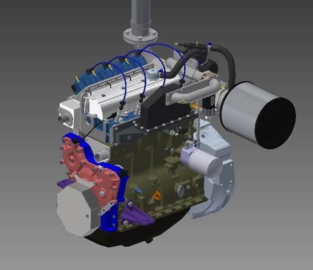
Figure 33 Effect of the compression ratio on the Brake Torque curves of the gas engine ........... 57
Figure 34 Effect of the compression ratio on the fuel consumption of the gas engine ................ 57
Figure 35 AFR of each case simulated of the gas engine ............................................................... 59
Figure 36 Effect of the AFR on the Brake Power curves of the gas engine.................................... 59
Figure 37 Effect of the AFR on the torque curves of the modified gas engine .............................. 60
Figure 38 Effect of the AFR on the Fuel Energy Entering Cylinder curves of the gas engine ........ 61
Figure 39 Effect of the AFR on the Throttle Angle curves of the gas engine ................................. 61
Figure 40 Effect of the AFR on the Brake Specific Fuel Consumption curves of the gas engine ... 61

LIST OF TABLES

Table 1 Engine type designation breakdown ................................................................................... 5
Table 2 Sisudiesel 420 DWRIE engine specifications ....................................................................... 6
Table 3 Diesel fuel requirements ..................................................................................................... 7
Table 4 Natural gas typical composition ........................................................................................ 14
Table 5 Properties of CNG, diesel and gasoline ............................................................................. 15
Table 6 Limit values for Wobbe Index and Methan Number ......................................................... 16
Table 7 Main gas engine characteristics compared to the original Sisudiesel engine................... 30
Table 8 Values of compression ratio according to the thickness of the installed gasket .............. 32
Table 9 Main gas engine parameters related to compression ratio reduction (see Appendix I). . 33
Table 10 Turbocharger modelling parts ......................................................................................... 38
Table 11 Intercooler modelling parts ............................................................................................. 40
Table 12 CNG reference object ...................................................................................................... 46
Table 13 CNG composition inputted in the model ........................................................................ 46
Table 14 Knocking monitoring object ............................................................................................ 48
Table 15 Range of compression values to be simulated ................................................................ 55
Table 16 Range of AFR values and their percentage difference to the stoichiometric value to be
simulated ........................................................................................................................................ 58
GLOSSARY

AFR Air-fuel ratio

BSFC Brake Specific Fuel Consumption

CI Compression Ignition

CNG Compressed Natural Gas

CR Compression Ratio

DI Direct Injection

ECU Electronic Control Unit

GHG Greenhouse gases

IC Internal Combustion

IDI Indirect Injection

LNG Liquified Natural Gas

LPG Liquified Petroleum Gas

MN Methane Number

NG Natural Gas

SI Spark Ignition

SPFI Spark Plug Fuel Injector

TDC Top Dead Centre

WI Wobbe Index
1

1. Introduction

Internal combustion (IC) engines powered by liquid fuels are currently the main propulsion
system in road transport (Serrano, et al., 2019) being responsible for about 10% of the world’s
greenhouse gas emissions (GHG). Moreover, they emit NOx and particulate matter which causes
bad air quality in cities. Thus, in the last years, it has been a goal for researchers to mitigate the
environmental impact of road transport, by reducing fuel consumption and emissions of the IC
engines (Reitz, et al., 2020). Besides, the reputation of IC engines, and particularly diesel engines,
has been compromised by emission scandals (Baumgärtner & Letmathe, 2020). For these reasons,
several EU countries presented legislation plans to prohibit IC engines in their markets, and
advocate for a transition to full electric mobility by 2040 (Wappelhorst, 2020). Likewise, some car
companies such as Ford, Volvo, or Jaguar have already announced their intentions to only sell
electric vehicles by 2030 in Europe (Frangoul, 2021).

Future trends in the transport sector are evidently inclined to electric mobility, but some
challenges need still to be faced, such as battery technology or the recharging infrastructure
(Chala, et al., 2018; Ghosh, 2020). And at this moment, the IC engine seems the more convenient
option not only for road transport but also for a range of applications such as industrial usages
(Reitz, et al., 2020). So, it is difficult to have a rapid transition from the traditional diesel and
gasoline IC engines to fully electric mobility.

This evidences the need for a transition technology before the total implementation of electric
mobility. A technology that can satisfy the applications for which IC engines are currently used
and at the same time contributes to reducing GHG, NOx and particulate matter emissions. In this
line, the use of alternatives fuels for powering IC engines can play a major role. For instance,
natural gas is the fossil fuel that produces the lowest GHG emissions and the minimum level of
suspended particles (Chala, et al., 2018). So, the implementation of these fuels in the current IC
engines will provide a technology that enables extending the existing engines’ life and avoids
them being dismissed because of their emissions. Consequently, it is highly convenient to study
and develop feasible, simple, and economical procedures to convert the existing engines to
operate with these alternative fuels.
2

This thesis focuses on the case of implementing alternatives gaseous fuels, also known as fuel
gases. Novia University of Applied Sciences, based in Vaasa (Finland), currently has a diesel engine
(Sisudiesel 420 DWRIE) in the laboratory. It is used for simulation and analysis purposes. Then, if
it had an engine powered by gas it would be possible to conduct investigations with this fuel. So,
given the research and investigation interest in alternative fuels, it is desired to convert this
existing diesel engine to operate with alternative fuel gas.

Therefore, this thesis aims to explore the possibilities of converting the laboratory diesel engine
to a gas engine. The thesis defines a feasible engine concept so that the laboratory engine can
fully operate on the previously selected appropriate gaseous fuel. It also models and simulates in
GT-Power software the proposed gas engine.
3

2. Aims and objectives

The aim of this thesis is to evaluate which is the optimum solution when implementing a
dedicated fuel gas engine in Novia UAS’ laboratory - it is relevant to note that it is requested a
gaseous type of fuel. The lab currently has a Sisudiesel engine, and it will be debated which is the
best option to modify it to operate on fuel gas.

To achieve the aim of this thesis, the following objectives are defined:
 • Analyse the existing engine in the laboratory and define how could be restructured to
 work with fuel gas.
 • Research the available fuel gases that can be used in an internal combustion engine to
 decide which one fits better.
 • Explore and compare diverse engine concepts and modifying strategies to adapt the lab
 engine to a dedicated fuel gas engine.
 • Simulate the selected concept with the software GT-power simulation tool and evaluate
 how different parameters influence the engine performance.
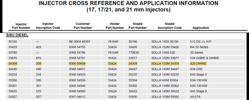
4

3. Review of literature

3.1. Sisudiesel 420 DWRIE engine

The available laboratory engine in Novia UAS’ laboratory to be converted to work on gas is a
Sisudiesel engine. Specifically, the engine is called Sisudiesel 420 DWRIE and it is located in the
Energy Technology and Automotive Technology laboratory in the basements of the
Technobothnia building in the Finnish city of Vaasa. In section 3.1.2 is undertaken an analysis of
this engine to know its designations and specifications.

3.1.1. AGCO Power Inc.

Sisu Diesel Inc. was the name of the company currently called AGCO Power Inc. from 1994 to 2009
(Porssitieto, 2021). This company have had different names since its first establishment in Siuro,
Nokia, Finland, in 1942. Back then, the company goal was to repair and manufacture some aircraft
parts and engines – it was the second-largest Finnish aircraft engine factory.

After the end of World War II, the company shifted its aircraft objectives towards developing,
designing, and producing diesel engines, which is still the company aim. Nowadays the current
company name is AGCO Power Inc., and it mainly develops diesel engines, highlighting three, four,
six and seven-cylinder diesel engines for tractors, diesel marine engines and diesel power
generation solutions (Agco Power, 2020).

According to Statista (2020), a distinguished German company specialized in the market and
consumer data, Argo Power Inc. employed more than 21,000 people and had a financial turnover
of 7,54 million euros by the end of 2020 – the latest year with available data. The company exports
worldwide having 3,250 dealers around the world. Their current portfolio includes the
manufacturing of tractors, combine harvesters, smart farming, and grain storage, among others
(Agco Power, 2020).

The diesel engine from Novia UAS’ laboratory to be converted to fuel gas was manufactured by
Sisu Diesel Oy company.
5

3.1.2. Sisudiesel 420 DWRIE specifications

According to the plate in the Sisudiesel engine from Novia UAS’ laboratory, the name of the
engine model to be evaluated and studied is Sisudiesel 420 DWRIE (Figure 1). This type of engine
is used mainly to supply tractors. The engine designation indicates the main characteristics of the
engine, and they are summarized in Table 1. The engine specifications are indicated in Table 2.

Table 1 Engine type designation breakdown (Sisu Diesel Inc., 2002)

 4 4 cylinders
 20D Basic type (not ECU)
 W Turbocharged engine equipped with bypass turbo
 R Rotary fuel injection pump
 I Equipped with intercooler air to water
 E Emission tested engine (certified) for off-road

From Table 1, it has to be highlighted that the engine does not equip an ECU (Electronic Control
Unit) and that it is designed and certified for off-road applications.

Figure 1 Drawing of Sisudiesel 420 DWRIE (Sisu Diesel Inc., 2002)
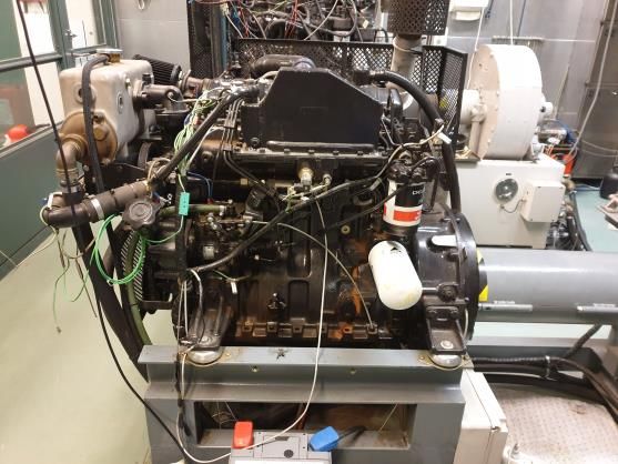
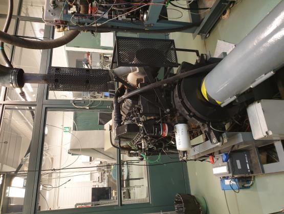
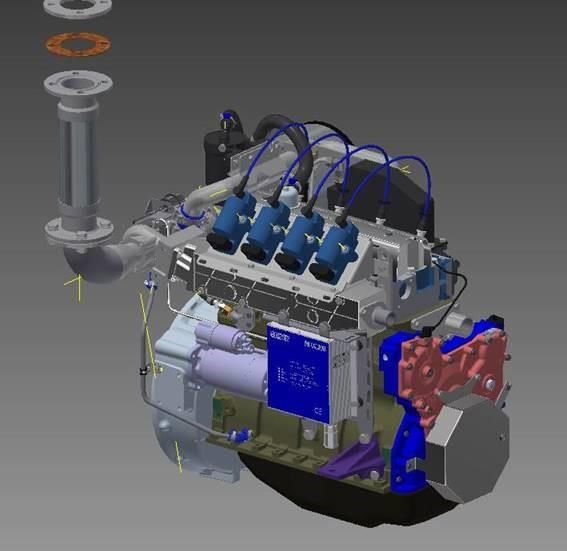
6

Table 2 Sisudiesel 420 DWRIE engine specifications (Sisu Diesel Inc., 2002)

 Manufacturer SISU Diesel Inc. (FINLAND)
 Type Sisudiesel 420 DWRIE
 Power 95 kW at 2200 rpm
 Serial nº J18570
 Displacement (dm3) 4.4
 Cylinder bore (mm) 108
 Stroke (mm) 120
 Compression ratio 16.5
 Combustion Direct injection
 Firing order 1-2-4-3
 Compression pressure (bar)1 24
 Weight (kg)2 345
 Direction of rotation from the engine front clockwise
1
) Minimum value at operating temperature and starting revs. Max permitted difference between cylinders 3,0 bar.
2
) Without flywheel and electrical equipment.

This diesel engine was initially designed as a tractor engine and subsequently assembled in the
laboratory for academic purposes. It has direct injection (DI) without a common rail. And
according to the engine plate, it has an output of 95 kW (approx. 130 hp) at 2200 rpm.

Figure 2 shows the set-up of the lab Sisudiesel 420 DWRIE engine in the Energy Technology and
Automotive Technology laboratory of Novia UAS.

Figure 2 Different views of lab Sisudiesel 420 DWRIE
7

Notice the plentiful space both on the sides and above the engine that potentially could allow
assembling all the possible necessary parts to convert the Sisudiesel engine to a dedicated fuel
gas engine.

3.1.3. Diesel

Diesel – also known as gasoil or diesel oil – is the typical fuel used in diesel engines and, therefore,
used in the Sisudiesel 420 DWRIE. It is obtained through crude oil distillation, it boils in the range
of 175-345⁰C and consists basely of hydrocarbons in the liquid state with ignition values of
approximately 350 ⁰C (Schobert, 2014).

According to Bosch (2014), high-quality types of diesel have the following peculiarities and
attributes taking into account their service life and that the fuel-injection systems work in a
constant function: high cetane number; moderately low final boiling point; low sulphur content;
narrow density and viscosity spread; low aromatic compounds content; good lubricity; absence
of free water; and restricted pollution with particulate.

Table 3 specifies the most relevant automotive diesel fuel requirements according to the
European Committee for Standardization (2009).
Table 3 Diesel fuel requirements (European Committee for Standardization, 2009)

 Standard Unit Parameter
 Cetane number - ≥ 51
 Cetane index - ≥ 46
 Density at 15°C kg/m3 820-845
 PAH1) % by mass ≤ 11
 Sulphur content mg/kg ≤ 102)
 Flash point °C ≥ 55
 Total contamination mg/kg ≤ 24
 FAME content3) % by volume ≤7
 Lubricity µm ≤ 460
 Viscosity at 40°C mm2/s 2-4,5
1
 ) Polycyclic aromatic hydrocarbons which are defined as the total aromatic hydrocarbon content less the mono-
aromatic hydrocarbon content.
2
 ) EU proposal to have what is considered sulphur-free from 2009.
3
 ) Fatty Acid Methyl Ester content.
8

3.2. Review of available fuel gases

According to the scope of this thesis – see aims and objectives in section 2 –, from Novia UAS’
laboratory it is solicited to implement in the engine a gaseous type of fuel, which will be called
fuel gas from now on.

As a fuel gas, it is understood a propellant that enters the engine in the gaseous phase although
may be stored as a liquid to facilitate its storage. Therefore, CNG (Compressed Natural Gas) would
enter the thesis’ scope but for instance, biodiesel or alcohols do not. That is an important fact
because a big delimitation of the fuels to be studied is made beforehand. Accordingly, it has been
agreed that it will be studied the following fuel gas alternatives: biogas, natural gas (or
biomethane) with its different storage forms, and liquified petroleum gas.

In order to achieve a good selection concerning the fuel gas that will be implemented in the
laboratory engine, it will be broadly taken into account the supply and availability adequacy of
the fuel gas; its ease of transport and safety of storage; the modifications needed in the engine;
the engine efficiency; and the fuel gas compatibility with the engine (power, emissions, ease of
use and durability of the engine). All these criteria based on Kumar (2018) and Ramadhas (2011)
will be considered in the following subchapters.

3.2.1. Main characteristics of fuel gases

From the considered fuel gases, their main characteristics are discussed to see whether they are
suitable for their implementation on the engine object of study.
9

3.2.1.1. Biogas

Biogas is a gas mainly composed of methane (40-75%) and carbon dioxide (15-60%). It can also
contain traces of water vapour, N2, O2, H2, H2S (Ryckebosch, et al., 2011). It is obtained from the
anaerobic digestion of biomass.

The gas quality requirements for an engine are strict. For example, high water or H2S content
imply corrosion (Wellinger & Lindberg, 2005) or high content of CO2 can imply a lower calorific
value (Ryckebosch, et al., 2011). So, it is not recommended to use raw biogas as an engine fuel.
Instead, as suggested by Wayan Surata, et al. (2014) it must be improved before upgraded.

Nevertheless, the company Scania (2018) tested using raw biogas – without refining or upgrading
– in their engines, but this is at a very experimental stage.

3.2.1.2. Natural gas and biomethane

Natural gas (NG) is a complex mixture of hydrocarbons in a gaseous state. It is primarily formed
by methane (80-98%), but usually, it also includes ethane, propane, higher hydrocarbons, and
other non-combustible gases (nitrogen, carbon dioxide) (Finnish Standards Association, 2017b).
Regarding biomethane, according to Ryckebosch, et al. (2011) it is a gas composed principally of
methane (95-97% CH4 and 1-3% CO2). It differs from natural gas because of its source.
Biomethane can be obtained from the upgrade of biogas or methanation of bio-syngas (Finnish
Standards Association, 2017a).

Natural gas and biomethane differ only on their source. As stated by IEA (2020), biomethane is
indistinguishable from natural gas and compatible with natural gas vehicles (Chandra, et al.,
2011). So, from now on, natural gas and biomethane will be named indistinctly.

Natural gas can be used as engine fuel for IC engines. However, according to the literature, lower
engine performance is expected. Chandra, et al. (2011) observed, in comparison with diesel, a
31.8% power loss in the modified IC natural gas engine. Semin, et al. (2009b) concluded that a
10

modified gas engine implied a reduction in torque performance and Bari & Hossain (2018) also
reported engine performance reduction. Moreover, a dedicated natural gas engine needs to have
an ignition system such as spark ignition (SI) (Ramadhas, 2011; Chala, et al., 2018).

Due to natural gas low density, it is usually stored as CNG (Compressed Natural Gas) or LNG
(Liquified Natural Gas) (Reif, 2015).

Compressed Natural Gas (CNG)

Natural gas can be stored in gaseous form at ambient temperature under high pressure
(Ramadhas, 2011). It is compressed up to 200 - 248 bar (Imran Khan, et al., 2015) to obtain CNG
– or compressed biomethane. Before handling it to the engine, it is converted to atmospheric
pressure.

Liquified Natural Gas (LNG)

Natural gas and biomethane can also be stored in liquid form and atmospheric pressure. Liquified
natural gas and liquified biomethane are obtained when they are cooled at cryogenic
temperatures, about -161°C, and stored at atmospheric pressure (Ramadhas, 2011). LNG has a
higher energy content per unit volume than CNG, but it presents more difficulties in storage.
Although LNG tanks are well insulated, heat leaks into the tank and LNG start to evaporate. For
this reason, LNG cannot be permanently stored (Go With Natural Gas, 2014). Furthermore, LNG
has a higher cost of production and storage (Semin, et al., 2009a).

3.2.1.3. Liquefied Petroleum Gas

Liquefied petroleum gas (LPG) can be obtained from different sources such as natural gas
purification, oil fields or as a by-product of petroleum refining. It consists of condensed butane
(C3H8) and propane (C4H10) gases, with configurations for automotive fuel about 70% of butane
and 30% of propane however, it depends on the composition stipulated in each country
(Ramadhas, 2011).
11

Characteristics that make LPG a fuel suitable for internal combustion engines are its high-octane
number – good for spark-ignited engines –, the possibility of transport and storage in the liquid
state, lower cost per energy than gasoline, and fewer GHGs emissions.

Regarding LPG use in vehicles, according to Ramadhas (2011), it can be used both in spark ignition
and compression ignition (CI) engines. In the case of SI engines, there is the possibility to convert
them to dedicated LPG fuelled engine since LPG behaves very similarly to gasoline when injected
into cylinders. On the other hand, in the case of CI engines, the solution is to perform in a dual
fuel mode operation, where it is injected a mixture of LPG and air and a small amount of diesel
called pilot that allows the auto-ignition (Ashok, et al., 2015).

3.2.2. Fuel availability

From the viable fuel gases to implement in the engine, it is discussed their availability.

Finland has a developed industry of biogas production (Gasum, 2021b; Bioenergia, 2021) with 63
biogas production plants and an annual production greater than 100 hm3 in the year 2017
(Winquist, et al., 2019).

Natural Gas in Finland is imported – mainly from Russia – or produced by improving biogas
(Gasgrid, 2021). There are numerous CNG stations as can be seen in Figure 3. For instance,
Stormossen is a company based in the Vaasa region that produces CNG by improving biogas.
BIG-BIOGAS is the company that sells Stormossen gas and has two CNG filling stations within 10
km of Vaasa city centre (STORMOSSEN, 2021).
12

 Figure 3 Map of CNG stations in Finland (Gasum, 2021b) Figure 4 Map of LNG stations in Finland - yellow
 highlighted (Gasum, 2021a)

Some LNG stations can be found in Finland, as shown in Figure 4. But there are not so many
stations as in the case of CNG. Moreover, the nearest station from Vaasa is about 80 km far.

Regarding LPG, it is not such an implemented fuel as natural gas in Finland (Salles, et al., 2019).
Thus, there is not a developed LPG station network. However, it has been found that the company
Teboil (2020) supplies LPG in little gas bottles, cylinders or tanks for companies or households.

3.2.3. Fuel gas selection

Biogas contains many impurities (Ryckebosch, et al., 2011) that can have bad consequences for
gas infrastructure and the engine. Thus, it is not recommended to use untreated biogas in
engines. For this reason, it is discarded as a possible fuel for being implemented in the engine
object of study.
13

Although LPG is a fuel widely used for its properties and its possibilities of transport (Ramadhas,
2011), its uncommon supply in Finland – see section 3.2.2 – makes it not preferential for the
chosen gaseous fuel.

In the case of LNG, it presents some difficulties in storing it permanently. The use of the engine,
as a lab test engine, means that LNG would not be regularly consumed. So, for this reason, this
fuel is dismissed as a suitable fuel for the lab engine.

So, for the arguments considered in sections 3.2.1 and 3.2.2, it is concluded that CNG is the more
suitable fuel for implementing in the engine object of study of the present thesis, both for its
characteristics and availability. It is suitable for the engine specifications and also widely available
and locally produced in Finland.

3.2.4. Compressed Natural Gas

Compressed Natural Gas is natural gas that has been compressed to facilitate its storage. When
stored it has a gaseous state, with pressures between 100 and 250 bar and temperatures between
-40 to 30 °C (Chala, et al., 2018).

Natural gas

Natural gas is a gaseous mixture mainly composed of methane (CH4), but it also contains certain
amounts of ethane, propane, nitrogen, helium, carbon dioxide, hydrogen sulphide and water
vapour. Natural gas varies in composition by location, season or even through the transmission
network (Semin, et al., 2009c). However, a typical composition can be attributed to natural gas
as seen in Table 4.
14

Table 4 Natural gas typical composition (Speight, 2015)

Constituent Formula Typical values (% v/v)
Methane CH4 70–90
Ethane C2H6 0–5
Propane C3H8 0–5
Butane C4H10 0–5
Pentane C5H12 0–5
Hexane (and higher) ≥C6H14 Trace–5
Benzene (and higher) ≥C6H6 Trace
Carbon dioxide CO2 0–8
Oxygen O2 0–0.2
Nitrogen N2 0–5
Hydrogen sulphide H2S 0–5
Rare gases He, Ne, A, Kr, Xe Trace
Water H2O Trace–5

Table 4 shows that despite methane being the main component of natural gas, it can take a wide
range of values of percentage by volume (from 70 to 90).

Natural gas properties

Natural gas properties play an important role in the different processes involved in the IC engine
as mixture formation, ignition, and combustion. Table 5 shows a range of properties of CNG
compared to traditional liquid fossil fuels Diesel and Gasoline.
15

Table 5 Properties of CNG, diesel and gasoline (Chala, et al., 2018)

 Properties CNG Diesel Gasoline
 CH4 (83–99%)
 Chemical formula C3 to C25 C4 to C12
 C2H5 (1–13%)
 Carbon 75 87 85–88
 Composition by weight [%]
 Hydrogen 25 30 12–15
 Molecular weight [g/mol] 16.04 200 100–105
 Density @15.5 °C [kg/m3] 128 848 719–779
 Molar Basis 9.7 50.03 59.5
 Stoichiometric air-fuel ratio
 Mass Basis 17.2 14.7 14.7
 Auto ignition temperature [K] 813.15 588.7 530.37
 Research octane number (R) >127 N/A 90-100
 Octane number Motor octane number (M) 122 N/A 81-90
 Mean (R+M)/2 >120 N/A 86–94
 Cetane number N/A 40-55 5-20
 Boiling temperature @atmospheric pressure [°C] −164 to −88 180–340 27–225
 Flammability of fuel - gas mixture [%] 5.3–15.0 1.0–6.0 1.4–7.6
 Lower calorific value [MJ/kg] 47.13 42.78 43.44

The stoichiometric Air-Fuel Ratio (AFR) indicates the minimum amount of air needed for the
complete combustion of the fuel (Çengel & Boles, 2014). Mass stoichiometric AFR for natural gas
is 17.2, higher than in the case of diesel and gasoline.

Calorific value is the amount of energy released when a unit of mass of fuel reacts with oxygen in
a combustion process (Mohamad, 2006). The calorific value of natural gas is higher than the value
for gasoline and diesel.

Natural gas has a higher-octane number (127) when comparing it to gasoline (90-100). This means
that natural gas is more resistant to the knocking phenomenon (Semin, et al., 2009c).

Flammability indicates the capacity of a fuel-air mixture to produce a flame that can propagate
through the unburned mixture (Gardiner, et al., 2008). Flammability limits are the fuel
concentration limits within the mixture is flammable. As seen in Table 5, these limits are higher
for natural gas, which means it is less flammable than diesel or gasoline. In this line, Mohamad
16

(2006) suggests that, in IC engines, the ignition must be advanced earlier to ensure complete NG
combustion.

Compared with Diesel, the higher autoignition temperature and the much lower cetane number
indicate that natural gas requires higher ignition energy.

As stated, natural gas can vary in composition. Thus, two parameters allow defining and
characterizing each specific natural gas. They indicate gas interchangeability and compatibility.
These are the Wobbe Index (WI) and Methane Number (MN). The WI represents the heating value
of the natural gas and it is determined by its composition. The MN is a measure used for the knock
rating of gaseous fuels (Malenshek & Olsen, 2009). The European Standard EN 16723-2:2017
establish limit values for these two parameters as automotive gaseous fuel specifications. They
are listed in Table 6.

Table 6 Limit values for Wobbe Index and Methan Number – adapted from Finnish Standards Association (2017a)

 Required values Recommended values
 Parameter
 Minimum Maximum Minimum Maximum
 Wobbe Index (MJ/Sm3) inferior - - 41.9 49
 Methane Number 65 - 70 -
17

3.3. Engine modifications to operate on natural gas

In this section, it will be studied which modifications require a diesel engine to work on natural
gas, according to the gas properties analysed in section 3.2.4, and how can they be implemented.

3.3.1. Natural gas engine requirements

According to the literature, there has been identified a set of modifications that need to be made
to a diesel engine to operate with natural gas. These are:
 1) Installation of an ignition system
 2) Reducing the compression ratio
 3) Installation of fuel supply and mixing system

Firstly, regarding natural gas properties exposed in section 3.2.4, it is necessary to have an ignition
system (Chala, et al., 2018). This is due to the natural gas high autoignition temperature, which
implies that it gas cannot be ignited by compression, as it is done in a diesel engine (Reif, 2014).

Knocking is a phenomenon that must be avoided in engines. Having low compression ratios (CR)
tends to avoid this phenomenon, but at the same time, low CR reduces engine performance and
efficiency (Aina, et al., 2012; Gnanamoorthia & Devaradjaneb, 2015). Natural gas does not require
so low a compression ratio as gasoline (Reif, 2015) because it is more resistant to knocking (see
3.2.4). Nevertheless, the pressures reached in the diesel engine will be too high for operating on
natural gas. So, according to Siripornakarachai & Sucharitakul (2007), to ensure proper
combustion and avoid knocking, the pressure in the cylinder chamber needs to be reduced. In
this line, von Mitzlaff (1988) suggested the reduction of compression ratio to 12 or less while
Ramadhas (2011) stated that the compression ratio needs to have a value between 10 and 13,
and Kumar (2018) opted to maintain the compression ratio within 9 and 13. Moreover, another
modification to avoid knocking could be reducing the turbocharger pressure.
18

It is also necessary to replace the diesel injection system, with a supply system suitable for CNG.
This system must be able to obtain an accurate air/gas mixture and supply it to the combustion
chamber (von Mitzlaff, 1988).

3.3.2. Possible diesel engine modifications to operate on natural gas

This section explores the possible modifications that can be applied to the engine object of study
to meet the requirements of a gas engine, exposed in section 3.3.1.

3.3.2.1. Ignition system

As stated, a natural gas engine requires an ignition system (Reif, 2015). Many authors such as
Kumar (2018) or von Mitzlaff (1988) suggest implementing spark plugs to ignite the mixture, a
system very similar to those found in gasoline engines. As the engine has four cylinders, it will be
necessary to implement an ignition distributor system connected to the camshaft or the gear
drive. Besides, with spark ignition, the air-fuel mixture must be close to stoichiometric (Stone,
2012).

Some authors also propose using another fuel to ignite the air-gas mixture, a system which is
known as pilot injection (Prasad, et al., 2019; Xiang, et al., 2020). This concept would require using
an air gas lean mixture. Besides, it would imply having to fuel systems – natural gas and diesel –,
increasing the engine complexity.

3.3.2.2. Compression ratio reduction

Different methods can be applied to reduce the compression ratio. They essentially focus on
increasing the cylinder clearance volume.
19

Piston modification

One method is to machine off material from the piston. By milling the piston head, a bowl shape
can be created. Apart from increasing the volume, this resulting geometry helps to obtain a
proper natural gas and air mixture (Shinde, 2012). Even that, this process could alter the dynamic
balance in the engine. Moreover, the machining must be accurate for the cylinder head not to
become so thin (von Mitzlaff, 1988).

Connecting rod modification

Another possibility is to modify the length of the connecting rod. By reducing its length, the
cylinder volume will increase, resulting in a lower compression ratio. Nevertheless, according to
Kumar (2018), this method can be very costly. And an imprecise design can cause vibration and
thermal stress to the piston.

Cylinder head gasket

The literature also suggests replacing the cylinder head gasket with a thicker one (Krishna, 2018;
Kumar, 2018). This would enlarge the combustion chamber. An equivalent option suggested by
Siripornakarachai & Sucharitakul (2007) is to add a plate known as a head spacer, similar to having
two head gaskets. Both options do the same function but having a gasket plus a spacer may
increase the risk of leakage. Anyway, these solutions rely on the availability of these parts or the
feasibility of manufacturing them.

Cylinder head exchange

Von Mitzlaff (1988) also proposes to exchange the cylinder head for one that offers a higher
combustion chamber volume, as an optimal method. However, it is subject to the availability of
this part.
20

3.3.2.3. Fuel supply and mixing system

For the gas supplying system, two different concepts are considered according to the literature.
One option is to install gas injectors in the cylinder head, supplied by a gas rail. The other option
is to implement a carburettor or an equivalent mixing device.

Gas injectors

The gas injectors concept is proposed by Kumar (2018). In this case, the gas is directed to the
common rail which supplies the injectors, and there is one injector for each cylinder (Reif, 2015).
Then, the mixture is formed in the intake manifold – indirect injection (IDI) – or in the combustion
chamber – direct injection (DI) – (Mohamad, 2010). This option requires fitting both the gas
injector and the ignition device in each cylinder. This means that the installation of injectors may
require a new cylinder head which could be bought, if available, or manufactured, with its
complex design.

To solve the problem of fitting both the injector and the spark plug one alternative solution is the
Spark Plug Fuel Injector (SPFI). This is a device that integrates both the injector and the spark plug,
as seen in Figure 5. It was developed as part of a Ph.D. Thesis (Mohamad, 2010), but it is at an
experimental stage, not being commercially developed.

Figure 5 Spark Plug Fuel Injector design (Mohamad, 2010)
21

Mixing device

With the mixing device option, there is no need to install injectors. The air-gas mixture is formed
in the mixing device before the intake port. So, no modifications would need to be done to the
cylinder head. But it must be verified if it is physically possible in terms of available space to install
this mixing device on the existing engine set-up. Besides, there are different options regarding
the mixing device.

A simple mixing chamber such as a T-junction could be used to mix natural gas and air (Kok & van
der Wal, 1996), in case the engine operates in steady conditions (von Mitzlaff, 1988). This means
at constant speed and load. But the laboratory engine may be run at different speeds.

Another option is a Venturi mixer, as suggested by many authors such as von Mitzlaff (1988),
Siripornakarachai & Sucharitakul (2007), Rodriguez Cussó (2013) or Sandfirden Technics (n.d.).
The Venturi mixer uses the same principle as the carburettor.

3.4. SGI-4 industrial gas engine – a case study

Industrial gas engine SGI-4 is an engine concept developed by the Dutch company Sandfirden
Technics. According to the personal correspondence with the company (12.4.2021), this new
engine is manufactured based on the existing Sisudiesel DWRIE 420 engine.

The company designs and manufactures new cylinders heads with the necessary modifications to
performance in natural gas. Moreover, some modifications are undertaken inside the pistons to
get the desired compression ratios. Figure 6 shared by the company, illustrates the Sandifirden
Technics engine which is quite similar to the lab Sisudiesel 420 DWRIE engine, however, an
influential alteration has been carried out.
22

Figure 6 Different views of Sandfirden Technics modified engine (personal correspondence with the company,
12.4.2021)

The main modifications in the cylinder head are based on helping the engine to achieve a lower
compression ratio and assembling a completely different injection system. As can be proved in
Figure 6, no more direct injection is undertaken, and diesel injectors have been replaced by spark
plugs since natural gas needs a spark to ignite. Instead, according to Sandfirden Technics (n.d.), a
mixer type called Motortech VariFuel is used to blend the air and the natural gas in a manner
analogous to the use of a carburettor in some liquid-fuelled engines.

Therefore, Sandfirden Technics has successfully achieved to modify existing Sisudiesel engines to
work in fuel gas which can be considered a good inspiration for the present thesis.
23

4. Natural gas engine concept

4.1. Proposed strategies and concepts

In section 3.3.2, the required modifications for obtaining a gas engine are presented and different
options to implement these modifications are discussed. These modifications need to be
considered as a whole. Thus, three different possible engine concepts and modification strategies
are proposed:
 1) CNG SI engine with DI and the existing cylinder head
 2) CNG SI engine with DI and a replaced cylinder head
 3) CNG SI engine with air-mixing device

Figure 7 gives a picture of the available possibilities for converting the Sisudiesel engine to a
dedicated fuel gas engine according to the reflections of section 3.3.2.

 POSSIBLE MODIFYING
 STRATEGIES AND
 ENGINE CONCEPTS

 CONCEPT 1 CONCEPT 2 CONCEPT 3
 Take advantage of the Replace the cylinder head Assemble a mixing device
 existing holes in the for one that can fit the and replace the existing
 cylinder head to set spark spark plugs and gas injectors with spark plugs
 plugs and gas injectors injectors

 Potential space Benchmark the
 problems to fit market alternatives - Remove the direct
 everything get a cylinder head of injection system
 the same size

 Develope a new
 design

Figure 7 Decision diagram for engine modifying strategies and concepts

Throughout the current section, Figure 7 contents will be developed and discussed to achieve an
optimal concept of dedicated fuel gas engines.
24

4.1.1. Concept 1. SI engine with DI and the existing cylinder head

Regarding the engine concept, the first strategy implies an SI engine equipped with a natural gas
injection system with a common rail.

In the proposed strategy, the cylinder head is not replaced. Therefore, a head spacer should be
installed to enlarge the combustion chamber and reduce the compression ratio. The thickness of
this head spacer or gasket should be estimated and a market analysis carried out to obtain if it is
manufactured. Otherwise, it would be possible to design and manufacture in detail a brand-new
gasket in the university implying a high complexity level and demand which is out of the scope of
this thesis.

The whole diesel injection system should be substituted for a gas injection system with common
rail therefore the diesel injectors should be removed. As the cylinder head is not replaced, it
should be managed to accommodate the new gas injectors and the spark plugs with the space
left. And this is the point that would represent the greatest challenge.

Figure 8 shows the section of the Sisudiesel engine with the diesel injector.

Figure 8 Section of the Sisudiesel engine with the injector yellow highlighted (Sisu Diesel Inc., 2002)
25

As seen in Figure 8, the injector highlighted in yellow is the one that requires replacement for
both a spark plug and a gas injector. However, the existing injector holder body diameter is 21
mm (see Figure 9).

Figure 9 Sisudiesel 420 DWRIE injector holder body diameter – adapted from Stanadyne (2007)

Therefore, is evident that it is no viable to fit a spark plug and a gas injector in the existing diesel
injector diameter. To demonstrate it, Figure 10 shows graphically the three diameters
superimpose. The spark plug diameter corresponds to the model CNG/LPG Laser Line
commercialized by the dealer NGK (2019) with a diameter of 14 mm. The gas injector is the Fuel
Injector High Impedance Gas Petrol Methanol from the dealer Bosch (Bsuplemen, 2021) with a
body diameter of 16 mm. Notice that thorough market research for the most feasible gas injector
and spark plug has not been carried out since the objective is only to figure out the physical
problem of space availability.
26

Figure 10 Impossibility to fit the spark plug and the gas injector in the existing diesel injector hole

Therefore, according to Figure 10, it is clear that there is no chance to fit the gas injector and the
spark plug in the existing hole.

An alternative option could be the SPFI, which integrates both the spark plugs and injectors in a
device (see section 3.3.2.3). But this part is at an experimental stage and it is not available in the
market.

Finally, there are other points to focus on as well for instance the assembly of the gas common
rail or the supply pump however, since it is a lab engine there would not be space problems to
piecing together all that components.

Consequently, it is deemed this strategy to be not feasible to implement in the lab engine mainly
for the impracticability to take advantage of the existing cylinder head for fitting both the spark
plugs and gas injectors.

4.1.2. Concept 2. SI engine with DI and replaced cylinder head

In this case, the engine concept is the same as in the previous strategy. It is a SI engine with a
natural gas injection system with a common rail.
27

The existing cylinder head is to be replaced. An appropriate new cylinder head could satisfy
multiple requirements needed for the engine operation on gas. Firstly, it would allow having a
larger combustion chamber, to obtain the desired compression ratio. Thus, there would be no
need to add a head spacer. Secondly, the cylinder head could be designed to accommodate at
the same time the spark plugs and the gas injectors. Moreover, the combustion chamber shape
could be optimised to facilitate the air-gas mixture combustion.

This strategy requires having an appropriate cylinder head, which could be bought or designed
and manufactured. Regarding the first option, it has been found that the company Sandfirden
Technics (2020) has got modified cylinder heads for the Sisudiesel engine. These cylinder heads
are specifically designed for engine operation on gas, but with a different engine concept (see
section 3.4). Consequently, these cylinder heads are not adapted to lodge gas injectors.
Furthermore, it has not been possible to verify its availability on the market.

This leads to the second option, to design and manufacture a new cylinder head. Designing such
a complex part would imply a complex process, which is out of the scope of the present thesis.

So, for the unavailability of market supply of an adequate cylinder head, and the complexity of
designing and manufacturing one, it is considered that this strategy is not effective for modifying
the engine to operate on natural gas.

4.1.3. Concept 3. SI engine with mixing device

This strategy envisages an engine concept consisting of an SI engine with a Venturi mixer – gas
mixer – as the natural gas supplying system. Thus, the obstacle of assembly of both the spark plug
and gas injector in the existing diesel injector hole is dismissed.

In this case, the cylinder head is not replaced. Therefore, a head spacer should be installed to
enlarge the combustion chamber and reduce the compression ratio. A gas mixer would be
installed and since the air-gas mixture would be carried out there, all the current injection system
should be disassembled. Thus, the existing diesel injectors would be removed, and the space left
You can also read