Fused Filament Fabrication of Polymers and Continuous Fiber-Reinforced Polymer Composites: Advances in Structure Optimization and Health ...

Page created by Gerald Powell
 
CONTINUE READING
Fused Filament Fabrication of Polymers and Continuous Fiber-Reinforced Polymer Composites: Advances in Structure Optimization and Health ...
polymers
Review
Fused Filament Fabrication of Polymers and Continuous
Fiber-Reinforced Polymer Composites: Advances in
Structure Optimization and Health Monitoring
Fatemeh Mashayekhi, Julien Bardon                     , Vincent Berthé, Henri Perrin          , Stephan Westermann
and Frédéric Addiego *

                                          Department Materials Research and Technology (MRT), Luxembourg Institute of Science and Technology (LIST),
                                          ZAE Robert Steichen, 5 Rue Bommel, L-4940 Hautcharage, Luxembourg; fatemeh.mashayekhi@list.lu (F.M.);
                                          julien.bardon@list.lu (J.B.); vincent.berthe@list.lu (V.B.); henri.perrin@list.lu (H.P.);
                                          stephan.westermann@list.lu (S.W.)
                                          * Correspondence: frederic.addiego@list.lu; Tel.: +352-275-888-4639

                                          Abstract: 3D printed neat thermoplastic polymers (TPs) and continuous fiber-reinforced thermo-
                                          plastic composites (CFRTPCs) by fused filament fabrication (FFF) are becoming attractive materials
                                          for numerous applications. However, the structure of these materials exhibits interfaces at different
                                          scales, engendering non-optimal mechanical properties. The first part of the review presents a
                                          description of these interfaces and highlights the different strategies to improve interfacial bonding.
                                The actual knowledge on the structural aspects of the thermoplastic matrix is also summarized in
         
                                          this contribution with a focus on crystallization and orientation. The research to be tackled to further
Citation: Mashayekhi, F.; Bardon, J.;     improve the structural properties of the 3D printed materials is identified. The second part of the
Berthé, V.; Perrin, H.; Westermann, S.;   review provides an overview of structural health monitoring technologies relying on the use of
Addiego, F. Fused Filament
                                          fiber Bragg grating sensors, strain gauge sensors and self-sensing. After a brief discussion on these
Fabrication of Polymers and
                                          three technologies, the needed research to further stimulate the development of FFF is identified.
Continuous Fiber-Reinforced
                                          Finally, in the third part of this contribution the technology landscape of FFF processes for CFRTPCs
Polymer Composites: Advances in
                                          is provided, including the future trends.
Structure Optimization and Health
Monitoring. Polymers 2021, 13, 789.
https://doi.org/10.3390/
                                          Keywords: fused filament fabrication; thermoplastic polymer; continuous fiber-reinforced thermo-
polym13050789                             plastic composites; structure; interface; sensor; technology landscape

Academic Editor: Victor Tcherdyntsev

Received: 11 February 2021                1. Introduction
Accepted: 26 February 2021                      Continuous fiber-reinforced thermoplastic composites (CFRTPCs) have gained con-
Published: 4 March 2021
                                          siderable attention in automotive and aeronautics applications due to their attractive
                                          strength-to-weight ratio, enabling energy and recyclability to be saved as suitable end-of-
Publisher’s Note: MDPI stays neutral
                                          life scenario. The development of fused filament fabrication (FFF) by 3D printing tech-
with regard to jurisdictional claims in
                                          nology enables us to reduce lead time, accelerate design iteration, and fabricate complex
published maps and institutional affil-
                                          shape-eliminating sub-components [1]. The quest for printed parts with high mechanical
iations.
                                          performance led to the development of innovative FFF processes where continuous fibers
                                          are incorporated into printed structures [2,3]. The different thermoplastic polymer (TP)
                                          matrices and CFRTPCs that can be FFF-printed are reported in [4,5], including their process
                                          variables and the resulting tensile strength. For example, the tensile strength of neat TP
Copyright: © 2021 by the authors.         ranges from 34 MPa in the case of acrylonitrile butadiene styrene (ABS) to 100 MPa in the
Licensee MDPI, Basel, Switzerland.
                                          case of polyether ether ketone (PEEK). Concerning CFRTPCs, their tensile strength can
This article is an open access article
                                          reach several hundreds of MPa depending on the composite design, fiber content, and
distributed under the terms and
                                          fiber orientation, approaching that of aluminum under certain conditions [6]. 3D printed
conditions of the Creative Commons
                                          CFRTPCs appear very attractive, but the scale-up of this promising technology from the
Attribution (CC BY) license (https://
                                          prototyping to the production of finished functional components is not straightforward [4].
creativecommons.org/licenses/by/
                                          This may be attributed to the long build time and non-optimal mechanical properties of the
4.0/).

Polymers 2021, 13, 789. https://doi.org/10.3390/polym13050789                                            https://www.mdpi.com/journal/polymers
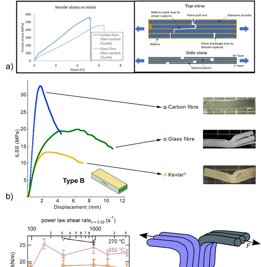
Fused Filament Fabrication of Polymers and Continuous Fiber-Reinforced Polymer Composites: Advances in Structure Optimization and Health ...
Polymers 2021,
Polymers       13, x789
         2021, 12,   FOR PEER REVIEW                                                                                                                22 of
                                                                                                                                                       of 29
                                                                                                                                                          28

                                 of the 3D printed materials, as highlighted in [7]. To address these issues, a better under-
                                  3D printed
                                 standing    of materials,    as highlighted
                                                the rheological      behavior of    in the
                                                                                        [7].TP
                                                                                             To may
                                                                                                 address
                                                                                                       be ofthese
                                                                                                               greatissues,    a better
                                                                                                                       help since     FFFunderstanding
                                                                                                                                            involves heat
                                 transfer from the extruder barrel to the TP, extrusion of the melted TP, shear heat
                                  of the  rheological   behavior       of  the  TP   may    be of  great   help  since     FFF   involves     and transfer
                                                                                                                                                    elonga-
                                  from   the extruder    barrel    to  the  TP,  extrusion     of  the melted     TP,   shear
                                 tion of the TP when entering the nozzle, and die swell of the TP when exiting the nozzle        and   elongation      of the
                                 TP when entering the nozzle, and die swell of the TP when exiting the nozzle [7–9]. The
                                 [7–9]. The rheological behavior of the TP is also expected to be drastically influenced by
                                  rheological behavior of the TP is also expected to be drastically influenced by the presence
                                 the presence of the continuous fibers during the printing process. In this review, we do
                                  of the continuous fibers during the printing process. In this review, we do not discuss the
                                 not discuss the recent advances in the rheology of the 3D printed materials, and rather
                                  recent advances in the rheology of the 3D printed materials, and rather point the readers to
                                 point the readers to an interesting review on this topic [7]. Instead, we focus on polymer
                                  an interesting review on this topic [7]. Instead, we focus on polymer and composite science
                                 and composite science and engineering approaches to understand and optimize the me-
                                  and engineering approaches to understand and optimize the mechanical properties of the
                                 chanical properties of the 3D printed materials.
                                  3D printed materials.
                                        The FFF of neat TPs and CFRTPCs leads to structures with interfaces at different
                                        The FFF of neat TPs and CFRTPCs leads to structures with interfaces at different
                                 scales that are detrimental for the mechanical properties when compared to the same ma-
                                  scales that are detrimental for the mechanical properties when compared to the same
                                 terials manufactured by traditional processes employing high pressures. For example,
                                  materials manufactured by traditional processes employing high pressures. For example,
                                 FFF-printed ABS reinforced with continuous carbon fibers exhibits a tensile strength of
                                  FFF-printed ABS reinforced with continuous carbon fibers exhibits a tensile strength of
                                 about
                                  about 150
                                          150 MPa,
                                              MPa, which
                                                     which is  is 33%
                                                                   33% lower
                                                                          lower than
                                                                                  than that
                                                                                          thatofofthe
                                                                                                   thesame
                                                                                                        samecomposite
                                                                                                                composite processed
                                                                                                                                processed by   by injection
                                                                                                                                                   injection
                                 molding     [10].  This   result   can    be  explained      by  the  presence       of
                                  molding [10]. This result can be explained by the presence of three types of interface  three   types    of interface    in
                                 the  FFF-printed
                                  in the  FFF-printedmaterials      engendering
                                                            materials      engendering non-optimal
                                                                                              non-optimalmechanical
                                                                                                                mechanical properties     [5,10–12].
                                                                                                                                  properties           First,
                                                                                                                                                  [5,10–12].
                                 the
                                  First, the literature reports the existence of nanoscale interfaces between two filling (also
                                      literature   reports    the   existence     of  nanoscale      interfaces    between       two   filling  lines   lines
                                 called   weld lines),
                                 (also called             involving
                                                 weld lines),            a non-optimal
                                                                   involving      a non-optimalpolymer      interchain
                                                                                                       polymer              diffusion.
                                                                                                                     interchain           Second,Second,
                                                                                                                                     diffusion.       FFF is
                                 characterized     by microscale
                                  FFF is characterized                 interfaces
                                                             by microscale            between between
                                                                                   interfaces     the impregnated          fiber bundle
                                                                                                               the impregnated          fiber(orbundle
                                                                                                                                                 towpreg) (or
                                 and    the  polymer     matrix,      linked     to  poor     polymer-fiber        adhesion
                                  towpreg) and the polymer matrix, linked to poor polymer-fiber adhesion or wettability.          or  wettability.      Last,
                                 mesoscale    interfaces
                                  Last, mesoscale           between
                                                      interfaces         each ofeach
                                                                     between        the four   filling
                                                                                           of the  fourlines    with
                                                                                                          filling      potentially
                                                                                                                   lines               a lack of bonding
                                                                                                                            with potentially       a lack of
                                 have   beenhave
                                  bonding     highlighted.     These interfaces
                                                    been highlighted.                   are represented
                                                                              These interfaces                in Figure in
                                                                                                    are represented         1aFigure
                                                                                                                                in the case
                                                                                                                                         1a inoftheneat
                                                                                                                                                     caseTPs
                                                                                                                                                           of
                                 and   in Figure   1b  in  the  case    of  CFRTPCs.       The   high   attractiveness
                                  neat TPs and in Figure 1b in the case of CFRTPCs. The high attractiveness of 3D printed    of  3D   printed    materials
                                 has  led to has
                                  materials   a significant     number of
                                                   led to a significant          research
                                                                              number          studies within
                                                                                          of research    studiesthe      last the
                                                                                                                    within    10 years
                                                                                                                                   last 10aiming      at im-
                                                                                                                                             years aiming
                                 proving    the  bonding      at  these    different    interfaces.   The    first  part   of this
                                  at improving the bonding at these different interfaces. The first part of this review provides     review    provides     a
                                 detailed
                                  a detaileddescription
                                               description   ofofthese
                                                                   thesethree
                                                                            threeinterfaces
                                                                                    interfacesand andexplores
                                                                                                        exploresthe  themost
                                                                                                                           mostefficient
                                                                                                                                   efficient methods
                                                                                                                                               methods to
                                 improve          interfacialbonding
                                  improve the interfacial         bondingbased basedonon     adhesion
                                                                                           adhesion        engineering,
                                                                                                       engineering,           printing
                                                                                                                          printing          optimization,
                                                                                                                                      optimization,      and
                                 and   material
                                  material        design
                                             design         optimization
                                                      optimization              (Figure
                                                                          (Figure    2). 2).

     Figure 1. Multiscale interfaces in 3D printed (a) neat TPs [5] and (b) CFRTPCs [10] (copyright (2017), with permission
     Figure 1. Multiscale interfaces in 3D printed (a) neat TPs [5] and (b) CFRTPCs [10] (copyright (2017), with permission from
     from Emerald Publishing Limited). Nanoscale and mesoscale interfaces are generated between two and four printing lines,
     Emerald Publishing Limited). Nanoscale and mesoscale interfaces are generated between two and four printing lines,
     respectively, and
     respectively, and microscale
                       microscale interfaces
                                   interfaces are
                                              are generated
                                                  generated between
                                                             between the
                                                                      the TP
                                                                          TP matrix
                                                                              matrix and
                                                                                     and the
                                                                                          the fiber
                                                                                               fiberbundle.
                                                                                                    bundle.

                                      If mechanical properties are of primary interest for structural applications requiring
                                 load-bearing capacity, the implementation of other functionalities can further increase
                                 FFF-printed materials’ attractivity and enlarge their application range. To this end, nu-
                                 merous functionalities have been developed as sensing, self-healing, magnetic properties;
Fused Filament Fabrication of Polymers and Continuous Fiber-Reinforced Polymer Composites: Advances in Structure Optimization and Health ...
and growing domain proves to be quite innovative and active. Our objective in the last
                         part of the review is to address the applied aspects of those developments by drawing the
                         current technology landscape of FFF processes for CFRTPCs. The current suppliers of FFF
                         systems enabling CFRTPCs to be printed and the main characteristics of those systems are
                         briefly described in this part. Finally, the future trends of this technology are identified
Polymers 2021, 13, 789                                                                                            3 of 28
                         (Figure 2).

                           Figure
                         Figure    2. Scope
                                2. Scope     of present
                                         of the the present  review
                                                        review       on FFF-printing
                                                               on FFF-printing  of TPsof TPs
                                                                                       and   and CFRTPCs.
                                                                                           CFRTPCs.          Threeare
                                                                                                     Three pillars pillars
                                                                                                                      ad- are
                           addressed:  structure optimization, structure health monitoring, and technology landscape.
                         dressed: structure optimization, structure health monitoring, and technology landscape.

                                 If mechanical properties are of primary interest for structural applications requiring
                         2. Structure Optimization
                            load-bearing capacity, the implementation of other functionalities can further increase FFF-
                         2.1. Physical
                            printed      Description
                                     materials’        of the Interfaces
                                                    attractivity  and enlarge their application range. To this end, numerous
                               Interfaces inhave
                            functionalities      3D printed     composites
                                                      been developed          were visualized
                                                                          as sensing,   self-healing, by magnetic
                                                                                                          different properties;
                                                                                                                      methods. Micro-
                                                                                                                                   thermal
                         computed     X-ray
                            properties;    andtomography       (µCT) was
                                                 electrical properties      proven
                                                                          [13].  Among to quantify     mesoscale andthe
                                                                                            those functionalities,       microscale
                                                                                                                            possibilityin-to
                         terface  porosities
                            monitor             in 3D [15–17].
                                       the structural     health Itis was  shown
                                                                      of high        that in
                                                                                interest    to 3D   printed
                                                                                                reduce         polylactide
                                                                                                          maintenance        (PLA),
                                                                                                                          costs,      the
                                                                                                                                  increase
                         pore   volumeoptimize
                            reliability,   fraction was     in the
                                                      security,  andrange  of 4–7
                                                                       improve      vol% (depending
                                                                                 material     design [14].on  Inprinting   design)
                                                                                                                  the second         and
                                                                                                                               part of  this
                            review,
                         that  99% ofthethelast developments
                                              pores               in the field
                                                     between printing      linesofwere
                                                                                  health  inmonitoring
                                                                                              the size rangeof 3D   printed0.03
                                                                                                                 between     materials
                                                                                                                                 and 0.2are
                         mm presented    with in
                               and 1% were      a focus   onrange
                                                   the size   strainbetween
                                                                      sensors 0.2
                                                                               to detect
                                                                                   and 1 mm damage,
                                                                                                  (Figureincluding   fiber Bragg
                                                                                                            3a). 3D printed         grating
                                                                                                                              CFRTPCs
                            (FBG)
                         were   alsosensors,
                                      analyzed  self-sensing    approaches,
                                                   by µCT [15,16,18].      For and    strainingauge
                                                                                example,                sensors.
                                                                                                 the case           The advantages
                                                                                                             of polyamide     (PA) rein-and
                            drawbacks
                         forced            of these sensors
                                 with continuous        carbonare   discussed
                                                                 fibers,  mainly(Figure    2). interfaces were observed engen-
                                                                                  microscale
                         dering Despite      the limited
                                 pores attaining           numberof
                                                      a thickness    of300
                                                                        research
                                                                            µm andpapers     on FFF
                                                                                       a volume        technology,
                                                                                                    fraction  of 10% this very recent
                                                                                                                       (Figure          and
                                                                                                                                3b) [18].
                         In growing
                             additiondomain
                                        to poresproves
                                                    inducedto be
                                                               byquite   innovative
                                                                   debonding           and active.
                                                                                 between               Our objective
                                                                                              fiber bundles     and theinpolymer
                                                                                                                           the last part
                                                                                                                                     ma-of
                            theother
                         trix,  review    is to address
                                      defects             the applied
                                                 were detected     by µCTaspects  of those
                                                                             as fiber   bundledevelopments
                                                                                                   disbondingby      drawing
                                                                                                                   and         the current
                                                                                                                       fiber damaging
                            technology
                         [15].             landscape    of FFF   processes  for  CFRTPCs.       The  current   suppliers  of  FFF  systems
                            enabling CFRTPCs to be printed and the main characteristics of those systems are briefly
                            described in this part. Finally, the future trends of this technology are identified (Figure 2).

                           2. Structure Optimization
                           2.1. Physical Description of the Interfaces
                                Interfaces in 3D printed composites were visualized by different methods. Micro-
                           computed X-ray tomography (µCT) was proven to quantify mesoscale and microscale
                           interface porosities in 3D [15–17]. It was shown that in 3D printed polylactide (PLA), the
                           pore volume fraction was in the range of 4–7 vol% (depending on printing design) and that
                           99% of the pores between printing lines were in the size range between 0.03 and 0.2 mm
                           and 1% were in the size range between 0.2 and 1 mm (Figure 3a). 3D printed CFRTPCs were
                           also analyzed by µCT [15,16,18]. For example, in the case of polyamide (PA) reinforced
                           with continuous carbon fibers, mainly microscale interfaces were observed engendering
                           pores attaining a thickness of 300 µm and a volume fraction of 10% (Figure 3b) [18]. In
Fused Filament Fabrication of Polymers and Continuous Fiber-Reinforced Polymer Composites: Advances in Structure Optimization and Health ...
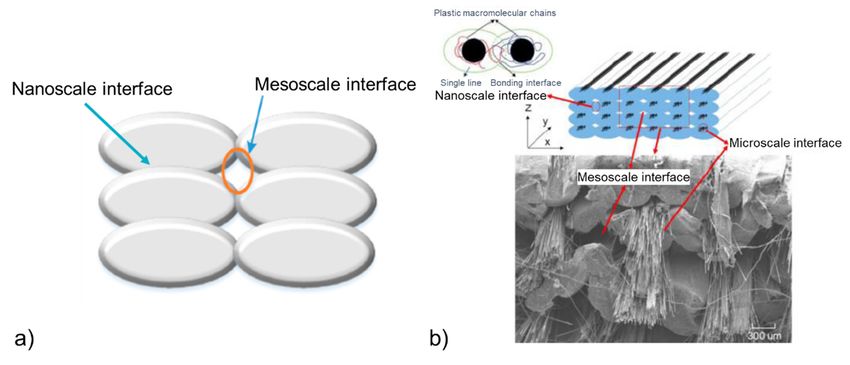
Polymers 2021, 13, 789                                                                                                                                4 of 28
Polymers 2021, 12, x FOR PEER REVIEW                                                                                                                      4 of 29

                                            Electron
                                        addition             microscopy
                                                       to pores     inducedtechniques
                                                                                by debonding   have     been fiber
                                                                                                   between      widely     usedand
                                                                                                                      bundles      to the
                                                                                                                                       characterize
                                                                                                                                            polymer matrix,in 2D
                                     mesoscale        and      microscale     interfaces    with    a  higher   resolution
                                        other defects were detected by µCT as fiber bundle disbonding and fiber damaging [15].compared       to  µCT     [19–21].
                                     However,         onlymicroscopy
                                               Electron        2D information        is provided
                                                                             techniques     have been andwidely
                                                                                                           to observe
                                                                                                                   used tosamples    prior in
                                                                                                                            characterize     to2Dany    mechan-
                                                                                                                                                    mesoscale
                                     ical
                                        andtesting,
                                              microscale careful    samplewith
                                                                interfaces     preparation     is required
                                                                                    a higher resolution         to avoidtothe
                                                                                                             compared        µCT induction     of defectsonly
                                                                                                                                   [19–21]. However,          due
                                     to2Dtheinformation
                                              preparationis (water-jet
                                                                   provided and       to observe
                                                                                 cutting   [20], ionsamples    prior
                                                                                                        abrasion      to any mechanical
                                                                                                                    methods                   testing, careful
                                                                                                                                [22]). In particular,       pores
                                     ofsample
                                         severalpreparation
                                                      microns resultingis required
                                                                                 fromtotheavoid    the induction
                                                                                             release     of gas were of identified
                                                                                                                         defects dueintoCFRTPC
                                                                                                                                            the preparation
                                                                                                                                                        printing
                                        (water-jet
                                     lines [11].        cutting    [20],  ion  abrasion    methods      [22]). In  particular,   pores   of several     microns
                                        resulting
                                            Concerning from the      release of
                                                                 nanoscale        gas were(weld
                                                                               interfaces     identified
                                                                                                      line),indirect
                                                                                                               CFRTPC      printing can
                                                                                                                     observation      linesbe[11].
                                                                                                                                                conducted by
                                     electron  Concerning
                                                    scanning nanoscale           interfaces (weld
                                                                   electron microscopy          [23] line),   direct observation
                                                                                                       and optical     microscopecan       be The
                                                                                                                                        [24].  conducted
                                                                                                                                                     weld line by
                                        electron      scanning       electron    microscopy      [23]   and   optical  microscope
                                     width in the case of acrylonitrile butadiene styrene (ABS) was measured to be in the range        [24].  The   weld     line
                                     ofwidth
                                         170–300  in the
                                                       µmcase      of acrylonitrile
                                                              (nominal     line width   butadiene
                                                                                          of around  styrene   (ABS)
                                                                                                         500 µm)        was measured
                                                                                                                   (Figure                to be inonthe
                                                                                                                              3c), depending               range
                                                                                                                                                        printing
                                        of 170–300 µm (nominal line width of around 500 µm) (Figure 3c), depending on printing
                                     speed and temperature [24]. Concerning weld line thickness or interpenetration depth, it
                                        speed and temperature [24]. Concerning weld line thickness or interpenetration depth,
                                     is dictated by the polymer interchain diffusion mechanisms at the interface. These mech-
                                        it is dictated by the polymer interchain diffusion mechanisms at the interface. These
                                     anisms have been investigated in detail based on models in the paper by [25]. One im-
                                        mechanisms have been investigated in detail based on models in the paper by [25]. One
                                     portant finding was that the interpenetration depth was around two times the radius of
                                        important finding was that the interpenetration depth was around two times the radius of
                                     gyration
                                        gyration    (R(R
                                                       g) of the polymer, meaning around 20 nm for PA [26]. However, as highlighted
                                                          g ) of the polymer, meaning around 20 nm for PA [26]. However, as highlighted
                                     ininFigure
                                           Figure    3c,3c,the
                                                             theintimate
                                                                  intimatecontact
                                                                              contactbetween
                                                                                         betweenthe  thetwo
                                                                                                          two polymer
                                                                                                               polymer faces      is not
                                                                                                                           faces is  not perfectly
                                                                                                                                           perfectly flatflatand
                                                                                                                                                              and
                                     besides,      the   nozzle      may   contain     impurities     that  interact   with   the
                                        besides, the nozzle may contain impurities that interact with the polymer at the molten    polymer      at the    molten
                                     state.
                                        state.It Itresults
                                                     resultsthatthat practically,
                                                                      practically, thetheweld
                                                                                           weld    line
                                                                                                line      thickness
                                                                                                      thickness        is probably
                                                                                                                  is probably    higherhigher
                                                                                                                                          than 2Rthan     2Rg, its
                                                                                                                                                    g , its exact
                                     exact   thickness
                                        thickness       being  being   not easily
                                                                 not easily          measurable.
                                                                               measurable.

         Figure 3. Visualization of interfaces in 3D printed materials: (a) mesoscale interfaces between printing lines in neat PLA
Figure 3. Visualization of interfaces in 3D printed materials: (a) mesoscale interfaces between printing lines in neat PLA by µCT
analysis by µCT
          [17], (b)analysis [17],interfaces
                    microscale    (b) microscale  interfaces
                                             resulting  from resulting   from fiber bundle-matrix
                                                              fiber bundle-matrix     debonding indebonding
                                                                                                     continuousincarbon
                                                                                                                      continuous   carbon fiber-
                                                                                                                             fiber-reinforced   PA ob-
served byreinforced
            µCT [18]PA(copyright
                         observed by         [18] (copyright
                                        µCT with
                                     (2020),       permission(2020),
                                                                 fromwith   permission
                                                                       Elsevier),        from
                                                                                   and (c)    Elsevier),interfaces
                                                                                            nanoscale     and (c) nanoscale   interfaces in neat
                                                                                                                     in neat acrylonitrile  butadiene
         acrylonitrile
styrene (ABS)          butadiene
                 observed          styrene
                            by optical     (ABS) observed
                                         microscopy    from by
                                                             thinoptical microscopy
                                                                    sample            from thin the
                                                                             slices, including  sample   slices, including
                                                                                                    principle              the principle
                                                                                                                 of this interface        of this[24,27]
                                                                                                                                    formation
         interface
(copyright  (2017)formation
                    and (2019),[24,27]
                                  with (copyright
                                        permission(2017)
                                                     from and   (2019), with permission from Elsevier).
                                                           Elsevier).

                                     2.2. Mechanical Properties
                                           Tensile testing on the laminate of unidirectional plies (UD) (0° or 90°) has been widely
                                     considered to evaluate the tensile modulus and the tensile strength of 3D printed compo-
                                     sites. In general, tensile testing conducted in the case of 0° UD composites (along printing
Fused Filament Fabrication of Polymers and Continuous Fiber-Reinforced Polymer Composites: Advances in Structure Optimization and Health ...
Polymers 2021, 13, 789                                                                                           5 of 28

                         2.2. Mechanical Properties
                                Tensile testing on the laminate of unidirectional plies (UD) (0◦ or 90◦ ) has been
                         widely considered to evaluate the tensile modulus and the tensile strength of 3D printed
                         composites. In general, tensile testing conducted in the case of 0◦ UD composites (along
                         printing line/fiber direction) exhibited an elongation at the break in the range of 1–5% of
                         the strain (Figure 4a), whereas the tensile modulus and strength varied significantly from
                         one study to another study, depending on the composite design (tensile modulus in the
                         range of 2.4–61 GPa, tensile strength in the range of 27–700 MPa) [28–30]. Compared
                         to CFRTPCs fabricated by conventional methods, and for a similar fraction of fibers, 3D
                         printed CFRTPCs exhibited a similar or even higher tensile strength, but an elastic modulus
                         four to five times lower, as shown in the case of carbon fiber-reinforced PA [29]. This lower
                         elastic modulus can be attributed to mesoscale and microscale interfaces exhibiting pores,
                         and to the presence of nanoscale interfaces (weld lines). In the case of 3D printed neat TP
                         (PLA), the highest tensile modulus and strength were obtained for the material exhibiting
                         the lowest porosity fraction [17]. Accordingly, the presence of pores is currently being
                         introduced in the model predicting the elastic modulus of 3D printed TP [17]. The tensile
                         properties for 90◦ UD composites are obviously lower than for 0◦ UD composites, the three
                         different kinds of interfaces being highly solicited [28,30]. One limitation of such tensile
                         testing is that it provides the overall macroscopic mechanical signature of the printed
                         structure, including the deformation signature of the matrix to a certain extent, and the
                         failure signature of all the interfaces, as represented in Figure 4a. To improve the material,
                         it is important to reveal the influence of its weakest points on mechanical properties and/or
                         to reveal the intrinsic behavior of the TP matrix.
                                Accordingly, interlaminar testing was developed to specifically stress the weakest
                         points of the structure being the three interfaces (Figure 1). To this end, short beam shear
                         (SBS) testing was applied to 3D printed materials to measure the maximum amount of
                         shear that can withstand the laminate between layers before failure. In principle, for
                         carbon fiber-reinforced TP, SBS generated a crushing of the carbon fibers at the sample
                         side in compression. This phenomenon induced a crack that propagated to the opposite
                         side of the sample that was in tension, soliciting mesoscale and nanoscale interfaces of
                         the printed lines [29]. SBS testing enables the interlaminar shear strength (ILSS) to be
                         extracted, as represented in Figure 4b [19,31]. In the case of neat PA printed in 3D, ILSS
                         slightly decreased (from 10.2 MPa to 9.3 MPa) as the printed line thickness increased
                         (from 0.1 mm to 0.2 mm) due to a higher porosity content [31]. In the case of 3D printed
                         PA composites, ILSS decreased in this material order: PA/carbon fibers (22.2 MPa for
                         27 vol% of fibers) > PA/glass fibers > PA/kevlar fibers. This finding was related to the
                         fibers-matrix wettability that was the highest for carbon fibers and the worst in the case of
                         Kevlar, showing the influence of microscale interfaces [31].
                                Recently, interlaminar fracture under mode I loading was successfully applied to
                         CFRTPCs based on double cantilever beam (DCB) testing [32]. For this testing, a pre-crack
                         is introduced in the 3D printed composite with an insert. This measurement provides
                         the energy dissipated by the formation of new fracture surfaces from the initial crack
                         propagation. However, the printing of the samples appears very complex. As for nanoscale
                         interfaces, specific methods have been developed to relate printing conditions (temperature
                         and speed) and polymer viscosity to the nanoscale interfacial adhesion in neat 3D printed
                         TP [24,27,33]. This interfacial adhesion influenced by the interpenetration depth [25] was
                         measured by “trouser tear” Mode III fracture testing (Figure 4c) [24] and by the ratio
                         between the tensile strength of the printed interface to bulk tensile strength based on chain
                         reptation theory [27]. It was demonstrated that nanoscale interfacial adhesion increased
                         with printing temperature and with decreasing polymer viscosity by adding a plasticizer,
                         whereas printing speed had a limited influence on this interfacial adhesion (Figure 4c).
Fused Filament Fabrication of Polymers and Continuous Fiber-Reinforced Polymer Composites: Advances in Structure Optimization and Health ...
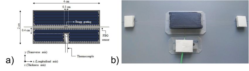
Polymers 2021, 13, 789                                                                                                                           6 of 28
Polymers 2021, 12, x FOR PEER REVIEW                                                                                                                 6 of 29

Figure 4.Figure
           Main 4.   Main mechanical
                  mechanical    testing testing   of 3D printed
                                         of 3D printed    neat TPsneat
                                                                     andTPsCFRTPCs:
                                                                            and CFRTPCs:     (a) tensile
                                                                                      (a) tensile        testing
                                                                                                   testing  of 0° of
                                                                                                                   UD 0◦ laminate
                                                                                                                          UD laminate     composite
                                                                                                                                     composite    (PA with
carbon or(PA  with
            glass   carbon
                  fibers)    or(copyright
                          [29]  glass fibers) [29] (copyright
                                            (2018),             (2018), with
                                                     with permission     frompermission   from
                                                                              Elsevier), (b)     Elsevier),
                                                                                             short           (b) short
                                                                                                     beam shear    (SBS)beam    shear
                                                                                                                           testing  to (SBS)
                                                                                                                                       measuretesting
                                                                                                                                                  the inter-
laminar to
         shear  strength
             measure   the(ILSS)   of glassshear
                            interlaminar    and Kevlar
                                                  strengthfiber-reinforced
                                                             (ILSS) of glassPA,
                                                                              and[31] (copyright
                                                                                   Kevlar           (2018), with
                                                                                           fiber-reinforced    PA,permission      from(2018),
                                                                                                                    [31] (copyright      Elsevier),
                                                                                                                                                 withand (c)
weldingpermission
          line adhesion
                      from measured
                             Elsevier),by “trouser
                                        and          tear”line
                                             (c) welding    Mode   III fracture
                                                               adhesion         testing
                                                                           measured     in the case
                                                                                     by “trouser      of Mode
                                                                                                  tear”  neat acrylonitrile    butadiene
                                                                                                                III fracture testing   in thestyrene
                                                                                                                                               case of(ABS)
[24,33] (copyright   (2017), with
         neat acrylonitrile         permission
                              butadiene  styrenefrom
                                                   (ABS)the Royal(copyright
                                                          [24,33]   Society of(2017),
                                                                                Chemistry
                                                                                      with and    Elsevier).
                                                                                            permission    from the Royal Society of Chemistry
         and Elsevier).
                                      2.3. Improving Interfacial Bonding
                                           Numerous methods are currently in development to increase neat TP and CFRTPC
                                      interfacial bonding, as detailed in a previous review [34]. The main approaches can be
Fused Filament Fabrication of Polymers and Continuous Fiber-Reinforced Polymer Composites: Advances in Structure Optimization and Health ...
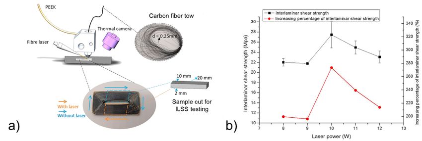
Polymers 2021, 13, 789                                                                                           7 of 28

                         2.3. Improving Interfacial Bonding
                              Numerous methods are currently in development to increase neat TP and CFRTPC
                         interfacial bonding, as detailed in a previous review [34]. The main approaches can be
                         classified into three categories: (1) adhesion engineering, (2) printing quality optimization,
                         and (3) material design optimization.

                         2.3.1. Adhesion Engineering
                               Adhesion engineering methods aim at improving the bonding at the continuous fiber-
                         matrix interface and between printed lines, thereby enhancing adhesion at the microscale
                         and mesoscale interfaces. Several approaches were considered, including the use of a
                         coupling technology between the carbon fibers (generally impregnated with epoxy) and the
                         TP matrix [19,21]. It was proven that an appropriate carbon fiber sizing has to be developed
                         when considering a TP as matrix [19]. When comparing unsized and sized carbon fiber,
                         the flexural strength of PA composite increased by 82% at a fiber volume fraction of 16%
                         (Figure 5a). The sizing consisted of removing the epoxy impregnation with acetone and
                         then dipping the unsized fiber in a water-based solution of PA. Last, the PA sizing was
                         melted through the printed nozzle to homogenize it. In addition, the effect of a plasma
                         pre-treatment of carbon fibers before their impregnation in a polyether-ether-ketone (PEEK)
                         TP matrix was investigated [35]. It was shown that not only was the interlayer bonding
                         improved but also the stability of the printing process. Another relevant method found in
                         the literature is the use of adhesion promoter, as polydopamine (PDA) that was successfully
                         used in the 3D printing process of PLA [36]. In particular, PLA pellets were coated with
                         PDA prior to extrusion, resulting in a 10% increase in tensile strength compared to untreated
                         PLA. Some structural analysis by X-ray photoelectron spectroscopy and Fourier-transform
                         infrared spectroscopy proved a covalent immobilization of PDA onto PLA. Note that
                         this methodology, inspired by mussel adhesive proteins [37], was previously used in the
                         case of epoxy reinforced with continuous carbon fibers manufactured by conventional
                         techniques. In this case, there was an increase of 20–25% of fracture toughness by DCB
                         testing and of ILSS compared to the untreated composite, due to the increased bonding
                         between epoxy and carbon fibers [38]. PDA was also successfully applied in TP reinforced
                         with carbon fiber based on a self-assembly approach to treat carbon fibers [39]. In the case
                         of neat 3D printed TP, epoxy adhesive was used to improve the flexural strength of the
                         material [40]. However, a specific process has been developed to have an effective influence
                         of the epoxy. ABS was printed with channels oriented perpendicular to the interlayer
                         direction, and the plasma surface was treated to increase wettability and infiltrated with
                         an epoxy/hardener mixture. The flexural strength was demonstrated to improve by 50%
                         with the plasma treatment and by 130% when combining plasma treatment and the epoxy
                         adhesive treatment. One limitation of this method is the long treatment time needed to
                         fully cure the epoxy resin.

                         2.3.2. Printing Quality Optimization
                              Then, many approaches were proposed to improve the quality of FFF printed parts.
                         They generally aimed at improving interlayer bonding through better management of both
                         mesoscale interfaces and nanoscale interfaces. For the latter, several strategies targeting
                         better polymer interchain diffusion at the interlayer level were considered. They are based
                         on optimizing printing parameters and applying various treatments, including treatments
                         of the filament and/or interlayer interface and post-treatments of the 3D printed material.
                              It was first shown that printing parameters should be optimized concerning mechan-
                         ical properties [19,23,27,33,41,42]. For example, the flexural strength of 3D printed PA6
                         composites had an optimal value concerning filament feeding rate (Figure 5a) [19], and the
                         tear energy increased with the nozzle temperature in the case of neat ABS (Figure 4c) [24].
                         Note that the flexural strength increased with the fraction of fiber, as represented in
                         Figure 5a for PA composites [19]. The critical role of polymer interchain diffusion for the
                         management of interlayer bonding is mentioned in several studies [27,42].
Fused Filament Fabrication of Polymers and Continuous Fiber-Reinforced Polymer Composites: Advances in Structure Optimization and Health ...
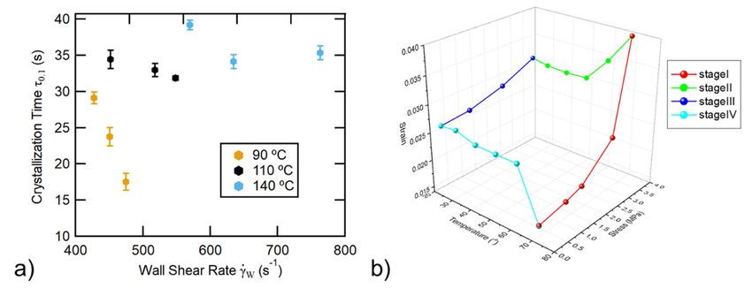
Polymers 2021, 13, 789                                                                                                                    8 of 28
2, x FOR PEER REVIEW                                                                                                                8 of 29

              Figure 5. (a) Effect of printing parameters, sizing, and fiber fraction on the mechanical strength of 3D printed PA com-
              positeFigure   5. (a) Effect
                     [19] (copyright       of printing
                                      (2018),          parameters,
                                              with permission       sizing, and
                                                              from Elsevier) and fiber fraction
                                                                                 (b) effect       on the mechanical
                                                                                            of annealing             strength
                                                                                                         on the mechanical     of of 3D
                                                                                                                           strength
                    3D  printed   PA  composite   [19] (copyright (2018), with  permission
              printed PLA [20] (copyright (2019), with permission from Elsevier).
                                                                                               from  Elsevier) and (b) effect of
                    annealing on the mechanical strength of 3D printed PLA [20] (copyright (2019), with permission
                    from Elsevier).            The printing process can be modified by introducing an in situ pre-heating of the
                                         base layer before the successive weld line is deposited. This thermal pre-treatment aims at
                    2.3.2. Printing Quality    Optimization
                                         improving     nanoscale interface bonding by promoting interchain diffusion. The treatment
                                         can be conducted with a laser [21,43], an infrared lamp [44], or forced hot air [45]. In the case
                          Then, many approaches          were proposed to improve the quality of FFF printed parts.
                                         of laser pre-heating, the optimal temperature was found to be between the glass transition
                    They generally aimed at improving interlayer bonding through better management of
                                         temperature and the degradation temperature of PEEK (Figure 6a). Under these conditions,
                    both mesoscale interfaces      and nanoscale
                                         ILSS increased    by a factor  interfaces.     For the
                                                                           of three (Figure        latter,
                                                                                                6b).        several strategies
                                                                                                     The coupling                    target- aiming at
                                                                                                                       of two approaches
                    ing better polymerimproving
                                           interchain     diffusion    at   the  interlayer     level   were    considered.
                                                       different interfaces was implemented by the same research team            They     arethrough the
                    based on optimizing       printing of
                                         development       parameters        and applying
                                                             a plasma pre-treatment                various
                                                                                              of carbon        treatments,
                                                                                                           fibers  (CF) beforeincluding
                                                                                                                                  impregnation of the
                    treatments of the filament and/or interlayer interface and post-treatments of the
                                         fibers by  PEEK    [35].  Then    CF  pre-impregnated        filament    was  printed    in      3D
                                                                                                                                      laser-assisted FFF
                    printed material. equipment to make samples for ILSS testing. It was reported that the implementation of
                                         both plasma
                          It was first shown             and laser
                                               that printing         treatmentsshould
                                                                  parameters        in the overall    printing process
                                                                                              be optimized                 provides
                                                                                                                  concerning     mechan-the best samples
                                         in terms of flexural properties and reduced porosity.
                    ical properties [19,23,27,33,41,42]. For example, the flexural strength of 3D printed PA6
                                               Advances in chemical modifications of filaments or interfaces to improve the quality of
                    composites had an optimal value concerning filament feeding rate (Figure 5a) [19], and
                                         printing are discussed in the literature. For instance, Ko et al. [27] investigated the addition
                    the tear energy increased
                                         of small with
                                                   amountsthe nozzle      temperature
                                                                of triphenyl     phosphate   in(TPP)
                                                                                                 the case    of neatinABS
                                                                                                        plasticizer            (Figure 4c) (PC)-ABS
                                                                                                                         a polycarbonate
                    [24]. Note that the blend
                                          flexural   strength
                                                filament.         increased
                                                             It was   reportedwith that the
                                                                                         thisfraction
                                                                                               additionof  offiber,  as represented
                                                                                                              plasticizer   improved the   in interfacial
                    Figure 5a for PA composites         [19].  The   critical   role   of polymer      interchain     diffusion
                                         bonding of printed parts through an improved degree of healing. In another study [46],      for  the
                    management of interlayer        bondingplasticizers
                                         benzene-derivate        is mentioned        in several
                                                                               obtained     from thestudies    [27,42].
                                                                                                        pyrolysis    of trisilanolphenyl polyhedral
                          The printing oligomeric
                                         process can  silsequioxane
                                                          be modified    (POSS)   were successfully
                                                                              by introducing         an inused   to improve
                                                                                                              situ  pre-heatingthe mesoscale
                                                                                                                                      of the interface
                                         bonding    of 3D  printed    PEEK.     In  addition,   a  method
                    base layer before the successive weld line is deposited. This thermal pre-treatment aims  based  on  atmospheric       pressure cold
                                         plasma   treatment     of the  polymer      filament   is  under
                    at improving nanoscale interface bonding by promoting interchain diffusion. The treat-  development       [47]. More    precisely, an
                                         atmospheric pressure dielectric barrier discharge (DBD) plasma torch has been imple-
                    ment can be conducted with a laser [21,43], an infrared lamp [44], or forced hot air [45]. In
                                         mented on a 3D printer. The objective of this technology is to modify the wettability of the
                    the case of laser pre-heating, the optimal temperature was found to be between the glass
                    transition temperature and the degradation temperature of PEEK (Figure 6a). Under these
                    conditions, ILSS increased by a factor of three (Figure 6b). The coupling of two approaches
                    aiming at improving different interfaces was implemented by the same research team
                    through the development of a plasma pre-treatment of carbon fibers (CF) before impreg-
Fused Filament Fabrication of Polymers and Continuous Fiber-Reinforced Polymer Composites: Advances in Structure Optimization and Health ...
Polymers 2021, 13, 789                                                                                                                     9 of 28

                                   base printed line to better deposit the welding line onto it, enhancing polymer adhesion
                                   by introducing new polar groups at the treated polymer surface. Some initial promising
                                   results were obtained on the influence of this plasma treatment on the interfacial adhesion,
                                   but a deeper knowledge on the influence on the treatment parameters (voltage, power, gas
                                   composition and flow rate, exposure time, etc.) on the efficiency of the plasma treatment is
                                   required. Another approach relies on the use of low-molecular-weight surface-segregating
                                   additives in the polymer filament that can diffuse and entangle in adjacent lines during
                                   the printing [48,49]. These linear additives can also contain a functional group providing
                                   a three-arm structure, reacting with UV irradiation that was applied in situ during the
                                   printing. This functionality led to a covalent bonding between adjacent additive molecules.
                                   An increase in the transverse maximum tensile stress of FFF printed PLA of 140% in the case
                                   of linear additive and of 200% in the case of the three-arm additive was noted compared to
                                   as-printed PLA. It was discussed that a balance has to be found between the covalent bond-
                                   ing of the additives and the mobility of the latter to diffuse across the mesoscale interface.
                                   In [50], neat PLA was blended with a radiation sensitizer prior to 3D printing. After FFF,
                                   specimens were irradiated with gamma rays (50 kGy, 60 ◦ C) and tested. The mechanical
                                   testing showed a 50% increase in tensile strength when applying strain perpendicular to
                                   the printed lines This finding was explained by the crosslinking reaction between printed
                                   lines, however, in this previous study, the stability of the irradiated specimens (presence of
                                   free radicals) was not studied.
Polymers 2021, 12, x FOR PEER REVIEW                                                                                      10 of 29
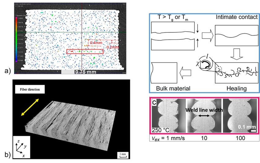
     Figure
      Figure6.6.Laser-assisted
                 Laser-assistedprinting
                                 printing process [21]: (a) diagram
                                                            diagramof  ofthe
                                                                          thepreparation
                                                                              preparationofofcontinuous
                                                                                               continuous  CF/PEEKcomposite
                                                                                                        CF/PEEK      composite  samples
                                                                                                                             samples for
     for ILSS
      ILSS     testing
            testing    and
                     and (b)(b) ILSS
                             ILSS    and
                                   and    increasing
                                       increasing    percentage
                                                   percentage   of of ILSS
                                                                   ILSS     with
                                                                         with    different
                                                                               different    laser
                                                                                         laser    powers
                                                                                               powers    (copyright
                                                                                                      (copyright    (2019)
                                                                                                                 (2019)    with
                                                                                                                        with    permis-
                                                                                                                             permission
     sion
      fromfrom   Elsevier).
            Elsevier).

                                  2.3.3. Material
                                          DifferentDesign     Optimization
                                                       kinds of  thermal post-treatments of the 3D printed material were investi-
                                   gated.    This  post-treatment
                                         Another approach based       can
                                                                        onbetheperformed     by a simple
                                                                                 material design            annealing
                                                                                                      optimization    canprocedure      [20,51],
                                                                                                                            be considered       toa
                                   combination       of  annealing   and  pressure     [52], annealing    in  the presence
                                  obtain printed parts with better mechanical properties. This approach involves the screen-  of   thermally     ex-
                                   pandable
                                  ing  of the rawmicrospheres     [53], microwaves
                                                     material properties                 [54], or
                                                                            to detect risks       ultrasonic
                                                                                                and            vibration
                                                                                                    the reduction    of the[55].
                                                                                                                            printedIn the  case of
                                                                                                                                        material
                                   microwaves post-treatment, a special carbon nanotube ink was developed to cover the
                                  anisotropy.
                                   TP filament     in theofprinter
                                         In the works               [54]. Thisthe
                                                            [57], screening     inktowpreg
                                                                                      is used and
                                                                                                as a the
                                                                                                     heating   source
                                                                                                         polymer       whenstructural
                                                                                                                    matrix     irradiated     with
                                                                                                                                            prop-
                                   microwaves      to  further  improve   the  polymer     interchain  diffusion   between
                                  erties prior to printing was proposed to potentially identify any risks that may be detri- the    printed   lines,
                                   providing
                                  mental         a 275%
                                            for the       increase
                                                     interfacial    in the fracture
                                                                 bonding.              strength
                                                                             Accordingly,      the(“trouser  tear”microstructure,
                                                                                                   composition,     Mode III fracture   andtesting)
                                                                                                                                              me-
                                   compared       to  the untreated    3D  printed     materials.    Moreover,    the  ability
                                  chanical properties of these two constituents were carefully analyzed. The main findings       of   this  design
                                   to locally
                                  can           induce heating
                                       be summarized               through
                                                           as follows:        this microwave-sensitive
                                                                        (1) Depending       on its nature thecoating
                                                                                                                polymer allows
                                                                                                                           matrix thecan
                                                                                                                                       annealing
                                                                                                                                          absorb
                                  up to 8% of water and needs to be dried before printing to avoid bubble and poreswhere
                                   treatment—as       low  as 60 s of microwave     treatment—to      be sped   up by  heating   the   part  [11];
                                   it is
                                  (2) thenecessary,
                                           polymer i.e.,   close
                                                       resin usedtofor
                                                                    theimpregnating
                                                                        interfilament interfaces.      Concerning
                                                                                          the fibers and             annealing,
                                                                                                           the TP polymer           in the case
                                                                                                                              composite       ma-of
                                   a  semi-crystalline    TP,  the optimal   temperature      is between   the  glass transition
                                  trix were often of different nature and microstructure, influencing interfacial bonding and        temperature
                                   and the cold crystallization temperature. Indeed, the formation of crystals may hinder the
                                  the modelling material inputs; and (3) the carbon towpreg may exhibit a heterogeneous
                                   interchain diffusion [20]. In the case of PLA, some cold-crystallization investigations by
                                  spatial distribution of its two constituents (carbon fibers and the impregnating ◦resin),
                                   X-ray diffraction (XRD) revealed that PLA started to crystallize quickly from 90 C, and
                                  drastically influencing the stress distribution and hence, the mechanical performance.
                                  Therefore, any identified risks should be addressed prior to printing.
                                         Last, advances in the 3D printing design of polymers [58] or polymer composites [59]
                                  were proposed based on the build direction. The first study disclosed the implementation
                                  of the so-called Z-pinning to reinforce the mechanical properties of printed parts in the Z
                                  (perpendicular to layers) direction. The second study was inspired by designs already de-
Fused Filament Fabrication of Polymers and Continuous Fiber-Reinforced Polymer Composites: Advances in Structure Optimization and Health ...
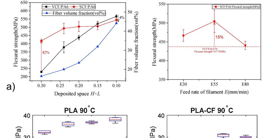
Polymers 2021, 13, 789                                                                                           10 of 28

                         that decreasing viscosity (by mechanical recycling) increased its crystallization rate [56].
                         This temperature was chosen as the post-treatment annealing temperature in the case of
                         3D printed neat and reinforced PLA with short fibers, for which tensile strength increased
                         by around 20% for neat PLA and by around 100% for the PLA composite compared to
                         untreated materials (Figure 5b).

                         2.3.3. Material Design Optimization
                               Another approach based on the material design optimization can be considered
                         to obtain printed parts with better mechanical properties. This approach involves the
                         screening of the raw material properties to detect risks and the reduction of the printed
                         material anisotropy.
                               In the works of [57], screening the towpreg and the polymer matrix structural proper-
                         ties prior to printing was proposed to potentially identify any risks that may be detrimental
                         for the interfacial bonding. Accordingly, the composition, microstructure, and mechanical
                         properties of these two constituents were carefully analyzed. The main findings can be
                         summarized as follows: (1) Depending on its nature the polymer matrix can absorb up to
                         8% of water and needs to be dried before printing to avoid bubble and pores [11]; (2) the
                         polymer resin used for impregnating the fibers and the TP polymer composite matrix
                         were often of different nature and microstructure, influencing interfacial bonding and the
                         modelling material inputs; and (3) the carbon towpreg may exhibit a heterogeneous spatial
                         distribution of its two constituents (carbon fibers and the impregnating resin), drastically
                         influencing the stress distribution and hence, the mechanical performance. Therefore, any
                         identified risks should be addressed prior to printing.
                               Last, advances in the 3D printing design of polymers [58] or polymer composites [59]
                         were proposed based on the build direction. The first study disclosed the implementation
                         of the so-called Z-pinning to reinforce the mechanical properties of printed parts in the
                         Z (perpendicular to layers) direction. The second study was inspired by designs already
                         developed for traditional composites in which reinforcement fibers are generally oriented
                         in the three directions of the composite parts. It consequently proposed printing CFRTPCs
                         along sinusoidal trajectories. The interest of this novel concept to reduce mechanical
                         anisotropy was demonstrated by modifying the printing trajectories on the XY plane (layer
                         axis). As an outlook, extending the concept in the Z (perpendicular to layer) direction
                         is proposed.

                         2.4. Molecular Behavior of the Matrix
                              Knowledge of TP crystallization kinetics may help to find the best printing conditions
                         for improving interchain diffusion at the nanoscale interface, and in general, may contribute
                         to understanding the long-term stability of the material. In the case of 3D printed TP, they
                         were studied in two pioneer studies [60,61]. In particular, a special method combining in-
                         frared thermography and Raman spectroscopy was developed to measure the temperature
                         and the crystallinity during the extrusion of polycaprolactone (PCL). Note that as high-
                         lighted in another work, the cooling rate during the deposition of the melted polymer onto
                         the previous layers at the substrate temperature is in the range of 20–50 ◦ C/s [62]. In [60],
                         measurements were taken at the surface of an extruded line of PCL and it was revealed
                         that crystallization is faster when decreasing the extrusion temperature and increasing the
                         nozzle wall shear rate (Figure 7a). It was explained that increasing the shear rate facilitated
                         flow-induced crystallization. However, as highlighted by the authors, a skin/core effect
                         of the extruded line was expected with skin more crystallized than the core due to higher
                         shear at the outer surface. This study highlighted the structural complexity of the extruded
                         line of TP. Obviously, this extrusion-induced anisotropic structure of the TP matrix is
                         expected to influence both crystallization kinetics and chain-orientation mechanisms upon
                         an applied mechanical strain.
                              Chain orientation mechanisms were analyzed by small- and wide-angle X-ray scatter-
                         ing (SAXS/WAXS), as commonly done for semi-crystalline TP processed by conventional
core due to higher shear at the outer surface. This study highlighted the structural com-
                                plexity of the extruded line of TP. Obviously, this extrusion-induced anisotropic structure
                                of the TP matrix is expected to influence both crystallization kinetics and chain-orientation
                                mechanisms upon an applied mechanical strain.
                                      Chain orientation mechanisms were analyzed by small- and wide-angle X-ray scat-
Polymers 2021, 13, 789                                                                                                                    11 of 28
                                tering (SAXS/WAXS), as commonly done for semi-crystalline TP processed by conven-
                                tional extrusion or compression molding [63–66]. SAXS and WAXS enable amorphous
                                chain   orientation,
                                  extrusion             crystalline
                                              or compression           plan orientation,
                                                                    molding    [63–66]. SAXS  crystalline
                                                                                                  and WAXS  phase    transformation,
                                                                                                                 enable   amorphous chain  crystal-
                                line lamellae   orientation,     and   strain-induced     cavitation   to be characterized
                                  orientation, crystalline plan orientation, crystalline phase transformation, crystalline lamel-upon    drawing,
                                and
                                  laepossibly   in situ
                                       orientation,   and and   in real time using
                                                             strain-induced            synchrotron
                                                                                cavitation             facilities. In upon
                                                                                              to be characterized      the case    of 3D printed
                                                                                                                               drawing,      and
                                  possibly
                                TP,          in situ and in
                                     chain orientation          real time using
                                                             mechanisms      weresynchrotron
                                                                                     investigated  facilities.  In the caseSAXS/WAXS
                                                                                                      by time-resolved          of 3D printedfor
                                  TP, chain orientationnanocomposite
                                PLA/hydroxyapatite           mechanisms were    uponinvestigated     by time-resolved
                                                                                       cyclic tensile/thermal              SAXS/WAXS
                                                                                                                    solicitations    [67]. Theforlat-
                                  PLA/hydroxyapatite          nanocomposite       upon   cyclic  tensile/thermal
                                ter induced orientation/relaxation of the amorphous chain characterized by the strain solicitations    [67]. The
                                  latter
                                level of induced    orientation/relaxation
                                         the amorphous                           of thethe
                                                               peak position. With       amorphous
                                                                                             increasing chain  characterized
                                                                                                          stress   level at 70    by the
                                                                                                                                 °C,      strain
                                                                                                                                      amorphous
                                  level of the amorphous        peak  position.  With   the increasing   stress level  at 70  ◦ C, amorphous
                                peak strain increased (decrease of the distance between amorphous chain [63], whereas
                                  peak strain increased (decrease of the distance between amorphous chain [63], whereas
                                (1) cooling from 70 °C        to 22 °C at the maximum stress level, (2) stress unloading at 22 °C,
                                  (1) cooling from 70 ◦ C to 22 ◦ C at the maximum stress level, (2) stress unloading at 22 ◦ C,
                                and (3) heating without stress up to 70 ◦°C led to a decrease in amorphous peak strain
                                  and (3) heating without stress up to 70 C led to a decrease in amorphous peak strain
                                (increase   in the distance between amorphous chain) (Figure 7b). These previous works
                                  (increase in the distance between amorphous chain) (Figure 7b). These previous works
                                proved
                                  proved theapplicability
                                          the  applicability of  of the
                                                                     theSAXS/WAXS
                                                                          SAXS/WAXSmethods methods  to to studying
                                                                                                       studying         molecular
                                                                                                                   molecular           orientation
                                                                                                                                 orientation    in
                                in3D
                                   3Dprinted
                                        printedTP,TP,
                                                    but did not reveal the full picture of molecular behavior (limited imposedim-
                                                        but   did  not   reveal  the  full  picture   of molecular      behavior     (limited
                                posed   stress/strain,
                                  stress/strain,         little
                                                  little or  no or  no information
                                                                 information           about crystalline
                                                                                about crystalline   phase, nophase,    no investigation
                                                                                                                 investigation                of the
                                                                                                                                   of the initial
                                initial chain-orientation
                                  chain-orientation             anisotropy).
                                                        anisotropy).

      Figure 7. Thermal and mechanical molecular behavior of 3D printed TP: (a) crystallization kinetics of PCL as a function of
  Figure 7. Thermal and mechanical molecular behavior of 3D printed TP: (a) crystallization kinetics of PCL as a function of
      nozzle wall shear rate and temperature [60] (copyright (2018), with permission from Elsevier), and (b) amorphous chain
  nozzle wall shear rate and temperature [60] (copyright (2018), with permission from Elsevier), and (b) amorphous chain
      orientation mechanisms of PLA nanocomposite upon cyclic stress and thermal solicitations (increase in strain = decrease in
  orientation mechanisms of PLA nanocomposite upon cyclic stress and                 thermal solicitations (increase in strain = decrease
      distance between chain, and inversely) (stage I: stress loading at 70 ◦ C, stage II: cooling down to 22 ◦ C at the maximum
  in distance between chain, and inversely) (stage          I: stress loading at 70 °C, stage II: cooling down to 22 °C at the maximum
      stress level, stage III: stress unloading at 22 ◦ C, and stage IV: heating up to 70 ◦ C without stress) [67] (copyright (2019), with
  stress level, stage III: stress unloading at 22 °C, and stage IV: heating up to 70 °C without stress) [67] (copyright (2019),
     permission
  with   permission from  Elsevier).
                       from   Elsevier).

                                  2.5.
                                2.5.   ResearchtotoBe
                                     Research       BeTackled
                                                       Tackled
                                       Mostofofthe
                                      Most      the previous
                                                    previous studies
                                                             studiesrelated
                                                                      relatedthe macroscopic
                                                                               the           thermomechanical
                                                                                   macroscopic                  properties
                                                                                                 thermomechanical          of
                                                                                                                      properties
                                  3D printed CFRTPCs with the material design and microstructure to tentatively improve
                                of 3D printed CFRTPCs with the material design and microstructure to tentatively im-
                                  interface bonding and reduce the corresponding defect formation, which is considered their
                                prove interface bonding and reduce the corresponding defect formation, which is consid-
                                  weakest point. Attention has been mainly focused on reducing porosities induced by the
                                  different interfaces and on increasing polymer interchain diffusion between printed lines.
                                  Based on recent works [12,16], with the current porosity fraction of CFRTPCs being in the
                                  range of 5–10 vol%, it is not yet acceptable for aerospace application, which requires less
                                  than 1 vol% of porosity, but is near the acceptable limit for other applications, including
                                  automotive, i.e., 5 vol% [68]. Some research activities to be tackled were identified to
                                  further stimulate the development of 3D printed CFRTPCs.
                                       A specific challenge for the development of FFF process and the performance of
                                  printed parts is related to temperature control of the printing line since it has a direct
                                  influence on TP crystallization behavior. More particularly, this temperature significantly
Polymers 2021, 13, 789                                                                                            12 of 28

                         influences the interface temperature between the current printing line and the previously
                         deposited layer and therefore controls the interchain diffusion phenomenon [25] that
                         governs the interlayer adhesion [42]. This is why the addition of in situ pre-heating devices
                         to plain FFF printers was reported by many authors (see Section 2.3). The ability of laser
                         systems to deliver a given heat quantity on a given surface is definitely an asset compared
                         to other kinds of devices and can explain the improved mechanical performance reported
                         by some studies for neat TPs [43] or CFRTPCs [21]. In addition, better thermal management
                         of the printing process in FFF can be obtained through a combination of thermal modelling
                         and an experimental approach and may contribute to the printing of specimens with
                         improved mechanical performance [69].
                               An important aspect of 3D printed CFRTPC development is the improvement of the
                         microscale interface between the continuous fibers and the TP matrix. The development of
                         appropriate sizing, dedicated surface treatment, or the impregnation of fibers in a dedicated
                         resin is expected to be further investigated shortly. The coupling technology between the
                         fibers and the TP matrix should address both the bonding efficiency and the deformability
                         needed for the printing, which appears very challenging.
                               Furthermore, the molecular aspects of the TP matrix in 3D printed CFRTPCs has been
                         considerably neglected. Indeed, the extrusion induces a heterogeneous orientation state of
                         the matrix within the printed line. The latter is expected to drastically influence molecular
                         behavior during the solidification (crystallization) and the deformation (orientation) of
                         the matrix.
                               The rapid cooling of the melted TP matrix against the previously deposited layer at
                         the substrate temperature (generally in the range of 60–120 ◦ C) engenders the isothermal
                         crystallization of the TP matrix, influencing nano-interface bonding and consequently the
                         mechanical properties of the material. In regions of high initial orientation, fast crystalliza-
                         tion is expected, and inversely. Isothermal crystallization kinetics of the TP matrix have
                         been rarely studied by a systematic investigation in the case of 3D printed materials.
                               When a strain is applied to a 3D printed CFRTP component, the polymer matrix is
                         solicited and may orient and transmit stress to the continuous fiber. In regions of high
                         initial orientation, further orientation induced by the imposed strain may be limited, and
                         inversely. To our best knowledge, strain-induced orientation mechanisms of the TP matrix
                         have not been investigated in detail.
                               Obviously, TP matrix crystallization kinetics and orientation mechanisms should be
                         further investigated. The challenge here relies on the initial structural heterogeneity of the
                         TP matrix engendered by 3D printing (significant shearing by the extrusion nozzle and the
                         presence of interfaces) that has to be taken into account.
                               Better thermal management of the printing line process, further improvement of the
                         fiber-TP matrix interface bonding and deformability, and further understanding of TP
                         molecular aspects are highly desirable to develop the next generation of ultralightweight,
                         mechanically durable, and smart FFF materials.

                         3. Structure Health Monitoring
                         3.1. Fiber Bragg Grating Sensors
                              Fiber Bragg grating (FBG)-based sensors have been used for the last three decades
                         in various applications because of their environmental stability, light weight, small di-
                         mensions, high sensitivity, multiplexing ability, and immunity to electromagnetic inter-
                         ference [70]. They hence appear suitable to be integrated into CFRTPC materials as strain
                         sensors. Nonetheless, this type of sensor integration into CFRTPCs is seldom reported, and
                         there is room for further investigation. Kousiatza et al. [71] reported the embedment of FBG
                         sensors in continuous carbon or glass fiber-reinforced Nylon composite specimens during
                         the FFF printing process. The carbon fiber-reinforced specimens were printed with three
                         different fiber orientations (±45◦ , 0◦ , and 90◦ ), whereas the glass fiber-reinforced specimen
                         was designed with fibers oriented only at ±45◦ . It is worthwhile to mention that the printed
                         specimens displayed the same length and width, but the glass fiber-reinforced composites
Polymers 2021, 13, 789                                                                                                        13 of 28

                                   were deposited with a higher number of layers. The bottom part of each specimen was
                                   printed until the system reaches the midplane, at which point the deposition process was
                                   paused to allow an optical fiber sensor and a K-type thermocouple to be manually embed-
                                   ded (Figure 8a). Thereafter, the printing process was resumed, and the temperature and
                                   residual strains were monitored until the end of the printing process, as shown in Figure 8b.
                                   Afterwards, measurements were further recorded after the 3D printed CFRTPC specimen
                                   was removed from the print bed. In addition, based on the recorded FBG wavelengths
                                   under thermal loads, the thermal expansion coefficients of each 3D printed CFRTP compos-
                                   ite were also calculated within the relevant ranges of temperature. The interface between
                                   the FBG sensor and the CFRTPC material was observed by digital microscopy. The mag-
                                   nitude of the residual strains of FFF-fabricated composite samples generated during the
                                   3D printing process was calculated. It was based on the peak wavelength values recorded
                                   by the embedded FBG sensors and was influenced by the fiber type and orientation, as
                                   revealed in Figure 9. These characteristics had similar effects on the temperature profiles
                                   generated by the process, as well as the measured coefficient of thermal expansion (CTE)
                                   values of the composite specimens. The greatest magnitude measured for post-fabrication
                                   compressive residual strain in a free-standing state, i.e., when the parts are fully detached
                                   from the print bed, was related to the specimens reinforced with carbon fibers oriented at
                                   90◦ with a value equal to 3100.2 microstrains (µε). Concerning the temperature variations
                                   during the sequential layer deposition recorded by the thermocouple, it was uniform in the
                                   case of 0◦ and 90◦ reinforcing fiber orientations and non-uniform when the reinforcement
                                   was oriented at ±45◦ . As might be expected, the fiber type had significant influence due
                                   to its thermal properties. In another work by the same authors [72], a similar approach
                                   was reported, but on neat TP printed samples instead of 3D printed CFRTPCs. More
                                   precisely, in situ monitoring of 3D printed neat TP acrylonitrile butadiene styrene (ABS)
                                   was performed by means of the integrated FBG sensors and thermocouples enclosed by
                                   different layers (Figure 10). Equally important, the dependence of the magnitude of the
                                   generated residual strains on the specimen’s position on the print bed was also investigated.
                                   The real-time compressive strain magnitudes obtained from the Bragg peak wavelength
                                   values at the bottom part of the specimen were smaller than the average ones in the upper
                                   part, as given in Figure 11. Changes were only detectable while the deposited first layers
                                   were fully solidified. The greatest magnitude measured for post-fabrication compressive
                                   residual strain in a free-standing state corresponded to the third layer while the specimen
                                   was
Polymers 2021, 12, x FOR PEER REVIEW    horizontally positioned on the print bed with longitudinally embedded FBGs14with    of 29a
                                   value equal to 7384 microstrains (µε). In that study, the temperature profiles during the 3D
                                   printing FBG
                                  Recently,  process  werewere
                                                  sensors   not only  derived used
                                                                 successfully from to
                                                                                   themonitor
                                                                                       thermocouples    but also
                                                                                               the residual      calculated
                                                                                                            stresses  duringfrom
                                                                                                                             the
                                   the  peak wavelength    values  of the FBG  sensors by neglecting  the solidification residual
                                  FFF process of a PLA matrix, enabling a better understanding of the resulting structural
                                   strains and
                                  properties    knowing the initial reference temperature.
                                              [74].

      Figure 8. (a) Schematic of the midplane of a 0◦ fiber reinforcement orientation of a 3D printed CFRTPC with the location of
     Figure 8. (a) Schematic of the midplane of a 0° fiber reinforcement orientation of a 3D printed CFRTPC with the location
      the FBG sensor and the thermocouple, and (b) picture of a 3D printed CFRTPC specimen containing an embedded FBG
     of the FBG sensor and the thermocouple, and (b) picture of a 3D printed CFRTPC specimen containing an embedded FBG
      sensorand
     sensor   anda athermocouple
                     thermocouple[71]
                                   [71](copyright
                                        (copyright(2019),
                                                   (2019),with
                                                           withpermission
                                                                permissionfrom
                                                                           fromElsevier).
                                                                                Elsevier).
You can also read