Guided Endodontics: Accuracy of Access Cavity Preparation and Discrimination of Angular and Linear Deviation On Canal Accessing Ability - An Ex ...
←
→
Page content transcription
If your browser does not render page correctly, please read the page content below
Guided Endodontics: Accuracy of Access Cavity
Preparation and Discrimination of Angular and
Linear Deviation On Canal Accessing Ability – An Ex
Vivo Study
Ying-Hui Su
Kaohsiung Medical University Hospital
Cheng-Hui Chen
Kaohsiung Medical University
Chia-Hua Lin
Kaohsiung Medical University Hospital
Hui-Na Lee
Kaohsiung Medical University Hospital
Ker-Kong Chen
Kaohsiung Medical University
Yen-Kun Lin
National Chung Cheng University
Fu-Hsiung Chuang ( d860203@kmu.edu.tw )
Kaohsiung Medical University
Research Article
Keywords: Guided endodontics, Cone beam computed tomography, 3D printed guide, Accuracy.
Posted Date: August 12th, 2021
DOI: https://doi.org/10.21203/rs.3.rs-787952/v1
License: This work is licensed under a Creative Commons Attribution 4.0 International License.
Read Full License
Version of Record: A version of this preprint was published at BMC Oral Health on November 23rd, 2021.
See the published version at https://doi.org/10.1186/s12903-021-01936-y.
Page 1/16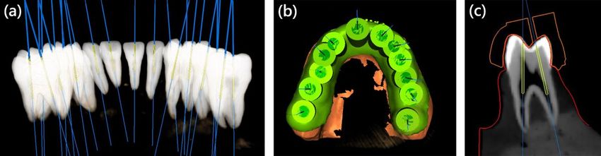
Abstract
Background
Guided endodontics technique has been introduced for years, but the accuracy in different types of teeth
has yet to be assessed. The aim of this study is to evaluate the accuracy of three dimensional (3D)-
printed endodontic guides for access cavity preparation in different types of teeth, and to evaluate the
predictive ability of angular and linear deviation on canal accessibility ex vivo.

Method
Eighty-four extracted human teeth were mounted into six jaw models and categorised into three groups:
anterior teeth (AT), premolar (P), and molar (M). Preoperative cone beam computed tomography (CBCT)
and surface scans were taken and matched using implant planning software. Virtual access cavity
planning was performed, and templates were produced using a 3D printer. After access cavities were
performed, the canal accessibility was recorded. Postoperative CBCT scans were superimposed in
software. Coronal and apical linear deviations and angular deviations were measured and evaluated with
nonparametric statistics. The receiver operating characteristic (ROC) curve was used to evaluate the
predictive ability of angular and linear deviation for canal accessibility in SPSS v20.

Results
A total of 117 guided access cavities were created and 23 of them were record as canal inaccessibility,
but all canals were accessible after canal negotiation. The average linear deviation for all groups was
0.13 ± 0.21 mm at coronal position, 0.46 ± 0.4 mm at apical position, and 2.8 ± 2.6° in angular deviation.
At the coronal position, the linear deviations of the AT and P groups were significantly lower than M group
deviation (P < 0.05), but no statistically significant difference between AT group and P group. The same
results were found in linear deviation at the apical position and in angular deviation. The area under the
ROC curve was 0.975 in angular deviation, 0.562 in linear deviation at the coronal position, and 0.786 at
the apical position. Statistical significance was noted in linear deviation at the apical position and in
angular deviation (P < 0.001).

Conclusions
In conclusion, this study demonstrated that the accuracy of access cavity preparation with 3D-printed
endodontic guides was acceptable. The linear and angular deviations in the M group were significantly
higher than those in the other groups, which might be caused by the interference of the opposite teeth.
Angular deviation best discriminated the canal access ability of guided access cavity preparation.

                                                 Page 2/16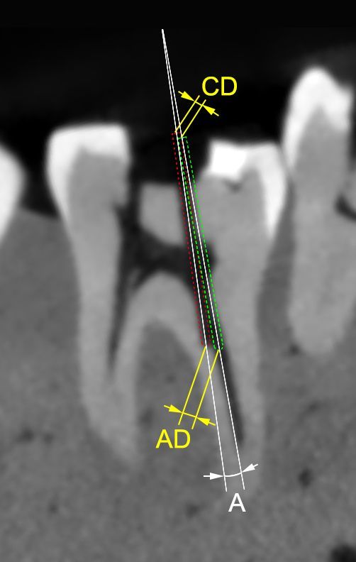
Background
The typical goal of endodontic treatment is to prevent or heal apical periodontitis [1]; however, endodontic
treatment can be challenging if pulp canal obliteration (PCO) has occurred [2]. PCO is characterised by
deposition of hard tissue in the root canal space. This is usually due to luxation injuries after dental
trauma [3] and can be caused by carious lesions [4], coronal restorations [5], and pulp capping [6].

The combination of dental operating microscopy (DOM) and an ultrasonic tip can be used to identify
obliterated canals [7]. Yet, even when DOM and an ultrasonic tip are used, treating teeth with PCO remains
time-consuming [8]. However, in endodontic treatment, cone beam computed tomography (CBCT) can
provide additional information via three-dimensional (3D) views [9]; thus, the use of CBCT has been
suggested for localising calcified canals [10].

Recently, researchers have introduced the concept of guided endodontics, in which 3D-printed guides are
used for preparing access cavities [11–13]. The idea of using 3D-printed guides in guided endodontics to
leverage 3D information from intraoral scans and CBCT was similar to guided implant surgery which was
reported earlier [14, 15].

The actual procedure of guided endodontics involves acquiring volumetric data through CBCT and
surface scan data from an intraoral scanner. Both data are superimposed in computer-aided design
(CAD) software for virtual access cavity planning and designing a template. Afterward, the template is
manufactured through 3D printing, and the cavity preparation is executed with drills [13, 15].

Several articles have reported on the use of the guided endodontics technique to locate anterior teeth with
PCO [12, 13, 16, 17]; this technique has also been used for posterior teeth with PCO [18–21]. These
studies demonstrated the clinical feasibility of this technique.

Furthermore, another ex vivo study reported that the mean distance between the axis of the virtual drill
path and the target point was 0.46 mm in 38 teeth [11]. Another study reported that the linear deviations
of guided endodontics were between 0.16 to 0.47 mm for different aspects at different bur positions in
maxillary incisors, laterals, canines, and premolars [22]. However, the linear deviations in mandibular
incisors and canines ranged from 0.12 to 0.34 mm [23]. Studies comparing the accuracy of access cavity
preparation among different types of teeth are lacking.

Therefore, the aims of this study were to evaluate the accuracy of access cavity preparation of 3D-printed
endodontic guides for different types of teeth and to evaluate the predictive ability of angular and linear
deviation on canal accessibility ex vivo.

Methods
In present study, all methods were carried out in accordance with Human Subjects Research Act and
informed consent was obtained according to Scope of Human Clinical Trials Exempted from Informed

                                                   Page 3/16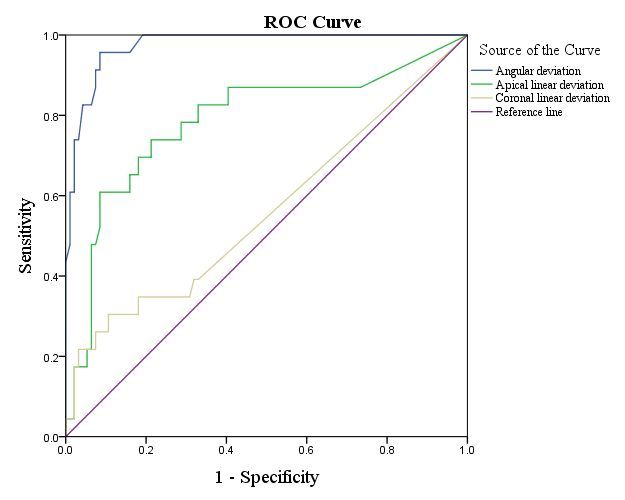
Consents of Subjects in Ministry of Health and Welfare, Taiwan (R.O.C.). The ethical approval was
obtained by Institutional Review Board of Kaohsiung Medical University Memorial Hospital (KMUHIRB-
E(II)-20190406). The study protocol conformed to the principles outlined in the German Ethics
Committee’s statement.

Eighty-four extracted permanent teeth were collected, including 36 anterior teeth, 24 premolars, and 24
molars. All teeth were extracted due to periodontal disease, but endodontically treated teeth and teeth
with extensive decay or restoration were excluded. All teeth were mounted in six stone models, including
three maxillary models and three mandible models, according to their anatomic position from central
incisor to second molar.

For all models, preoperative CBCT with a voxel size of 150 µm was performed (NewTom VGi evo, CEFLA,
Imola, Italy), and data were saved in Digital Imaging and Communication in Medicine (DICOM) format.
Furthermore, the models were scanned with an intraoral scanner (3Shape TRIOS, 3Shape, Copenhagen,
Denmark), and surface data were saved in the stereolithography (STL) file format. Both types of data
were superimposed in dental CAD software (Implant Planning, Inteware, Chiayi, Taiwan) for virtual access
cavity planning.

The endodontic access bur (Munce Discovery Bur #1/4, Hager & Meisinger GmbH, Neuss, Germany) was
used for virtual access cavity planning. This bur has a tip diameter of 0.5 mm, shank diameter of 1 mm,
and a working length of 16 mm. A virtual image of burs 0.5 mm in diameter was planned using the
software, and a virtual bur was placed 3–4 mm below the cementoenamel junction with the axial within
the range of the conservative endodontic access cavity (Fig. 1a). Of the 84 teeth, 36 virtual burs were
positioned in anterior teeth, 33 burs in premolars, and 48 burs in molars. In anterior teeth, all canals were
planned. In premolars and molars, canals with complexity were excluded. For example, mesiobuccal root
in upper molar with first and second mesiobuccal canal, C-shape root canal in premolar and molar were
excluded to prevent the misjudgement of canal accessibility.

After virtual planning, the templates were designed using software (Guide Designer, Inteware, Chiayi,
Taiwan; Fig. 1b), and all resin sleeves in templates were designed with a 1.09-mm inner diameter and a 3-
mm sleeve height (Fig. 1c). Twelve templates were created in STL file format and fabricated with a 3D
printer (Form 2, Material: FLGPGR04, Formlabs, Somerville, USA). After the support material of the
templates was removed, a fit checking material (Fit Checker, GC Corporation, Tokyo, Japan) was used for
all templates.

All models were mounted in dental simulation units (DSE Expert, KaVo Dental GmbH, Biberach, Germany)
with the opposite jaw model to simulate the clinical situation and operated by a single endodontic
specialist. Enamel within the area of the conservative access cavity was removed with a round diamond
bur until the dentin was exposed, and templates were then attached to the models. The bur was used with
a low-speed handpiece to penetrate through the sleeve of the template with a pecking motion until the bur
hit the mechanical stop of the resin sleeve. The bur was cleaned with gauze, irrigation with sodium
hypochlorite was performed every 2 mm during drilling, and the bur was replaced every 10 canals. After
                                                  Page 4/16
guided access cavity preparation was completed, each canal was checked with a size 10 K-file (Dentsply
Sirona, Charlotte, USA) to evaluate the canal accessibility. If the K-file could reach the root canal through
guided access cavity preparation without any resistance, the procedure was deemed a canal accessibility;
otherwise, it was deemed a canal inaccessibility. After canal accessibility was recorded, root canal
negotiation was performed with ultrasonic tips (CPR®, Obtura-Spartan Corp., Fenton, MO) and K-files
under a microscope (OPMI pico, Zeiss, Oberkochen, Germany) from the guided access cavity.
Postoperative CBCT of all models was performed. All data, including those of preoperative and
postoperative CBCT, oral scans, and virtual planning, were imported and superimposed (Fig. 2) in a 3D
slicer (available at http://www.slicer.org/). The angular and linear deviations were measured in a 3D view.
The angle between the virtual bur axis and the actual bur axis was defined as angular deviation. The
distance between the bases of the virtual bur and actual bur was defined as coronal deviation, and the
distance between the tips of the virtual bur and actual bur was defined as apical deviation, and the angle
between the axis of virtual bur and actual bur was defined as angle deviation (Fig. 3).
Teeth were categorised into three groups: anterior teeth (AT), premolar (P), and molar (M). Statistical
analysis was performed with SPSS v20 (IBM, New York, USA). Nonparametric statistics were used, and
the significance level was set at 5% (P < 0.05). Receiver operating characteristic (ROC) curves were used
to evaluate the predictive ability of angular and linear deviation for canal accessibility.
Results
A total of 117 guided access cavities were created in 84 teeth, and 23 of them were record as canal
inaccessibility. Of the 23, 2 were in the AT group, 3 were in the P group, and 18 were in the M group. After
minor canal negotiation with ultrasonic tips and K-files from the guided access cavity, all canals were
accessible through the guided access cavities, and no canal perforation was noted. The average linear
deviation for all groups was 0.13 ± 0.21 mm at the coronal position, 0.46 ± 0.4 mm at the apical position,
with an average angular deviation of 2.8 ± 2.6°. Table 1 details the linear and angular deviations.
Page 5/16Table 1
The mean value, standard deviation, minimum, and maximum of the deviation in all groups.
Group
Anterior Premolar Molar Total
Guided access cavity (n) 36 33 48 117
Coronal linear deviation (mm) Mean 0.09 0.07 0.22 0.13
Standard deviation 0.16 0.15 0.25 0.21
Minimum 0.0 0.0 0.0 0.0
Maximum 0.54 0.49 0.97 0.97
Apical linear deviation (mm) Mean 0.28 0.40 0.64 0.46
Standard deviation 0.24 0.35 0.46 0.40
Minimum 0.0 0.0 0.0 0.0
Maximum 0.78 1.26 1.60 1.60
Angular deviation (°) Mean 1.73 2.23 4.00 2.80
Standard deviation 1.97 1.97 2.86 2.57
Minimum 0.0 0.0 0.0 0.0
Maximum 5.90 6.50 11.60 11.60
The coronal linear deviations for the AT and P groups were statistically significantly lower than the
deviation for the M group (P < 0.05), but no difference between the AT and P groups was measured (P =
1.00; Fig. 4a). The apical linear deviations for the AT and P groups were statistically significantly lower
than the deviation for the M group (P < 0.05), but no difference was measured between the AT and P
groups (P = 0.6; Fig. 4b). Additionally, angular deviations for the AT and P groups were also statistically
significantly lower than those for the M group (P < 0.05), but no difference was measured between the AT
and P groups (P = 1.00; Fig. 4c).
To evaluate the predictive ability of different deviations for canal accessibility, the outcomes were
illustrated with ROC curves (Fig. 5). The area under the ROC curve was 0.562 in linear deviation for the
coronal position (P = 0.36), 0.786 for the apical position (P < 0.001), and 0.975 for angular deviation (P <
0.001). Statistical significance was noted in the linear deviation of the apical position and for angular
deviation.
Discussion
Page 6/16The results of this ex vivo study demonstrated that the accuracy of access cavity preparation with 3D-
printed endodontic guides was acceptable, but the accuracy for the M group still demonstrated room for
improvement. Additionally, the angular deviation can be considered an outstanding discriminator of canal
accessibility.
Relatively early clinical research that applied the guided endodontics technique was published in 2015;
however, this article reported a 3D printing model instead of a 3D-printed template to custom make the
jigs required for guidance [24]. Subsequently, many articles reported on the guided endodontics technique
in AT [12, 16, 25, 26] and mainly focused on PCO. Studies using the same technique in posterior teeth
appeared later in 2019, but the total number of relevant articles remains relatively small [20, 21, 27].
Although the literature had indicated that the guided endodontics technique was clinically feasible for
both anterior and posterior teeth, no research had compared the accuracy of access cavity preparation
between different types of teeth.
Some ex vivo studies, however, had described the accuracy of guided access cavities. One study, which
used a 1.2-mm diameter drill, reported that the mean distance between the axis of the virtual drill path
and the target point was 0.46 mm in 38 teeth [11]. Although the calculation method was slightly different
than that herein because the study used two-dimensional measurement in a horizontal view, the data on
the total average apical linear deviation (0.46 mm) were similar to those in the present study. Another ex
vivo study, which mainly using maxillary AT with a 1.5-mm drill, reported that the mean apical deviation
ranged from 0.17 to 0.47 mm depending on the aspect (mesial/distal, buccal/palatal, apical/coronal
aspect), and the study also reported a 1.81° mean angle deviation [22]. The mean apical linear deviation
of AT was also similar to that of the present study (0.28 mm). However, the mean angle deviation was
slightly smaller in the present study (1.73°). The same research group published another article mainly
focused on mandibular AT using a 0.85-mm-diameter drill. The mean apical linear deviation was 0.12 to
0.34 mm in different aspects, and the mean angle deviation was 1.59°—both slightly smaller than those
of the present study [23]. Generally speaking, the outcomes of the present study do not differ
substantially from those of previous studies.
The present study is the first to compare the deviations between anterior, premolar, and molar teeth. All
the coronal, apical, linear, and angle deviations were significantly higher in the M group then in the other
two groups. The main possible reasons are as follows: all models were mounted in dental simulation
units to simulate the clinical situation; therefore, it might be more difficult to align the bur with the guide
sleeve in the molar area because of the lower interocclusal distance in molar area. When positioning the
contra angle handpiece in molar area, the head of the handpiece might be interfered by the opposite
teeth. This situation caused the entry point of the bur was deviated in the coronal position. As the bur
continues to go down, the deviation in coronal position caused more displacement until the bur reached
the apical position. Consequently, the apical linear deviation and angular deviation were affected. In
clinical situation, anterior teeth and premolar are easier to perform guided endodontics technique
because the interocclusal distance are greater than molar area. Furthermore, there are several clinical
limitations for executing successfully guided endodontics in molars: e.g., limited mouth opening, length
Page 7/16of the drill, thickness of template. In present study, the length of the bur plus the length of the handpiece
head was 28 mm and the thickness of template was 3mm, therefore, the operation was more likely to be
interfered by the opposite teeth in anterior and premolar area than in molar area.
For implant-guided surgery, the concept of intrinsic error of the surgical template was defined as the
mechanical error caused by the bur-cylinder gap, which can potentially affect the accuracy of the surgical
template [28]. Additionally, the researcher proposed that if the template sleeve length is 4 mm and the gap
between the drill and the sleeve is 0.2 mm, the intrinsic error can be calculated to be 2.86° using the arc-
tangent function. If the length of the sleeve is 5 mm and the gap between the drill and the sleeve is 0.2
mm, the intrinsic error is 2.29°. This means that the longer the sleeve length is, the smaller the intrinsic
error will be. In the present study, the sleeve length was 3 mm, and the gap between the drill and the
sleeve was 0.09 mm; therefore, the intrinsic error was 1.71°. To increase the accuracy of guided access
cavity preparation, the intrinsic error should be lowered by extending the sleeve or reducing the gap
between the drill and the sleeve, which was also demonstrated in another study [29]. It might be useful to
transfer the drill path into the access cavity to extending the sleeve, which was performed with light-cure
composite resin in a case report[20].
ROC curves are usually used to evaluate diagnostic test performance [30], but they can also be used to
predict clinical success, such as when applied for evaluating the ability to predict treatment success of
percutaneous nephrolithotomy according to different scores [31] or for predicting successful weaning
from mechanical ventilation according to different factors [32]. In the present study, the ROC curve was
used to predict the success of canal accessibility which defined as reaching the canal through guided
access cavity preparation. The areas under the ROC curve were 0.562 in coronal linear deviation, 0.786 in
apical linear deviation, and 0.975 in angular deviation. Therefore, angular deviation, followed by apical
linear deviation, best discriminated canal accessibility.
Finally, this study had two limitations. First, this test was not performed on PCO teeth, meaning that the
impact of related technologies on PCO teeth in different types of teeth remains unknown. Second, the M
group deviations were relatively high, and this may compromise the treatment outcome of guided access
cavities in molars. Advanced research is warranted to study the relatively high error in the molar area,
such as changing the sleeve design, extending the sleeve into access cavity, or using the extened metal
sleeve.
Conclusions
In conclusion, this study demonstrated that the accuracy of access cavity preparation with 3D-printed
endodontic guides was acceptable. The linear and angular deviations in the M group were significantly
higher than those in the other groups, which might be caused by the interference of the opposite teeth.
Angular deviation best discriminated the canal access ability of guided access cavity preparation.
Abbreviations
Page 8/163D
three dimensional; AT:anterior teeth; P:premolar; M:molar; CBCT:cone beam computed tomography;
ROC:receiver operating characteristic; PCO:pulp canal obliteration; CAD:computer-aided design;
DICOM:Digital Imaging and Communication in Medicine; STL:stereolithography
Declarations
Ethics approval and consent to participate
Ethical approval was obtained by Institutional Review Board of Kaohsiung Medical University Memorial
Hospital (KMUHIRB-E(II)-20190406).
Consent for publication
Not applicable.
Availability of data and materials
The datasets used and analysed during the current study are available from the corresponding author on
reasonable request.
Competing interests
The authors declare that they have no competing interests.
Funding
This study was supported by a grant from Kaohsiung Medical University Hospital (KMUH109-9M59).
Authors’ contributions
YHS designed the study, wrote the paper, carried out operation. CHC, HNL, KKC, FHC helped to revise the
paper. CHL helped to organize data. YKL helped with the CAD software. All authors have read and
approved the manuscript.
Acknowledgements:
Authors would like to thank Cheng-Hui Chen, Chia-Hua Lin, Hui-Na Lee, Ker-Kong Chen, Yen-Kun Lin, Fu-
Hsiung Chuang their assistance in this study. This manuscript was edited by Wallace Academic Editing.
Authors' information
1Division of Endodontics and Operative Dentistry, Dental Department, Kaohsiung Medical University
Hospital, Kaohsiung, 80708, Taiwan
2Dental Department, Kaohsiung Municipal Cijin Hospital, Kaohsiung, 805, Taiwan
Page 9/163School of Dentistry, College of Dental Medicine, Kaohsiung Medical University, Kaohsiung, 80708,
Taiwan
4Research Center for Precision Molding, National Chung Cheng University, Chiayi, 62102, Taiwan
References
1. Holcomb JB, Gregory WB. Calcific metamorphosis of the pulp: its incidence and treatment. Oral
Surgery, Oral Medicine, Oral Pathology 1967, 24(6):825–30. https://doi.org/10.1016/0030-
4220(67)90521-x
2. McCabe P, Dummer PMH. Pulp canal obliteration: an endodontic diagnosis and treatment challenge.
International Endodontic Journal 2012, 45(2):177–97. https://doi.org/10.1111/j.1365-
2591.2011.01963.x
3. Andreasen FM, Zhjie Y, Thomsen BL, Andersen PK. Occurrence of pulp canal obliteration after
luxation injuries in the permanent dentition. Dental Traumatology 1987, 3(3):103–15.
https://doi.org/10.1111/j.1600-9657.1987.tb00611.x
4. Sayegh F, Reed A. Calcification in the dental pulp. Oral Surgery, Oral Medicine, Oral Pathology 1968,
25(6):873–82. https://doi.org/10.1016/0030-4220(68)90165-5
5. Fleig S, Attin T, Jungbluth H. Narrowing of the radicular pulp space in coronally restored teeth.
Clinical Oral Investigations 2017, 21(4):1251–7. https://doi.org/10.1007/s00784-016-1899-8
6. Agamy HA, Bakry NS, Mounir MM, Avery DR. Comparison of mineral trioxide aggregate and
formocresol as pulp-capping agents in pulpotomized primary teeth. Pediatric Dentistry 2004,
26(4):302–9. https://doi.org/10.1038/sj.bdj.2008.319
7. Toubes KMS, Oliveira PAD, Machado SN, Pelosi V, Nunes E, Silveira FF. Clinical approach to pulp
canal obliteration: a case series. Iranian Endodontic Journal 2017, 12(4):527–33.
https://doi.org/10.22037/iej.v12i4.18006
8. Kiefner P, Connert T, ElAyouti A, Weiger R. Treatment of calcified root canals in elderly people: a
clinical study about the accessibility, the time needed and the outcome with a three-year follow‐up.
Gerodontology 2017, 34(2):164–70. https://doi.org/10.1111/ger.12238
9. Patel S, Kanagasingam S, Mannocci F. Cone beam computed tomography (CBCT) in endodontics.
Dental Update 2010, 37(6):373–9. https://doi.org/10.12968/denu.2010.37.6.373
10. Fayad MI, Nair M, Levin MD, Benavides E, Rubinstein RA, Barghan S et al. AAE and AAOMR joint
position statement: use of cone beam computed tomography in endodontics 2015 update. Oral
Surgery, Oral Medicine, Oral Pathology and Oral Radiology 2015, 120(4):508–12.
https://doi.org/10.1016/j.oooo.2015.07.033
11. Buchgreitz J, Buchgreitz M, Mortensen D, Bjorndal L. Guided access cavity preparation using cone-
beam computed tomography and optical surface scans - an ex vivo study. International Endodontic
Journal 2016, 49(8):790–5. https://doi.org/10.1111/iej.12516
Page 10/1612. Krastl G, Zehnder MS, Connert T, Weiger R, Kuhl S. Guided endodontics: a novel treatment approach
for teeth with pulp canal calcification and apical pathology. Dental Traumatology 2016, 32(3):240–6.
https://doi.org/10.1111/edt.12235
13. Meer WJ, Vissink A, Ng YL, Gulabivala K. 3D computer aided treatment planning in endodontics.
Journal of Dentistry 2016, 45:67–72. https://doi.org/10.1016/j.jdent.2015.11.007
14. Flügge TV, Nelson K, Schmelzeisen R, Metzger MC. Three-dimensional plotting and printing of an
implant drilling guide: simplifying guided implant surgery. Journal of Oral and Maxillofacial Surgery
2013, 71(8):1340–6. https://doi.org/10.1016/j.joms.2013.04.010
15. Dawood A, Marti BM, Sauret-Jackson V, Darwood A. 3D printing in dentistry. British Dental Journal
2015, 219(11):521–9. https://doi.org/10.1038/sj.bdj.2015.914
16. Fonseca TWL, Diniz VAC, Carvalho MV, Feitosa HLC, Ribeiro SAP. Guided endodontic access of
calcified anterior teeth. Journal of Endodontics 2018, 44(7):1195–9.
https://doi.org/10.1016/j.joen.2018.04.014
17. Lara-Mendes STO, Barbosa CFM, Machado VC, Santa-Rosa CC. A new approach for minimally
invasive access to severely calcified anterior teeth using the guided endodontics technique. Journal
of Endodontics 2018, 44(10):1578–82. https://doi.org/10.1016/j.joen.2018.07.006
18. Lara-Mendes STO, Barbosa CFM, Santa-Rosa CC, Machado VC. Guided endodontic access in
maxillary molars using cone-beam computed tomography and computer-aided design/computer-
aided manufacturing system: a case report. Journal of Endodontics 2018, 44(5):875–9.
https://doi.org/10.1016/j.joen.2018.02.009
19. Shi X, Zhao S, Wang W, Jiang Q, Yang X. Novel navigation technique for the endodontic treatment of
a molar with pulp canal calcification and apical pathology. Australian Endodontic Journal 2018,
44(1):66–70. https://doi.org/10.1111/aej.12207
20. Buchgreitz J, Buchgreitz M, Bjørndal L. Guided endodontics modified for treating molars by using an
intracoronal guide technique. Journal of Endodontics 2019, 45(6):818–23.
https://doi.org/10.1016/j.joen.2019.03.010
21. Maia LM, Carvalho MV, Silva NRFA, Júnior MB, Silveira RR, Júnior GM et al. Case reports in maxillary
posterior teeth by guided endodontic access. Journal of Endodontics 2019, 45(2):214–8.
https://doi.org/10.1016/j.joen.2018.11.008
22. Zehnder MS, Connert T, Weiger R, Krastl G, Kuhl S. Guided endodontics: accuracy of a novel method
for guided access cavity preparation and root canal location. International Endodontic Journal 2016,
49(10):966–72. https://doi.org/10.1111/iej.12544
23. Connert T, Zehnder MS, Weiger R, Kuhl S, Krastl G. Microguided endodontics: accuracy of a
miniaturized technique for apically extended access cavity preparation in anterior teeth. Journal of
Endodontics 2017, 43(5):787–90. https://doi.org/10.1016/j.joen.2016.12.016
24. Byun C, Kim C, Cho S, Baek SH, Kim G, Kim SG et al. Endodontic treatment of an anomalous anterior
tooth with the aid of a 3-dimensional printed physical tooth model. Journal of Endodontics 2015,
41(6):961–5. https://doi.org/10.1016/j.joen.2015.01.016
Page 11/1625. Ishak G, Habib M, Tohme H, Patel S, Bordone A, Perez C et al. Guided endodontic treatment of
calcified lower incisors: a case report. Dentistry Journal 2020, 8(3):74.
https://doi.org/10.3390/dj8030074
26. Hegde SG, Tawani G, Warhadpande M, Raut A, Dakshindas D, Wankhade S. Guided endodontic
therapy: management of pulp canal obliteration in the maxillary central incisor. Journal of
Conservative Dentistry 2019, 22(6):607. https://doi.org/10.4103/jcd.jcd_21_20
27. Maia LM, Toubes KM, Júnior GM, Tonelli SQ, de Carvalho Machado V, Silveira FF et al. Guided
endodontics in nonsurgical retreatment of a mandibular first molar: a new approach and case report.
Iranian Endodontic Journal 2020, 15(2):111–6. https://doi.org/10.1016/j.joen.2013.12.013
28. Cassetta M, Mambro A, Giansanti M, Stefanelli L, Cavallini C. The intrinsic error of a
stereolithographic surgical template in implant guided surgery. International Journal of Oral and
Maxillofacial Surgery 2013, 42(2):264–75. https://doi.org/10.1016/j.ijom.2012.06.010
29. Choi M, Romberg E, Driscoll CF. Effects of varied dimensions of surgical guides on implant
angulations. The Journal of Prosthetic Dentistry 2004, 92(5):463–9.
https://doi.org/10.1016/j.prosdent.2004.08.010
30. Fan J, Upadhye S, Worster A. Understanding receiver operating characteristic (ROC) curves. Canadian
Journal of Emergency Medicine 2006, 8(1):19–20. https://doi.org/10.1017/s1481803500013336
31. Smith A, Averch TD, Shahrour K, Opondo D, Daels FP, Labate G et al. A nephrolithometric nomogram
to predict treatment success of percutaneous nephrolithotomy. The Journal of Urology 2013,
190(1):149–56. https://doi.org/10.1016/j.juro.2013.01.047
32. Tenza-Lozano E, Llamas-Alvarez A, Jaimez-Navarro E, Fernández-Sánchez J. Lung and diaphragm
ultrasound as predictors of success in weaning from mechanical ventilation. Critical Ultrasound
Journal 2018, 10(1):1–9. https://doi.org/10.1186/s13089-018-0094-3
Figures
Figure 1
Virtual planning in implant software: (a) Virtual access planning: 3D image reconstruction of cone beam
computed tomography and virtual burs with axis within the range of conservative endodontic access
Page 12/16cavity. (b) Template with resin sleeve designed in software. (c) Virtual planning in premolar. Template
(orange outline), scan surface (red outline), virtual bur (yellow cylinder), and cone beam computed
tomography were superimposed in software.
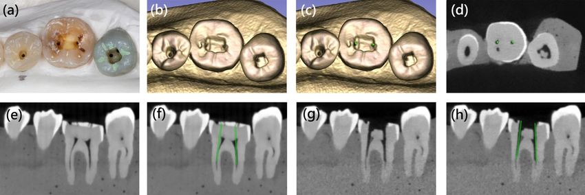
Figure 2
Superimposition of clinical, preoperative, and postoperative images: (a) Clinical photograph of right lower
first molar after enamel removal and template drilling. (b) 3D reconstruction of postoperative cone beam
computed tomography (CBCT). (c) Virtual image of burs (green cylinder) was superimposed on 3D
reconstruction of postoperative CBCT. (d) Axial view of postoperative CBCT, the vital burs (green dot)
overlapped with the paths of drills. (e) Sagittal view of preoperative CBCT. (f) Sagittal view of
preoperative CBCT with virtual burs (green cylinder). (g) Sagittal view of postoperative CBCT, and the
paths of drills penetrated into mesiolingual and distal canal. (h) Sagittal view of postoperative CBCT with
virtual burs (green cylinder). Slight deviation was noted between virtual burs and the paths of drills.
Page 13/16Figure 3
Two-dimensional schematic figure: measurement of angular and linear deviation. Red dotted cylinder:
actual bur position. Green dotted cylinder: virtual bur position. CD: coronal deviation. AD: apical deviation.
A: angular deviation.
Page 14/16Figure 4
Boxplot of linear and angle deviation. Significant differences were indicated by asterisk: (a) Coronal linear
deviation (mm) with 95% confidence interval in three groups. (b) Boxplot of apical linear deviation (mm)
in three groups. (c) Boxplot of angle deviation (°) in three groups.
Figure 5
Receiver Operating Characteristic (ROC) curves of angular deviation (blue), apical linear deviation (green),
and coronal linear deviation (yellow). Area under the ROC curve was 0.975 for angular deviation, 0.786 for
Page 15/16apical linear deviation, 0.562 for coronal linear deviation.
Supplementary Files
This is a list of supplementary files associated with this preprint. Click to download.
GraphicalAbstracts.jpg
Page 16/16You can also read