Library Part Maker 24 User Guide - Graphisoft
←
→
Page content transcription
If your browser does not render page correctly, please read the page content below

Library Part Maker 24
User Guide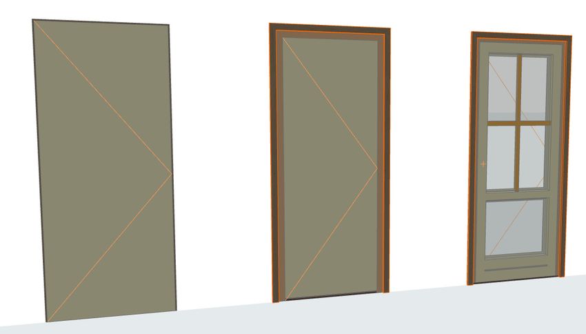
GRAPHISOFT®
  Visit the GRAPHISOFT website at www.graphisoft.com for local distributor and product
                               availability information.

                     Library Part Maker 24 User Guide
  Copyright © 2020 by GRAPHISOFT, all rights reserved. Reproduction, paraphrasing or
       translation without express prior written permission is strictly prohibited.

                                    Trademarks
                  ARCHICAD® is a registered trademark of GRAPHISOFT.
            All other trademarks are the property of their respective holders.

GRAPHISOFT UK would like to thank all participants for their valuable contributions to this
      add-on release of Library Part Maker for ARCHICAD in the UK and Ireland.
            Special thanks go to GRAPHISOFT Library Part Maker Team.
                                     Rob Kalocay
                 Product and Technical Manager for UK and Ireland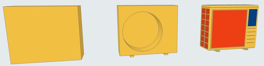
Contents
Introduction _____________________________________________________________________________ 4
Getting Started __________________________________________________________________________ 5
Library Part Maker Palette _____________________________________________________________ 6
Workflow Guide ________________________________________________________________________10
  Define Name & Design Area . . . . . . . . . . . . . . . . . . . . . . . . . . . . . . . . . . . . . . . . . . . . . . . . . . 11
  Add Library Part Components . . . . . . . . . . . . . . . . . . . . . . . . . . . . . . . . . . . . . . . . . . . . . . . . 14
  Component Assignments . . . . . . . . . . . . . . . . . . . . . . . . . . . . . . . . . . . . . . . . . . . . . . . . . . . . 16
    Select Property Scheme . . . . . . . . . . . . . . . . . . . . . . . . . . . . . . . . . . . . . . . . . . . . . . . . . . . . . 18
  Add Library Part Details . . . . . . . . . . . . . . . . . . . . . . . . . . . . . . . . . . . . . . . . . . . . . . . . . . . . . . 19
  Select Library Part Type . . . . . . . . . . . . . . . . . . . . . . . . . . . . . . . . . . . . . . . . . . . . . . . . . . . . . . 20
  Check Library Part . . . . . . . . . . . . . . . . . . . . . . . . . . . . . . . . . . . . . . . . . . . . . . . . . . . . . . . . . . . 21
  Save Library Part . . . . . . . . . . . . . . . . . . . . . . . . . . . . . . . . . . . . . . . . . . . . . . . . . . . . . . . . . . . . 23
Creating Library Parts _________________________________________________________________24
Creating Objects . . . . . . . . . . . . . . . . . . . . . . . . . . . . . . . . . . . . . . . . . . . . . . . . . . . . . . . . . . . . . . . 25
Creating Lamps . . . . . . . . . . . . . . . . . . . . . . . . . . . . . . . . . . . . . . . . . . . . . . . . . . . . . . . . . . . . . . . 26
Creating MEP Objects . . . . . . . . . . . . . . . . . . . . . . . . . . . . . . . . . . . . . . . . . . . . . . . . . . . . . . . . . . 27
Creating Doors and Windows . . . . . . . . . . . . . . . . . . . . . . . . . . . . . . . . . . . . . . . . . . . . . . . . . . . 28
Creating Skylights . . . . . . . . . . . . . . . . . . . . . . . . . . . . . . . . . . . . . . . . . . . . . . . . . . . . . . . . . . . . . . 35
Tips and Tricks _________________________________________________________________________36
Use of Attributes . . . . . . . . . . . . . . . . . . . . . . . . . . . . . . . . . . . . . . . . . . . . . . . . . . . . . . . . . . . . . . 37
Overview of LOD Assignments . . . . . . . . . . . . . . . . . . . . . . . . . . . . . . . . . . . . . . . . . . . . . . . . . . 38
Customizing Data Properties __________________________________________________________42
Create Custom Property Scheme . . . . . . . . . . . . . . . . . . . . . . . . . . . . . . . . . . . . . . . . . . . . . . . . 43
Import Property Data from Excel . . . . . . . . . . . . . . . . . . . . . . . . . . . . . . . . . . . . . . . . . . . . . . . . 44

                                                                                                                                              3
Introduction
To assist our customers, GRAPHISOFT has developed the improved Library Part Maker
(LPM), an ARCHICAD add-on that simplifies and streamlines the creation of custom GDL-
based Library Parts.
Library Part Maker focuses on delivering the ‘I’ in BIM (Building Information Modeling), in
conformity with industry standards1. The add-on uses a data driven approach while
preserving the user’s design freedom. This strongly complements GRAPHISOFT’s focus on
design freedom: giving architects the ability to create virtually anything.

BIM Library Part Concept
The concept of BIM Library Part is based on delivering building information reliably. All
components of the Library Part, such as 2D Symbol, 3D Representation and especially
information data structure, must be synchronized. Thus, changes to 2D symbols and/or 3D
models should be reflected in the Library Part’s information data structures, and vice
versa. Although GDL technology supports this approach, its implementation requires
advanced GDL programming skills that can make maintenance and redistribution
unfeasible.
The Library Part Maker workflow is based on the use of standard 2D and 3D ARCHICAD
tools, completely eliminating the need for any knowledge of GDL programming.
The LPM approach focuses on ‘real-life’ manufactured products, in which geometry and
information are firmly tied together (e.g. a certain type of product has always a unique bar
code number). Yet LPM allows for parametric 2D/3D (LOD-based) and parametric CAD
(ARCHICAD Attribute-based) 2D symbols and 3D models. Also, LPM greatly simplifies
creation and design of complex Door/Window openings in ARCHICAD.

Scope
The current release of LPM provides tools for creating the following GDL Library Part
types:
– Generic Object
– Window
– Door
– Skylight
– Lamp
– MEP Library Parts (fully functional with MEP Library 24 and the MEP Modeler Add-on,
  which is built in to ARCHICAD 24).

   1.such as BS8541-1/2/3 in UK

                                                                                              4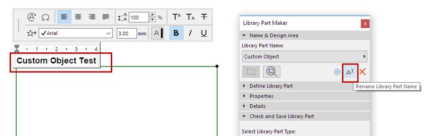
Getting Started
Installation
1. Close all running instances of ARCHICAD
2. Run the Installer package.
3. Restart ARCHICAD.
4. From the New Project dialog, choose the Library Part Maker Template 24.

Templates
Library Part Maker can be used with the standard local ARCHICAD template.
In addition, the Library Part Maker Template 24 contains examples of LPM library
elements, including MEP elements.
To use a template, start a New Project in ARCHICAD and browse the folder of available
templates (Defaults\ARCHICAD folder).

Migration
LPM for ARCHICAD 24 removes the layer-based functionality of previous LPM (ARCHICAD
19 and 20) releases and replaces it with the Assignment-based concept. This concept
removes the rigid organization of elements by layers, a process that could be error prone
and heavily dependent on the LPM Template.
The new workflow is based on the upgraded and integrated Library Part Palette.
Any content created by LPM release prior to ARCHICAD 24 will be automatically migrated
to appropriate assignments. These elements can be freely moved to any layer.
The creation of Handles and Shutter accessories as separate Types has been
discontinued. These Library Parts are covered by a standard ARCHICAD functionality in File
> Libraries and Objects > Save Selection As.

                                                                                         5
Library Part Maker Palette
All commands needed for creating a Library Part are now available on a single Library Part
Maker palette.
See Workflow At A Glance.

Open Library Part Maker Palette
Open the palette using one of these commands:
– Design > Design Extras > Library Part Maker
– Window > Palettes > Library Part Maker

Selection and Highlight
Use the Palette icons to help you identify and select to particular Library Parts and
components:

Zoom to a Design Area
1. Select a Library Part Name from the pop-up.
2. Click the Zoom button to zoom to its Design Area on the Floor Plan

                                                                                         6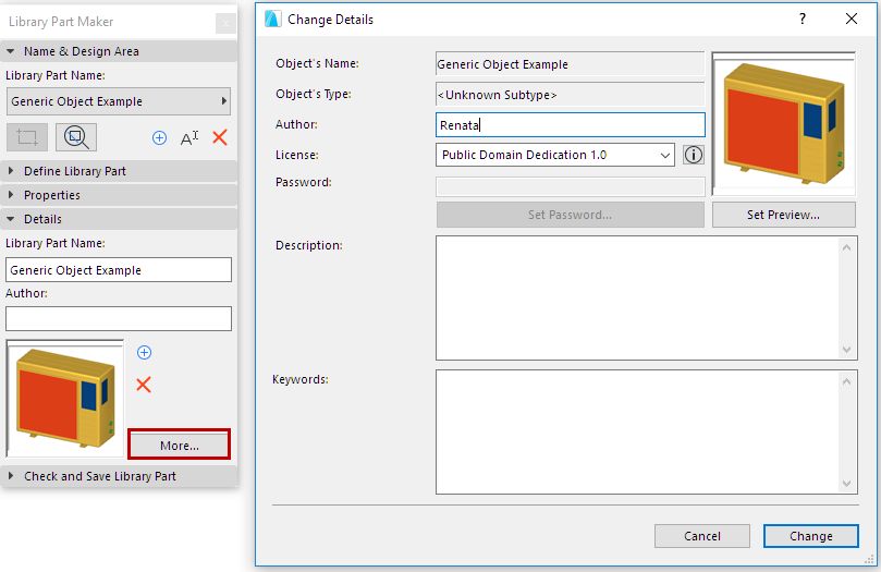
Select Components by Type
1. Select a Component Type from the pop-up (e.g. 2D Symbol Reflected Ceiling Plan)
2. Click the Select Components button.

All Components of this type are now selected on the plan.

Highlight Components by Type
1. Select a Component Type from the pop-up (e.g. 3D Model Full)
2. Click the Highlight Components toggle button.

                                                                                     7
All Components of the selected type are now highlighted on the plan.

To remove the highlight, click the Highlight Components button again.

Highlight Unassigned Components
– Select the Not Assigned Component Type from the pop-up
– Click the Highlight Components toggle button.

                                                                        8
All Components on the plan that have not been assigned a type are now highlighted.
To remove the highlight, click the Highlight Components button again.
Set Highlight Colors
Click the pop-up next to the Highlight preview to access its color setting interface. You can
set a separate color for not assigned components, as well as Transparency (this is useful in
the 3D window).
9Workflow Guide
Workflow At A Glance
Use the controls of Library Part Palette from top to bottom to design your new Library Part.
Add new Library Part Name
1.
Use whatever is on your mind…
Define the Design Area for your Library Part
2.
Mark the workspace in which you will design the Library Part
Components
Start adding components for each Detail Level
3.
Draw the 2D and 3D model symbols
Select Property Scheme
4.
Which listing parameters should the Library Part use?
Add Details
5.
Define a Preview, add other info... don't forget the author!
Specify Library Part Type
6.
Is it a Door, a Window, an Object?
Check your Library Part
7.
Verify your creation, and fix any issues.
Customize Parameter and Attributes
8.
Open the popup, where you can refine parameters and attributes
(names, values, defaults)
Save it (Finally!)
9.
And it's ready to place.
Each step is explained in the sections that follow.
10Define Name & Design Area
The first step is to create a Library Part Name and draw its Design Area on the Floor Plan.
1. In the Library Part Maker palette, do one of the following:
• Click the Plus sign.
• From the LibPart Name pop-up, choose Add New Library Part Name.
2. In the appearing dialog, assign a name.
3. Click Mark Design Area.
114. Click on the Floor Plan to draw a Design Area frame. The name is displayed next to the
frame automatically.
You can also create new Design Areas by copy-pasting an existing Design Area (e.g. in a
matrix). Each copy is automatically given a new name and listed separately in the Palette’s
pop-up.
What is a Design Area?
– The Design Area contains the 2D and 3D elements (components) which constitute the
Library Part. The Design Area groups these components and their attributes, and
preserves any modifications you make along the way.
– The Design Area can be added before or after creating the current Library Part.
– The Check and Save function considers the current Design Area content when checking
the validity of the library part.
– Deselecting the Design Area or any of its parts will not result in lost changes.
See also Zoom to a Design Area.
Add New Design Area
If the Design Area frame is deleted, the Library Part Name is still available in the palette,
but you will not be able to save it: when you run a check, you will get a warning.
To draw a new Design Area, click the Add Design Area icon and draw it again.
12Rename Library Part Name
Do one of the following:
– Edit the Library Part name directly on the Floor Plan
– Click the Rename button on the palette.
13Add Library Part Components
Inside the Design Area, use 2D and 3D tools to draw the components of the Library Part.
Note: To focus on a particular Design Area on the Floor Plan, use the Zoom function
from the LPM Palette: see Zoom to a Design Area.
The LPM Template examples contain the 3D model components in the top row (with LOD
increasing from left to right), and the 2D symbols in the bottom row.
Design Principles for 2D Symbols
– Draw 2D symbol(s) using any 2D ARCHICAD tool (except Text tool).
For a door/window, the 2D symbol orientation must be aligned with horizontal axis (x).
The external face of opening should face up (see Examples of 2D Symbol Level of Detail).
– Use Hotspot Tool to define custom 2D hotspots (effective for 2D Symbols only)
– Assign a content origin to each component (see Define Component Origins (Place Level
Dimensions)
– Any Library Parts used in your 2D symbols should be exploded to 2D primitives (lines,
arcs, polylines etc.)
14Define Component Origins (Place Level Dimensions)
For each component (both 2D Symbol and 3D Model), use the Level Dimension Tool to
place a Content Origin. This is used to align the 2D Symbol and 3D Model content when
the Library Part is saved.
The origin can be placed at any position as long as it is aligned with other component
origins. The recommended approach is to place the origin in the center of an object, or (in
case of irregular 2D symbols and 3D models) its bounding box.
The origin must be assigned a component type for each used 2D Symbol and 3D model.
See Door/Window Component Origins.
15Component Assignments
For each component, assign its Level of Detail (LOD) using the Component Type pop-up on
the LPM Palette. Each type represents a 2D or 3D representation at a particular detail
level:
See also Highlight Components by Type.
Once the Library Part is saved and placed, these assigned LOD representations can be
controlled for each placed instance – either from its Settings dialog, or from ARCHICAD’s
Model View Options.
It is possible to skip the LOD definition for some components; these components have a
definition of “Not Assigned”. (When you check the Library Part, you get a warning of
unassigned components, but you can still save it.) When placed, such Library Parts will use
only the defined representation. However, this practice is not recommended as it can lead
to unexpected 2D/3D representations of Library Part in documentation and 3D model
views with certain scale or Model View Options settings.
See also Highlight Unassigned Components.
Add Components Using Current Type
To create multiple components with a particular Component type:
1. Choose the desired Component type from the pop-up (e.g. 2D Symbol Full)
2. Click the Start/Stop Adding Components toggle button.
16All the components you add now will automatically be assigned the current Component
type, until you click the toggle again.
Assignments for 3D Model Components
LPM Assignment Content shown with corresponding Model View Option
(MVO) at:
– Detail Level of Door, Window and Skylight Symbols
– Miscellaneous Settings for Library Parts
3D Model Full 3D and Section/Elevation: Full
3D Model Simplified 3D and Section/Elevation: Simplified
3D Model Schematic 3D and Section/Elevation: Schematic
Assignments for 2D Symbol Components
LPM Assignment Content shown with corresponding Model View Option
(MVO) at: Miscellaneous Settings for Library Parts
2D Symbol Full Floor Plan Realistic Full
2D Symbol Medium Floor Plan Realistic Medium
2D Symbol Low Floor Plan Realistic Low
2D Symbol Electrical Lighting and HVAC Floor Plan Symbol: Electrical
2D Symbol Reflected Lighting and HVAC Floor Plan Symbol: Reflected Ceiling Plan
Ceiling Plan
Please note that 2D Electrical and Reflected Ceiling Plan assignments are ignored for MEP
objects.
17Select Property Scheme
The new Library Part must include a set of listing properties. These listing properties will be
available in the Descriptions area (Custom Settings panel) in the Settings dialog of the
saved Library Part.
To define the Library Part’s listing properties:
In the Properties panel, select an option to define the Library Part’s listing properties:
– Property Scheme
– Spreadsheet
Default Property Scheme
To populate the list for newly created objects, Library Part Maker uses the “ARCHICAD
Listing Parameters scheme” by default.
If your template includes other built-in schemes, you can also choose among those.
– You can create any custom parameter scheme instead.
– A custom scheme together with defined values can be imported directly from an Excel
spreadsheet.
See Customizing Data Properties for details on creating or importing a custom scheme.
18Add Library Part Details
In the Details panel, add optional authoring and other metadata (Author, License,
Password for script locking, Preview image, Description and Keywords).
Click More to open the Change Details dialog, with all available options.
Add Preview Picture
Remove Preview Picture
Open Change Details Dialog
19Select Library Part Type
In the Check and Save Library Part panel:
Choose an option from the Select Library Part Type drop-down.
If you choose MEP Library Part, an additional pop-up appears: You must further specify the
MEP type.
20Check Library Part
You cannot save the current Library Part until you check it.
In the Check and Save Library Part panel, press Check.
The check is run on the Design Area of the current Library Part Name.
Review Issues
Review the displayed issues (alerts, warnings) that could affect or prevent saving of Library
Part. Correct any issues that require it.
– Green checkmark: No issues found. Review the parameters, then Save.
– Yellow warning: This calls your attention to an anomaly, but this does not prevent you
from saving the Library Part. Review the parameters, then Save.
– Red warning: This is an error which must be fixed before you can continue.
21Adjust Parameters and Attributes
Once the Check produces no warnings that require fixing, the Parameters pop-up is
available. Here, you see the parameters and attributes that will be saved with the current
Library Part.
The attributes (line types, pens, fills, surfaces, building materials) are those used in the 2D
symbols and 3D models of the Design Area. The parameter names are automatically
derived from the name of the current project Attributes.
You can edit the names and values here. The Design Area will remember the parameter
changes you make.
22Save Library Part
Click Save as.
Note: This command is only available after you have run the Check, and provided that
the Check produced no warnings that require fixing. (See previous section.)
In the Save dialog which appears, enter a name and choose the desired folder location for
the object:
– to the Embedded Library (default choice. It is recommended to save customized,
project-specific objects to your Embedded Library.)
– browse for a linked library or a BIMcloud library that has been added to the project
Note: In Teamwork, you must reserve the BIMcloud Library folder before saving to it.
23Creating Library Parts
The following sections list the relevant Assignments for each Library Part type. In addition,
they provide more details on what to consider when creating Library Parts of a particular
type.
Creating Objects
Creating Lamps
Creating MEP Objects
Creating Doors and Windows
Creating Skylights
24Creating Objects
Level of Detail Definition for Objects (similar to Lamps)
These tables specify how the placed object will be displayed depending on its Object
Settings (Symbol Type, Detail Level, etc.)
The Default LOD is taken from the Library Part Maker assignments. If a certain assignment
is undefined, the “Substitute” value is used.
Selected Symbol Type Default LOD Substitute LOD 1
Realistic Selected 2D Detail Level ---
Electrical Electrical Symbol Selected 2D Detail Level
Reflected Ceiling Plan Reflected Ceiling Plan Selected 2D Detail Level
Symbol
Selected Default LOD Substitute Substitute Substitute
2D Detail Level LOD 1 LOD 2 LOD 3
Full Full Medium Low System 2D
bounding box
Medium Medium Low Full System 2D
bounding box
Low Low Medium Full System 2D
bounding box
Selected Default LOD Substitute Substitute Substitute
3D Detail Level LOD 1 LOD 2 LOD 3
Full Full Simplified Schematic 3D not shown
Simplified Simplified Schematic Full 3D not shown
Schematic Schematic Simplified Full 3D not shown
System predefined parameters for Objects
Dimension 1 – Overall object size along X axis
Dimension 2 – Overall object size along Y axis
Height – Overall object size along Z axis
25Creating Lamps
Level of Detail definition of Lamps (similar to Objects)
Selected Symbol Type Default LOD Substitute LOD 1
Realistic Selected 2D Detail Level ---
Electrical Electrical Symbol Selected 2D Detail Level
Reflected Ceiling Plan Reflected Ceiling Plan Selected 2D Detail Level
Symbol
Selected Default LOD Substitute Substitute Substitute
2D Detail Level LOD 1 LOD 2 LOD 3
Full Full Medium Low System 2D
bounding box
Medium Medium Low Full System 2D
bounding box
Low Low Medium Full System 2D
bounding box
Selected Default LOD Substitute Substitute Substitute
3D Detail Level LOD 1 LOD 2 LOD 3
Full Full Simplified Schematic 3D not shown
Simplified Simplified Schematic Full 3D not shown
Schematic Schematic Simplified Full 3D not shown
Additional components/assignments
At least one light source, with an assignment of 3D Model Full, must be defined for each
Lamp-type Library Part.
Light source Library Parts are located at ARCHICAD Library 24 > General Light Sources.
26Creating MEP Objects
Level of Detail definition of MEP Objects
Selected 2D Default LOD Substitute Substitute Substitute
Detail Level LOD 1 LOD 2 LOD 3
Full Full Medium Low System 2D
bounding box
Medium Medium Low Full System 2D
bounding box
Low Low Medium Full System 2D
bounding box
Selected 3D Default LOD Substitute Substitute Substitute
Detail Level LOD 1 LOD 2 LOD 3
Full Full Simplified Schematic 3D not shown
Simplified Simplified Schematic Full 3D not shown
Schematic Schematic Simplified Full 3D not shown
Additional components/assignments
– For MEP objects, 3D Representation requires the use of the MEP Connection object
(which can be found in MEP Library > MEP Connection), in order to facilitate the
automatic connectivity of MEP objects.
– This MEP Connection component must be assigned to 3D Model Full.
– For Duct/Pipe Inline Flow Library Parts, there must be at least 2 MEP Connections,
assigned to 3D Model Full. These must be placed on a single axis facing in opposite
directions.
– When creating a Duct or Pipe MEP Library Part, make sure that the MEP Connection
component is assigned the corresponding Connection Class: Duct or Pipe.
27Creating Doors and Windows
Level of Detail definition of Doors and Windows
Selected Default LOD Substitute Substitute Substitute
2D Detail Level LOD 1 LOD 2 LOD 3
Full Full Medium Low System empty
opening
Medium Medium Low Full System empty
opening
Low Low Medium Full System empty
opening
Selected Default LOD Substitute Substitute Substitute
3D Detail Level LOD 1 LOD 2 LOD 3
Full Full Simplified Schematic System empty
opening
Simplified Simplified Schematic Full System empty
opening
Schematic Schematic Simplified Full System empty
opening
Door/Window Component Origins
A special methodology applies in case of Door and Window Library Parts.
– Component origins for 2D door/window symbols must be aligned with the center of
door/window wall opening and the external edge of wall they will be placed in.
– Component origins for 3D door/window models must be aligned with the bottom
center of door/window wall opening.
28Door Symbol with Component Origin at Hotspot
Additional components/assignments
Definition of Door/Window Tolerance
LPM Assignment Content shown with corresponding Model View Option
(MVO): Detail Level of Door, Window and Skylight Symbols
2D Tolerance Full Floor Plan Symbol Full
2D Tolerance Medium Floor Plan Symbol Medium
2D Tolerance Low Floor Plan Symbol Low
The Wallhole is the part cut out of the wall to accommodate the whole door/window
structure.
Wallhole Width is equal to Unit Dimension Width plus any Horizontal Tolerance.
Wallhole Height is equal to Unit Dimension Height plus any Vertical Tolerance.
Tolerance Values in Door Custom Settings
29Design Principles of Tolerance
The tolerance 2D symbol must always be drawn (using ARCHICAD 2D tools) on the left-
hand side of the door/window 2D symbols, with the same width for all used 2D symbols in
a door/window Library Part.
The 2D tolerance symbols will be automatically added to right, top and bottom door/
window edges, and they will be parametrically adjusted to Wallhole edges. The 3D model
will be created automatically, based on the tolerance width defined in 2D Symbol and the
door/window frame thickness. The tolerance width and tolerance surfaces will be
automatically added to the door/window user interface as parametric values.
Tolerance Width Tolerance Width Tolerance Width
Tolerance Displayed at Low, Medium and Full LOD Assignment
30Opening Lines, Hinges and Handles
LPM Assignment Content shown with corresponding Model View Option
(MVO): Miscellaneous Settings for Library Parts
Opening Line Hinges Full Show Opening Line (Hinges orientation, Full 3D)
Opening Line Hinges Show Opening Line (Hinges orientation, Simplified 3D)
Simplified
Opening Line Hinges Show Opening Line (Hinges orientation, Schematic 3D)
Schematic
Opening Line Handle Full Show Opening Line (Handle orientation, Full 3D)
Opening Line Handle Show Opening Line (Handle orientation, Simplified 3D)
Simplified
Opening Line Handle Show Opening Line (Handle orientation, Schematic 3D)
Schematic
Design Principles of Opening Lines, Hinges and Handles
Handle Opening Line orientation Hinges Opening Line orientation
LPM allows to define any number and directions of Opening Lines and/or Opening
Operation symbols in 3D Models by using 3D ARCHICAD tools. The 3D opening lines can
be defined by Morph tool (set to the Line Geometry Method).
It is also possible to use e.g. the 3D Text Library Part (from standard ARCHICAD library) to
define any fixed text annotations.
Considering the varying standards for the direction of opening lines, LPM provides 2 sets
of assignments that define opening line orientation as either “Hinges” or “Handle”.
The Opening Line Orientation control (available in Model View Options and the Library
Part user interface) allow the user to flip their positioning as needed.
Positioning of Door/Window Handle Assembly
Note that the option for 3D Handle assembly is available for “3D Model Full” LOD only.
LPM Assignment Content use
Handles Internal Full Used for Handle assembly on internal face of opening
Handles External Full Used for Handle assembly on external face of opening
31LPM allows definition of any number and directions of Handle assembly types, separate
for interior and exterior faces of an opening. The type of Handle assembly can be selected
from standard ARCHICAD types or any Custom Component Handle Library Parts (in loaded
libraries).
Design Principles of Handle Positioning
Use the 3D lines that can be defined by Morph tool (set to the Line Geometry Method)
Definition (Morph line)
Morph Origin
The morph origin will be used as the anchor point (in 3D space, so the morph line must be
positioned on door/window surface), and the direction of the line will be used as the
Handle assembly’s orientation. The length of the line does not affect the final handle
position or shape. The relationship of a morph line used for design and the final Handle
model is illustrated below:
The assignment type will define handle orientation with regards to Internal or External face
of a door or window.
See Door/Window Component Origins.
32Door and Window Standard Fixtures and Fittings
The following standard ARCHICAD library door or window parametric elements and
functionality will be added to each door or window automatically:
Windows
– Wall Opening – Reveal
– Wall Opening – Wall Closure
– Wall Opening – Wall Inset
– Wall Opening – Masonry Arch
– Wall Opening – Attributes
– Fixtures & Fittings – Sill
– Fixtures & Fittings – Board
– Fixtures & Fittings – Casing Inside/outside
– Fixtures & Fittings – Sunshade
– Fixtures & Fittings – Custom Corner
– Fixtures & Fittings – Attributes
Door
– Wall Opening – Reveal
– Wall Opening – Wall Closure
– Wall Opening – Masonry Arch
– Fixtures & Fittings – Threshold
– Fixtures & Fittings – Casing Inside/outside
– Fixtures & Fittings – Sunshade
– Fixtures & Fittings – Attributes
System predefined parameters for Doors and Windows
– Width – width of Door/Window set
– Height – height of Door/Window set
– Nominal Frame Thickness – frame thickness of Door/Window set
– Orientation Displaying – If set to ‘Automatic’, Label Default Position and Label Reversed
Position values will be used for Door/Window labels and in Interactive Schedules. If set
to ‘Custom’, the value of Custom Orientation parameter will be used instead.
– Custom Orientation – used in conjunction with Orientation Displaying parameter
– Label Default Position – (set to ‘L’ for ‘Left’ by default) used in conjunction with
Orientation Displaying parameter
– Label Reversed Position – (set to ‘R’ for ‘Right’ by default) used in conjunction with
Orientation Displaying parameter
33– IFC Operation – IFC operation definition
– Surfaces > Door/Window Tolerance Outer Surface – outer surface of tolerance infill
– Surfaces > Door/Window Tolerance Inner Surface – inner surface of tolerance infill
– Surfaces > Door/Window Handle Surface – surface of Door/Window handle(s)
– Pens > Opening Line Pen – pen of Door/Window opening lines
34Creating Skylights
The same methodology applies as in case of Door and Window for 3D Representation. The
2D Symbol will be automatically created by the system as 2D projection of 3D
Representation.
Level of Detail definition of Skylights
Selected 2D Detail Default LOD Substitute LOD 1 Substitute LOD 2
Level
Full System 3D projected System 3D projected System 3D projected
Full Medium Low
Medium System 3D projected System 3D projected System 3D projected
Medium Low Full
Low System 3D projected System 3D projected System 3D projected
Low Medium Full
Selected 3D Detail Default LOD Substitute LOD 1 Substitute LOD 2
Level
Full Full Simplified Schematic
Simplified Simplified Schematic Full
Schematic Schematic Simplified Full
Additional components/assignments
Skylight Opening Lines
These are the same as Door/Window Opening Lines.
LPM Assignment Content shown with corresponding Model View
Option (MVO): Miscellaneous Settings for Library
Parts
Opening Line Hinges Full Show Opening Line (Hinges orientation, Full 3D)
Opening Line Hinges Simplified Show Opening Line (Hinges orientation, Simplified 3D)
Opening Line Hinges Schematic Show Opening Line (Hinges orientation, Schematic 3D)
Opening Line Handle Full Show Opening Line (Handle orientation, Full 3D)
Opening Line Handle Simplified Show Opening Line (Handle orientation, Simplified 3D)
Opening Line Handle Schematic Show Opening Line (Handle orientation, Schematic 3D)
35Tips and Tricks
Use of Attributes
Overview of LOD Assignments
LOD Recommendations
36Use of Attributes
It is recommended to consolidate and check the ARCHICAD tools’ attribute settings before
you draw or model Library Part definitions. This will help you avoid unwanted attributes as
parameters in the Library Part user interface.
Setting up your tool attribute settings in the Favorites palette is the best way to minimize
errors and avoid the laborious process of checking the tool attribute settings every time.
37Overview of LOD Assignments
Objects, Lamps and MEP Objects
Assignment
Duct In-line Flow Device
Pipe In-line Flow Device
Duct Flow Terminal
Pipe Flow Terminal
Flow Equipment
Duct Fitting
Pipe Fitting
Object
Lamp
2D Symbol Full + + +1 +1 + + +1 +1 +
2D Symbol Medium + + +2 +2 + + +2 +2 +
2D Symbol Low + + + + + + + + +
2D Symbol Electrical + +
2D Symbol Reflected Ceiling Plan + +
3D Model Full + + + + + + + + +
3D Model Simplified + + + + + + + + +
3D Model Schematic + + + + + + + + +
1.Projected from 3D Model Full (or Simplified, if no Full is defined)
2.Projected from 3D Model Simplified (or Schematic, if no Simplified defined)
38Doors, Windows and Skylights
Assignment
Window
Skylight
Door
2D Symbol Full + +
2D Symbol Medium + +
2D Symbol Low + +
3D Model Full + + +
3D Model Simplified + + +
3D Model Schematic + + +
2D Tolerance Full + +
2D Tolerance Medium + +
2D Tolerance Low + +
Opening Line Hinges Full + + +
Opening Line Hinges Simplified + + +
Opening Line Hinges Schematic + + +
Opening Line Handle Full + + +
Opening Line Handle Simplified + + +
Opening Line Handle Schematic + + +
Handles Internal Full + + +
Handles External Full + + +
LOD Recommendations
Recommended 2D Symbol Level of Detail
Consider the pen thickness and detail appearance at scale – too detailed 2D
representations for larger scales might be difficult to read.
39Examples of 2D Symbol Level of Detail
Window: Low, Medium, Full LOD Assignments
Door: Low, Medium, Full LOD Assignments
Object: Low, Medium, Full LOD Assignments
Recommended 3D Model Level of Detail
Creating very detailed 3D models can lead to a heavy polygon count that can slow down
ARCHICAD. Here are some hints to help you create Library Parts without compromising
performance:
– Avoid modeling details legible at scales less than 1:20 in general (e.g. 1:10 or 1:5 etc.)
– Simplify shapes of frame/sashes sections or assembly profiles
– Do not model unnecessary elements (if possible) such as door/window seals, detailed
door/window ironmongery, fasteners and similar.
– Avoid creating an excessive number of curved surfaces.
– Creating curved surfaces with very small radii will result in faceted faces; the best
approach is to simplify them. (A typical example for the simplification use would be
extruded steel/aluminum profiles of door or window frames and sashes).
– Use the Morph tool (plane with zero thickness) for elements that should appear as a
single line in Sections (e.g. glazing panes or door leaf/window sash in “Schematic” 3D
LOD).
40Examples of 3D Model Level of Detail
Window: Schematic, Simplified, Full LOD Assignments
Door: Schematic, Simplified, Full LOD Assignments
Object: Schematic, Simplified, Full LOD Assignments
41Customizing Data Properties
Create Custom Property Scheme
Import Property Data from Excel
42Create Custom Property Scheme
You must create a new Library Object, with the desired parameter definitions, and save it
to a loaded library in your project.
Follow these steps:
– Create a new Library Part: File > Libraries and Objects > New Object…
– In the appearing Object Editor window, click Select Subtype.
– From the Subtype Hierarchy dialog, choose “LPM Listing Definition”, and click Select.
– Back in the Object Editor window, uncheck Placeable.
– In the Object Editor, use the Parameters control to define parameter names and their
types.
– Use File > Save to save the Library Part (your new Property Scheme) to a project library.
– In Library Manager, reload your project libraries (File > Libraries and Objects >
Library Manager…)
The new Listing Definition scheme will appear in the drop-down menu of Property
Schemes, in the Library Part Maker palette.
43Import Property Data from Excel
To see a sample Excel spreadsheet containing a Property Scheme:
Go to
– GRAPHISOFT > ARCHICAD24 > Add-ons > Extras > LibraryPartMaker folder
and browse for
– Library Part Maker Property Schedule Template 24
The spreadsheet must be formatted to the columnar format with standard column header
names as follows:
Property Group
Used for grouping parameter headers in Library Part parameter definitions
Property Name
Used for parameter names, truncating the actual name to 28 characters
ARCHICAD Data Type
Values in this column define ARCHICAD GDL parameter types. The definition values are
limited to the following types:
– Boolean
– Real
– Integer
– Text
– Length
– Angle
The property value sets are defined by the column and will be used in the LPM’s Choose
values to Import drop-down list.
44You can also read