Microwave Calorimeters - For Traceable Power Measurements - University of Colorado Boulder
←
→
Page content transcription
If your browser does not render page correctly, please read the page content below
Microwave Calorimeters
For Traceable Power Measurements

 Ryan Brink       Megan Borfitz        Austin Hegemann         Paris Buedel
Project Manager   Logistics Manager   Manufacturing Engineer    CAD Engineer

     Chase Greenberg         Sophia Henze         Paul DiTomas
       Systems Engineer     Financial Manager       Test Engineer
                                                                               1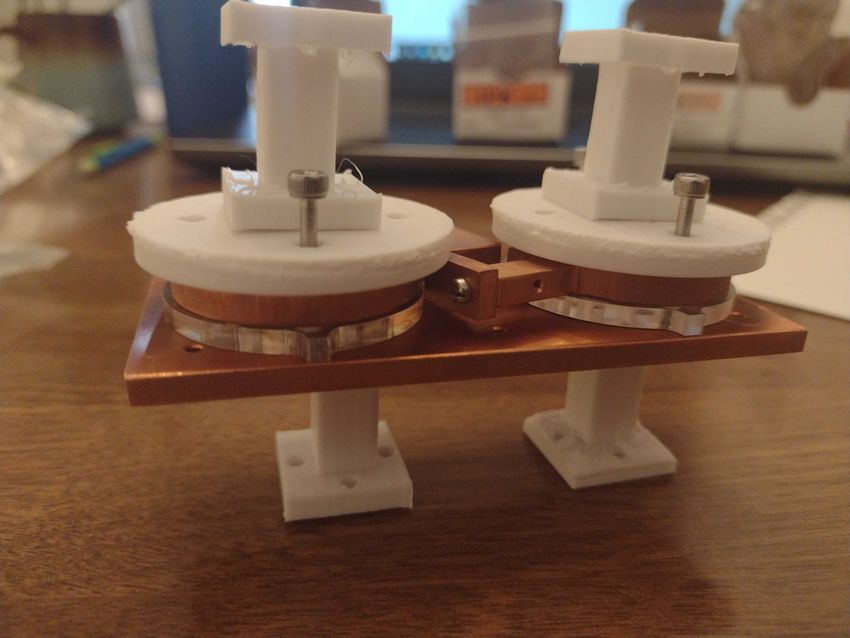
Contents

Executive Summary           3

Background and Motivation   4

Project Goals               5

Thermal Simulations         6

Manufacturing               7

Assembly                    8

Cost Analysis               9

Meet the Team               10

                                 2
Executive Summary
Measurement standardization is crucial to technological advancement as it helps ensure that
components work together correctly, both nationally and internationally. The National Institute of
Standards and Technology (NIST) standardizes certain measurement techniques by maintaining
traceability for these measurements. A traceable measurement can be compared to international
standards (ultimately, the definitions of the SI units) with an unbroken chain of calibrations, each with
well-defined uncertainties. NIST Boulder’s RF Technology Division characterizes power sensors so that
they measure microwave power in a way that is consistent with the basic definition of the milliwatt. They
do this using a process called traceability. By making precise, traceable measurements, all uncertainties
in those measurements can be related back to a reference point.1
Our job for this project was to assist our client’s understanding of this device and then enhance its design.
We used finite element analysis to determine the correction factor in the microcalorimeter and more fully
understand the sources of uncertainty. Then, we redesigned and manufactured a new microcalorimeter
model which aimed to reduce uncertainty in the design. Our new design is expected to improve
connection repeatability while reducing the manufacturing cost by 85%.
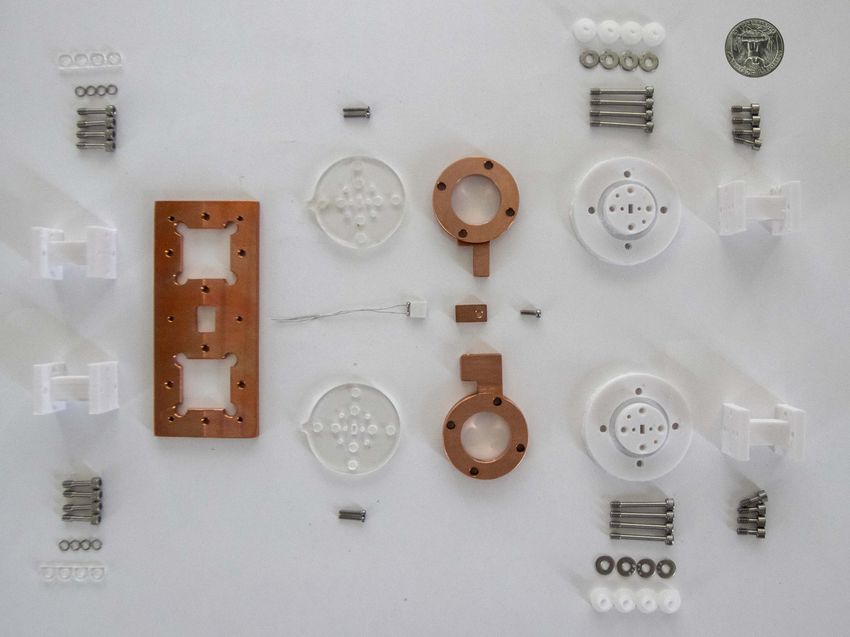
NIST's Original Calorimeter Our Final Redesign
1“Supplementary Materials Related to NIST Policy on Metrological Traceability.” NIST , National Institute of Standards and Technology,
10 Sept. 2019, www.nist.gov/traceability/supplementary-materials-related-nist-policy-metrological-traceability#faq general1. 3
Background
In order to characterize power sensors to accurately
measure microwave power, NIST uses a device
called a microcalorimeter. Unlike a typical
calorimeter which measures energy in Joules, a
microcalorimeter instead measures microwave
power in milliwatts. Despite this distinction, we will
be referring to the microcalorimeter as a
‘calorimeter’ for brevity.
There are several types of microcalorimeters that
vary based on their overall design and the
microwave frequency they can handle. During our
project, we worked with the twin-load type
calorimeter.                                              Basic components of a twin-load microcalorimeter
                                                              Photo credit: NIST (labels added in post)

                                                         Functionality
                                                         The twin-load type calorimeter core has two
                                                         nearly identical halves. One half contains the
                                                         device under test (DUT) and the other half
                                                         contains the reference sensor. The only
                                                         differences between the two sides are that the
                                                         clamping mechanism that connects them is not
                                                         symmetrical and one side receives power
                                                         while in operation. During operation,
                                                         microwave power is sent into the DUT, while
                                                         no power is sent to the reference side. The
                                                         DUT absorbs microwave power via the
                                                         thermistor and heats up the sensor. The
                                                         reference side receives no power and remains
                                                         cool. Therefore, heat flows from the DUT,
                                                         through the thermopile, and to the reference
                                                         side, thus creating a temperature difference
  Microwave power input and heat flow of twin-
                                                         across the thermopile. The thermopile
         load calorimeter in operation
                                                         measures the temperature difference between
                                                         the DUT and reference side which NIST uses
                                                         to calculate the microwave power.

                                                                                                          4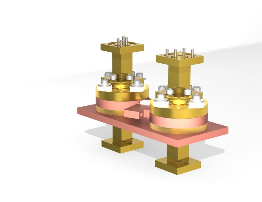
Project Goals
Thermal Simulation
The thermistor's resistance depends on
temperature. When the thermistor absorbs
microwave power, it heats up. In this way,
microwave power can be detected through DC
resistance measurements. Not all of the
microwave is absorbed in the thermistor bead;
some is reflected back through the waveguide,
and some is absorbed through the walls of the
calorimeter. One of our clients' biggest
                                                          Our redesigned calorimeter featured more
challenges was determining where heat                    commercial parts which are easier to replace.
dissipates inside the calorimeter. We used the
COMSOL Multiphysics FEA program to obtain a              Design and Manufacture
more accurate understanding of the heat
dissipation and its relationship to the correction       After completing our clients' initial project
factor. Initially, this was our clients’ original goal   request, we addressed some of the
for the project. Since we were able to complete a        shortcomings in the current calorimeter design
thermal simulation that satisfied NIST’s needs in        by redesigning it to be more modular.
the first semester, we moved on to
manufacturing in the second semester.                    Our clients expressed that one major area of
                                                         concern in the old calorimeter design is
                                                         connection repeatability, which we had not
                                                         considered in our thermal simulation.
                                                         Frequently reassembling the calorimeter
                                                         causes wear between the precision
                                                         components, meaning experimental results
                                                         can deviate between tests based on the
                                                         conditions of the pieces. Therefore, it is
                                                         important to replace the components as they
                                                         become worn. However, the original
                                                         calorimeter consists of many expensive parts
                                                         that are custom-made and difficult to replace.
                                                         Thus, one of our goals for the second
                                                         semester was to design a calorimeter with
                                                         more commercially available components.

  We simplified the calorimeter's original
  geometry, removing features that were
  inconsequential to the thermal analysis.                                                                5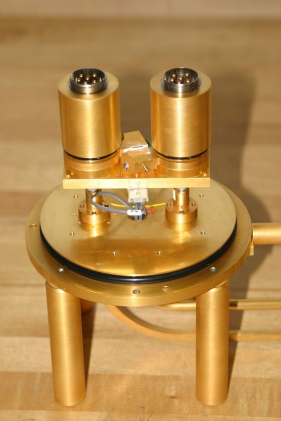
Thermal Simulations

   Surface temperature plot of microcalorimeter given           Surface temperature plot in the walls of the
              variable heat flux parameter                     waveguide given variable heat flux parameter

Building the Model                                      Electromagnetic Boundary Conditions
Our first task was to create a thermal simulation       We advanced our model further by replacing the
of the microcalorimeter under load to determine         constant heat flux in the waveguide with a variable
where heat loss and uncertainty were                    heat flux that more closely represented the
occurring. We started by simplifying the                microwave's behavior. We modeled the propagation of
geometry in SolidWorks, which made the                  microwaves in the waveguide to determine where heat
thermal model more manageable. We then                  was dissipated.
began learning the basics of COMSOL. Once
we understood the correct file types and the            We again measured the temperature difference across
basics of meshing, we continued by modeling             the thermopile which allowed us to determine its
one half of the calorimeter core. We applied the        correction coefficient value of 0.0041, which is realistic
corresponding material properties and                   based on measurements of similar calorimeters. We
boundary conditions.                                    ran tests on our simulation by changing factors such
                                                        as geometric dimensions and boundary conditions to
Next, we imported a more complex model and              see how they affected the correction factor and thus
determined more realistic boundary conditions.          optimized the design of the calorimeter to reduce the
We modeled the full twin assembly which                 uncertainty. This new geometry became the starting
included both the dummy and the DUT, as well            point for our redesign during the spring semester.
as the thermopile in between the two halves.
Finally, we applied constant heat flux boundary
conditions, with which we could then determine
                                                             Top view of calorimeter:
the temperature gradient across the thermopile.                  surface temperature
This is one of the crucial measurements for                  across the thermopile in
                                                            simulation given variable
determining microwave power.
                                                                  heat flux parameter

                                                                                                                     6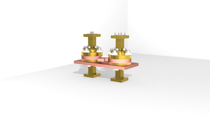
more precise connections with the waveguides.
                                                         Unfortunately, these changes required excessive
                                                         precision manufacturing. Thus, our final design
                                                         incorporated custom bulkhead adapters and
                                                         numerous commercial components thereby
Manufacturing                                            improving manufacturability and hopefully connection
                                                         repeatability.

At the start of the spring semester, we transitioned     A final point of design iteration involved improving the
from working on the thermal simulations to designing     isolation section, which plays a key role in creating a
and manufacturing an improved WR-15 calorimeter.         thermal boundary between the upper measurement
We went through six major design iterations before       section of the calorimeter and the lower waveguide
deciding to move forward with manufacturing the          section. A thicker isolation section prevents unwanted
final version.                                           thermal dissipation but also gives a higher correction
                                                         factor.
Our first design was similar to the previous
calorimeter model. The main improvement was fitting      Eventually, we decided to reduce the isolation
a bulkhead adapter into the interface plate.             section thickness from 0.25” to 0.125” and change
Originally, the interface plate had a waveguide slot     the material from ABS to acrylic. The geometric
through the center, which required inside right angles   change in thickness was made due to dimensional
and are difficult and expensive to manufacture. Our      constraints of the overall calorimeter, and the
new design instead fits the bulkhead adapter, a          material change was made because we decided to
commercially available part, into the interface plate.   laser cut the isolation section instead of 3D print it.
This accomplishes the thermal role of the interface      Our simulations concluded that making the isolation
plate, eliminates the need to custom-machine inside      section smaller results in the added benefit of a lower
corners in the interface plate, and reduces the total    correction factor, but also reduces the difference in
number of connection points, improving connection        voltage across the thermopile, possibly making the
repeatability.                                           system more susceptible to noise. Laser cutting the
                                                         part results in tighter tolerances and faster production
Our later iterations modified the geometry to create     than 3D printing.

                                                                                            Key design changes
                                                                                            between the original
                                                                                            design and our final
                                                                                            design which we
                                                                                            manufactured. We
                                                                                            eliminated many inside
                                                                                            corners, which are
                                                                                            difficult and expensive
                                                                                            to machine. We also
                                                                                            included more
                                                                                            commercial parts
                                                                                            which are easier to
                                                                                            replace when they
                                                                                            become worn.

                                                                                                                    7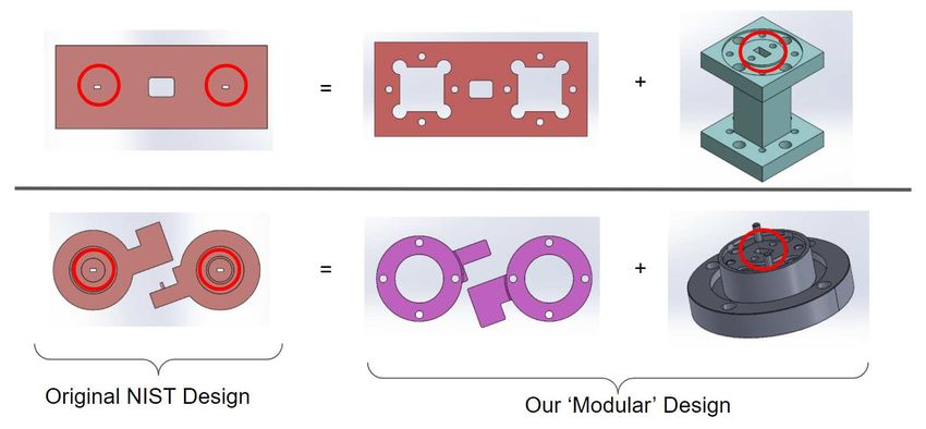
Assembly
Three important aspects of the physical                    This wrench will fold in once the appropriate
calorimeter are that it can be easily                      torque is applied.
assembled, easily replicated, and robust.
Since the entire microwave calorimeter is only             Another assembly consideration is the usage
about 3 inches wide and 4 inches tall while                of a granite inspection slab as a flat surface in
consisting of 135 components, assembly was                 order to gently align components. Custom and
sure to be challenging. To ease the assembly               commercial parts are held together with
process, we made sure that all screw lengths               screws, guide pins, and thermal paste which
would be easily identifiable and share                     all provide precise alignment in the horizontal
consistently sized hex sockets. In order to                directions. Additionally, the inspection slab
reduce the risk of applying too much torque on             provides less than 1 thousandth of an inch of
the screws, a specialized break-over torque                tolerance in the vertical direction, reducing the
wrench fastens all screws.                                 possibility of misalignment and a poor fit.

           A flat lay of our microcalorimeter components with a quarter (bottom-left) for scale. Some of
            these parts had not arrived at the time this photo was taken. The bulkhead adapters and
            waveguides are substituted for their 3D printed versions and the isolation sections shown
             have not been gold-plated. Our timeline was shifted because of the first semester spent
                                                 thermal modeling.
                                                                                                               8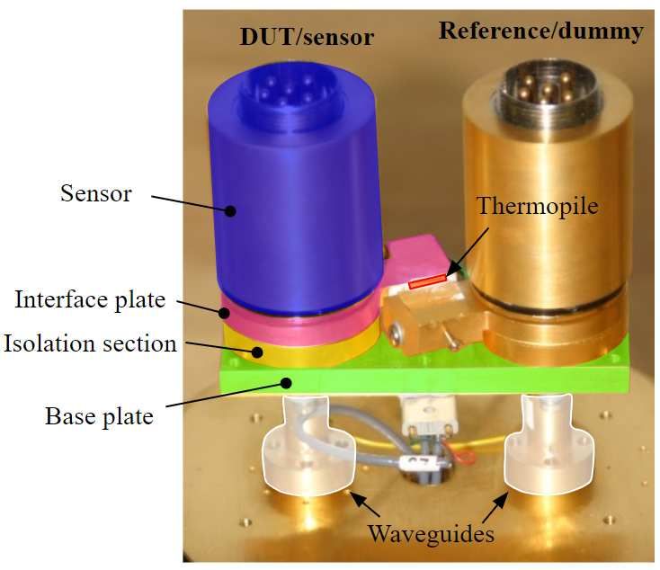
Conclusion

Overall, this project was a great success. Our           One of the design challenges of our project
thermal simulations allowed us to determine the          was our $2,000 department budget. Therefore,
correction coefficient of NIST's previous                we strived to maximize the number of
microcalorimeter design. Additionally, these             commercial parts and minimize custom
simulations served as a convenient and accurate          manufacturing since the microcalorimeter's
way for NIST and future senior design teams to           high precision tolerances would have
continue testing the theoretical heat distributions in   exponentially raised the total cost of the project
their calorimeter designs. Our clients have also         had we sourced more custom components. By
received our improved physical microcalorimeter          carefully redesigning certain custom parts, we
to be used for testing, and a parts brochure in          were able to refine the calorimeter assembly
case they want to order new parts. Future senior         and utilize commercial part interfacing, aiming
design teams who continue this project will have         to reduce error in part-to-part mating.
the opportunity to test our physical calorimeter
and compare the experimental correction                  Our clients estimated that the original
coefficient to the one from our thermal simulations.     calorimeter with its many custom components
They can also alter our simulations to reflect the       would have cost upward of $50,000 to
new design.                                              manufacture. With our new calorimeter design,
                                                         using off-the-shelf components and only a
                                                         couple of custom parts, the total cost with
                                                         additional replacement parts came out to
                                                         $7,500. This new design is not only cheaper
                                                         than the original, but has advantages over the
                                                         initial design. Our calorimeter is more modular
                                                         than the original design; therefore, if one piece
                                                         wears out over time, it can be re-ordered from
                                                         an established supplier of microwave
                                                         components instead of remanufactured. While
                                                         we didn't have time to test the physical
                                                         calorimeter since we used the first semester to
                                                         create the thermal simulation, we expect this
                                                         will allow for increased longevity and better
                                                         connection repeatability over time. This is
                                                         ultimately our clients' goal for the new design
                                                         as they believe a major source of the error in
                                                         their experiments is lack of connection
                                                         repeatability due to wear.

                                                                                                              9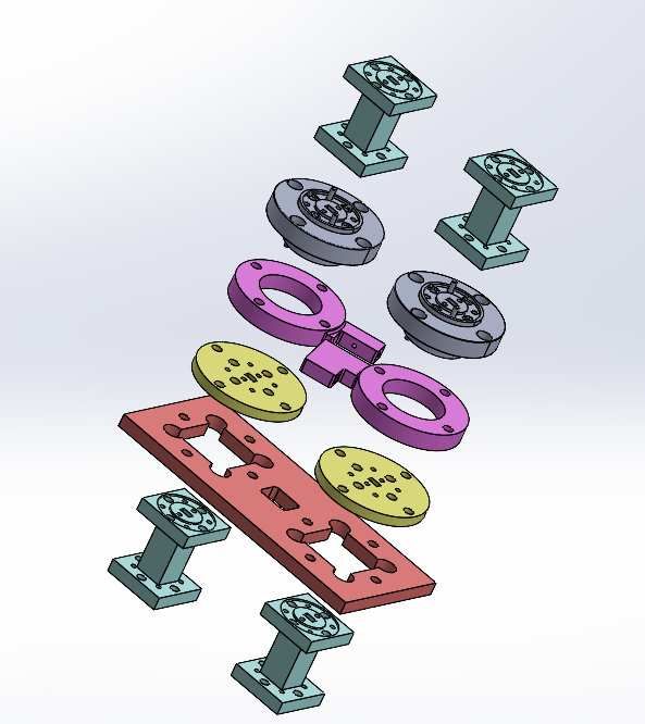
Meet the Team
       Ryan Brink is the team’s Project         Megan Borfitz is the team's logistics
       Manager, and will receive his BS in      manager whose responsibilities
       Mechanical Engineering this spring,      included documentation,
       and MS the following year. He is         communication, and planning. She will
       currently in the final stages of the     be graduating with a BS in mechanical
       NUPOC program application process        engineering and a minor in computer
       where after college he will be a         science. She looks forward to using
       nuclear engineer with the US Navy.       her skills to contribute to sustainability.

       Paul DiTomas is the test engineer for     Chase is the team’s Systems
       the team, whose main responsibilities     Engineer, and will graduate with a
       included analyzing the simulation         BS in Mechanical Engineering.
       results and applying them to the new      Afterwards he will be pursuing a job
       design. He is graduating with a BS in     as a professional engineer at a
       mechanical engineering and a minor        defense and aerospace company
       in music, and is looking forward to       and will continue his pursuit of
       career opportunities in research,         design challenges and problem
       management and design.                    solving.

       Paris Buedel is the team’s CAD             Sophia Henze is the team's
       Engineer, and will graduate with a BS      Financial Manager, and will
       in Mechanical Engineering and              graduate with a BS in Engineering
       minors in Energy Engineering,              Plus with an emphasis in
       Leadership Studies, and Chinese.           mechanical engineering and a
       Paris will continue to study thermal       concentration in Creative Design
       design as a mechanical engineer at         and Technology. She has accepted
       the Laboratory for Atmospheric and         a position at Deloitte Consulting and
       Space Physics.                             is looking forward to continuing
                                                  combining her passions of
                                                  engineering and design.

        Austin Hegemann is the team’s
        Manufacturing Engineer, and will           Dr. Longji Cui is an Assistant
        receive his BS this coming spring          Professor in the Department of
        and MS the following spring of 2022,       Mechanical Engineering and acted
        both in Mechanical Engineering.            as the Director for this project. His
        Austin is looking forward to pursuing      lab focuses on experimental and
        his passion of design and                  theoretical research of micro and
        manufacturing for his professional         nanoscale heat transport and energy
        career.                                    conversion. His experience assisted
                                                   the team greatly with the micro-scale
                                                   and theoretical nature of the project.

                                                                                      10
You can also read