Nonlinear Vibrations of Innovative One-Way Clutch in Vehicle Alternator - MDPI

Page created by Christian Guerrero
 
CONTINUE READING
Nonlinear Vibrations of Innovative One-Way Clutch in Vehicle Alternator - MDPI
inventions
Article
Nonlinear Vibrations of Innovative One-Way Clutch
in Vehicle Alternator
Xiaotian Xu 1     ID
                       , Gang Chen 1, *, Joshua Colley 1 , Pengrui Li 1 and Mohamad Qatu 2
 1   College of IT & Engineering, Marshall University, Huntington, WV 25755, USA; xu33@marshall.edu (X.X.);
     cooley_2007@hotmail.com (J.C.); li75@live.marshall.edu (P.L.)
 2   College of Technology, Eastern Michigan University, Ypsilanti, MI 48197, USA; mqatu@emich.edu
 *   Correspondence: chenga@marshall.edu; Tel.: +1-304-634-8138
                                                                                                   
 Received: 27 May 2018; Accepted: 26 July 2018; Published: 30 July 2018                            

 Abstract: One-way clutches have been proposed for vehicle alternators. The clutch can play an
 important role in reducing vibrations of the vehicle engine accessory system, but the severe vibrations
 of the clutch subsystem limit its stability and durability. This paper investigates the nonlinear
 vibrations of a one-way clutch between the accessory pulley and the alternator shaft. The one-way
 clutch is modelled as a discontinuous stiffness system, and the simplified model is analyzed using
 discontinuous transform to determine the periodic, primary resonance and the sub and super
 harmonic resonance solutions. The typical system model is numerically solved and the spectrum
 and phase plots are characterized. The results give a big picture of and insights into the nonlinear
 vibration features of one-way clutch system. A relevant US patent is pending.

 Keywords: vehicle alternator; engine system; front-end accessory; belt-pulley system; one-way
 clutch; nonlinear dynamics

1. Introduction
     Vehicle engine front-end accessory drive systems are widely used in passenger vehicles and
heavy-duty trucks. Using a single belt, engine power is delivered from the crankshaft to a variety
of accessories such as the air conditioner, alternator, power steering, water pump among others.
Crankshaft torque pulsations from the cylinder combustion in the engine, and dynamic accessory
torques could excite severe rotational vibrations of the subsystems [1–3]. The periodic firing of the
engine cylinders causes the crankshaft to have periodic motion superimposed on a steady angular
velocity. This periodic motion is transferred to various engine accessories. As the engine speed
increases, the frequency of crankshaft pulses increases, causing belt tension drop and belt slip on
the pulley. The alternator, with its very large moment of inertia, is most susceptible to dynamic
tension fluctuations; hence, there is a need to find ways to reduce the steady-state peak tension
drop across it. To address the issues of vibration, one-way clutch pulleys have been developed and
used in vehicle alternators [4–9]. With the aim of detaching the alternator from the rest accessory
subsystem during high speed transients and to reduce the transmission of torsional vibrations from
the internal combustion engine to the engine accessories, one-way clutches have been used more and
more frequently to decouple the alternator system and reduce the system’s vibrations. The one-way
clutches with wrap springs have been introduced into the generator to allow the high inertia element
to overrun the system when the pulley is decelerating.
     To avoid the impact generated during system engagements, the wrap spring one-way clutch, also
called over-running alternator de-coupler (OAD), as shown in Figure 1 was used. It has a torsional
wrap spring-damper that connects the pulley to the outer ring of the clutch [4–8]. In wrap-spring

Inventions 2018, 3, 53; doi:10.3390/inventions3030053                       www.mdpi.com/journal/inventions
Nonlinear Vibrations of Innovative One-Way Clutch in Vehicle Alternator - MDPI
Inventions 2018, 3,
Inventions 2018, 3, 53
                    x FOR PEER REVIEW                                                                  22 of
                                                                                                          of 10
                                                                                                             10

spring clutches, a helical spring, typically wound with square-cross-section wire, is used. The torsion
clutches, a helical spring, typically wound with square-cross-section wire, is used. The torsion spring
spring also acts as a dampening mechanism which greatly reduces the belt vibration.
also acts as a dampening mechanism which greatly reduces the belt vibration.

                                                                             pulley.
                            Figure 1. Schematic of one-way clutch alternator pulley.

      The application of the one-way clutch has a strong influence on the entire system’s dynamic
      The application of the one-way clutch has a strong influence on the entire system’s dynamic
behavior. Under certain circumstances, the unique features of the one-way clutch allow the belt spans
to experience large transverse vibrations or the clutch to have larger torsional vibrations. There are
many research studies dedicated to the vibration analysis of a one-way clutch. To accurately predict
the entire system’s dynamic behavior, the motions of the one-way clutch need to be considered in the
the entire system’s dynamic behavior, the motions of the one-way clutch need to be considered in
models. This results in a strong nonlinear system due to the special stiffness discontinuous property
the models. This results in a strong nonlinear system due to the special stiffness discontinuous
of the one-way clutch. Balaji and Mockensturm established a mathematical model of accessory
property of the one-way clutch. Balaji and Mockensturm established a mathematical model of
system with seven pulleys with a one-way clutch, and the piece-wise linear system is numerically
accessory system with seven pulleys with a one-way clutch, and the piece-wise linear system is
solved for specific cases using the Runge-Kutta method [10]. Ding and Zu solved a similar model
numerically solved for specific cases using the Runge-Kutta method [10]. Ding and Zu solved a
numerically and used fast Fourier transform to derive the natural frequency of the nonlinear
similar model numerically and used fast Fourier transform to derive the natural frequency of the
vibration [11]. For the similar model, Ding and Hu used two different approaches: (a) The nontrivial
nonlinear vibration [11]. For the similar model, Ding and Hu used two different approaches: (a) The
solutions of viscoelastic model; and (b) the iterative solution, to determine the nontrivial equilibriums
nontrivial solutions of viscoelastic model; and (b) the iterative solution, to determine the nontrivial
of dynamical system numerically. They also studied the natural frequencies of the system by using
equilibriums of dynamical system numerically. They also studied the natural frequencies of the system
the Galerkin method [12]. Zhu and Parker established a model of the accessory system with two
by using the Galerkin method [12]. Zhu and Parker established a model of the accessory system
pulleys having a one-way clutch, and the dynamical system was analyzed by using the harmonic
with two pulleys having a one-way clutch, and the dynamical system was analyzed by using the
balance method, with the dynamical properties characterized in terms of spring stiffness, excitation
harmonic balance method, with the dynamical properties characterized in terms of spring stiffness,
amplitude, and moment inertia of pulleys [13]. Zeng and Shangguan established a model of the
excitation amplitude, and moment inertia of pulleys [13]. Zeng and Shangguan established a model
accessory system, with three pulleys having a one-way clutch, which consists of a driving pulley, a
of the accessory system, with three pulleys having a one-way clutch, which consists of a driving
driven pulley and a tensioner. The dynamical system is analyzed numerically by using the Gear
pulley, a driven pulley and a tensioner. The dynamical system is analyzed numerically by using the
method, with the dynamical properties being characterized and optimized in terms of clutch spring
Gear method, with the dynamical properties being characterized and optimized in terms of clutch
stiffness, excitation amplitude and moment inertia of pulleys [14]. In-vehicle experimental tests are a
spring stiffness, excitation amplitude and moment inertia of pulleys [14]. In-vehicle experimental tests
significant way to investigate the vibrations of alternator pulleys. An experimental procedure,
are a significant way to investigate the vibrations of alternator pulleys. An experimental procedure,
including proper selection of parameters, measures and sensors, to evaluate the potential vibrations
including proper selection of parameters, measures and sensors, to evaluate the potential vibrations of
of each alternator pulley is proposed by Michelotti, Pastorelli et al. [15]. The existing research
each alternator pulley is proposed by Michelotti, Pastorelli et al. [15]. The existing research characterizes
characterizes many linear and nonlinear vibration properties of one-way clutch for many specific
many linear and nonlinear vibration properties of one-way clutch for many specific cases. There has
cases. There has been a lack of overall understanding of global characteristics of the strong nonlinear
been a lack of overall understanding of global characteristics of the strong nonlinear vibrations of
vibrations of one-way clutch system. For practicing accessory drive designers in the
one-way clutch system. For practicing accessory drive designers in the automotive/heavy vehicle
automotive/heavy vehicle industries, the natural frequencies and dynamic response are of utmost
industries, the natural frequencies and dynamic response are of utmost interest. Predicting the system’s
interest. Predicting the system’s dynamic behavior in the design stage is important because the
dynamic behavior in the design stage is important because the changes are difficult to accomplish once
changes are difficult to accomplish once prototypes are built. This requires a comprehensive model
of the one-way clutch to characterize the system’s properties, particularly all kinds of resonances. In
Nonlinear Vibrations of Innovative One-Way Clutch in Vehicle Alternator - MDPI
Inventions 2018, 3, 53                                                                                                             3 of 10

 prototypes
Inventions 2018,are
                 3, x built. ThisREVIEW
                      FOR PEER    requires       a comprehensive model of the one-way clutch to characterize                        3 ofthe
                                                                                                                                         10
 system’s properties, particularly all kinds of resonances. In this paper, the functional principles of the
this paper,clutch
 one-way        the functional       principlesinvestigated
                        will be theoretically         of the one-way            clutch will
                                                                        and explained           be theoretically
                                                                                             while                   investigated
                                                                                                     the comprehensive                and
                                                                                                                              resonances
explained
 features willwhile      the comprehensive
                   be reported.      The analytical   resonances         features
                                                           results clearly        show willthat
                                                                                             be there
                                                                                                  reported.
                                                                                                        exist The   analytical
                                                                                                               primary,           results
                                                                                                                           subharmonic,
clearly  show that there
 and superharmonic               exist primary,
                             resonances.               subharmonic,
                                            The numerical           analysis and    superharmonic
                                                                                 illustrated             resonances.
                                                                                                the detailed             Thestudy
                                                                                                               cases. This    numerical
                                                                                                                                     offers
analysis
 some insights for the product design into how to pinpoint and avoid varied resonance cases. how
           illustrated     the  detailed   cases.    This   study     offers    some    insights   for the  product    design   into
to pinpoint and avoid varied resonance cases.
 2. Mathematical Model
2. Mathematical Model
       Based on the real system of the wrap-spring one-way clutch [4–13], the model is given as follows.
 When    the rotations
      Based   on the real   ofsystem
                               the wrap-spring          ends, for one-way
                                        of the wrap-spring            which theclutch pulley[4–13],
                                                                                               rotation
                                                                                                      theexceeds
                                                                                                          model isthe     accessory
                                                                                                                      given           shaft
                                                                                                                              as follows.
 rotation,
When    the then     the clutch
             rotations             is engaged. Power
                           of the wrap-spring          ends, for transmission
                                                                     which the pulley takes place    from
                                                                                              rotation      the driving
                                                                                                         exceeds            to the driven
                                                                                                                   the accessory     shaft
 pulley. For
rotation,   then thethealternate
                          clutch iscase   where Power
                                     engaged.        accessory       rotation istakes
                                                               transmission           less than
                                                                                            placepulley    rotation,
                                                                                                    from the    drivingthetowrap-spring
                                                                                                                              the driven
 diameter
pulley.   Fordecreases
               the alternateand the
                                  caseclutch
                                         wheredisengages;
                                                    accessoryno       torque is transmitted.
                                                                    rotation         less than pulleyA theoretical
                                                                                                          rotation, model     of one-way
                                                                                                                      the wrap-spring
 clutch   on  a   two-pulley      system    is shown        in  Figure      2.  The    driving    pulley
diameter decreases and the clutch disengages; no torque is transmitted. A theoretical model of one-        represents     the crankshaft,
 and clutch
way   its motion       is specifiedsystem
               on a two-pulley        as harmonic
                                                is shown  oscillation.
                                                               in FigureIn   2. vehicle
                                                                                 The drivingapplications,    engine firing
                                                                                                  pulley represents            pulsations
                                                                                                                         the crankshaft,
 induce
and        periodic
     its motion       is fluctuations     in crankshaft
                         specified as harmonic                   speed at
                                                         oscillation.      In the     firing
                                                                                vehicle       frequency. engine
                                                                                           applications,      The driven
                                                                                                                      firing pulley    was
                                                                                                                              pulsations
 connected
induce         to thefluctuations
          periodic        accessory. The     one-way clutch
                                         in crankshaft          speedis at integrated
                                                                               the firingbetween       the accessory
                                                                                              frequency.     The driven   pulley  andwas
                                                                                                                             pulley     the
 alternator to
connected     shaft.
                   the The    mathematical
                         accessory.              modelclutch
                                       The one-way           of the system        is given
                                                                      is integrated          by the the
                                                                                          between     following    equations:
                                                                                                           accessory    pulley and the
alternator shaft. The mathematical   ( .. model         . of the system is given         by the following equations:
                                         J+θ
                                          p p  +    c +θ
                                                      p p  +   k p+ p
                                                                   θ  +   g −p
                                                                             θ    −  θ =
                                                                                       a = M cos ωt
                                                  ..         .                                                                           (1)
                                                                                                                                        (1)
                                               +
                                               Ja θ a + c+a θ a + k+  a θa + g −   θa − θ =    0 0
                                                                                            
                                                                                           p =

in which:         and      are the vibration angle of driven pulley and alternator shaft, respectively;
 in which: θ p and θ a are the vibration angle of driven pulley and alternator shaft, respectively; J p and
and       are  the  moment
 Ja are the moment of inertiaof inertia   of driven
                                     of driven        pulley
                                                  pulley  andand   alternator
                                                                alternator         shaft,
                                                                               shaft,     respectively;
                                                                                      respectively;   c p cand
                                                                                                            p and
                                                                                                                kp k  p are
                                                                                                                     are the
the  damping     and  stiffness constants   associated   with  driven     pulley,  respectively;      =
 damping and stiffness constants associated with driven pulley, respectively; k p = 2Kb r p , and c a and 2   2   , and
and        aredamping
 k a are the    the damping    and stiffness
                         and stiffness         constants
                                        constants          associated
                                                     associated  with the with   the of
                                                                              rotor  rotor  of alternator,
                                                                                        alternator,          respectively.
                                                                                                    respectively.    M and
Mω are respectively the amplitude and frequency of excitation acted on driven pulley due to due
     and   ω  are  respectively  the amplitude      and frequency      of excitation    acted on  driven   pulley         to
                                                                                                                     engine
engine    firing excitation.
 firing excitation.           The torque
                       The torque           transmitted
                                   transmitted      betweenbetween     the accessory
                                                              the accessory       pulleypulley   and alternator
                                                                                          and alternator            shaft
                                                                                                             shaft is     is
                                                                                                                      given
given   as
 as follows,follows,
                                                      (                
                                                            θ p − θ, a , >
                                                          kd −               θ p > θa
                                      g θ−p − θ a = =                                                                     (2)
                                                                                                                         (2)
                                                       0, 0,               >θ p > θ a

                                          Theoreticalmodel
                               Figure2.2.Theoretical
                              Figure                 modelof
                                                           ofone-way
                                                              one-wayclutch
                                                                      clutchin
                                                                             inaccessory
                                                                                accessorysystem.
                                                                                          system.

      The
       Theequation
           equationdescribed
                       describedby byEquation
                                      Equation(1) (1)has
                                                      hasbeen
                                                         beenstudied
                                                               studiednumerically
                                                                       numericallyandandtheoretically
                                                                                          theoreticallyunder
                                                                                                        under
particular
particularconditions
            conditions[13].
                         [13].
      Generally,
       Generally, Equation
                  Equation (1)
                             (1) represents
                                 represents aa strong
                                               strong nonlinear
                                                       nonlinear system.
                                                                  system. Consider
                                                                          Considerthe
                                                                                    thesimplest  case,θ p ≥ ≥
                                                                                        simplestcase,       θa ;
   ; the system  is linear and  the squares  of  the natural frequencies  are derived
 the system is linear and the squares of the natural frequencies are derived as       as

                          ,   =(      +      )/2 ∓              +           −4              −               /2                        (3)
Nonlinear Vibrations of Innovative One-Way Clutch in Vehicle Alternator - MDPI
Inventions 2018, 3, 53                                                                                      4 of 10

                                                 v
                                                               2                         !
                               k011
                                                 u  0                0 0
                    2                 k022       u  k11   k022        k11 k22   k012 k021
                   ω21,22   =(      +      )/2 ∓ t      +         −4          −              /2                (3)
                                Jp     Ja            Jp    Ja          J p Ja     J p Ja

in which k011 = k p + k d , k012 = k d = k021 and k022 = k a + k d . Furthermore, letting k d = 0,
which deteriorates to the natural frequencies of two independent systems: The accessory system
and the uncoupled alternator. For the case with both θ p ≥ θ a and θ p ≤ θ a , the system exhibits a
nonlinear feature.
    Consider the case in which the driven pulley mode and alternator shaft mode motion can be
decoupled, and we just discuss driven pulley mode, then Equation (1) can be approximated by
                                    ..        .                            
                                J p θ p + c p θ p + k p θ p + k d θ p − θ a = M cos ωt,   θ p ≥ θa
                                  ..       .                                                                   (4)
                                J p θ p + c p θ p + k p θ p = M cos ωt,                   θ p ≤ θa

     By using the approach given in References [16,17], a comprehensive analytical solution is
systematically derived through the discontinuous transformation, and the results are given in
next section.

3. Theoretical Analysis
     Closed form analytical solutions are of great significance in configuring the overall vibration
characteristics. The problem described by Equation (4) is identical to the harmonic force excited
by the unsymmetrical piecewise-linear spring-damping system. Because the non-linearities in this
problem cannot be assumed to be small, a general analytical solution, by only using conventional
methods such as the perturbation method, is not feasible. By using the discontinuous transformation
method [16,17], a far-from resonance solution, nearly a primary resonance solution, a super-harmonic
resonance solution and a sub-harmonic resonance solution are systematically derived as follows:

3.1. Free Vibration (under Unit Initial Condition)

                                                       1 ∞ sin nα0 cos(ω1 + nω0 )t + cos(ω1 − nω0 )t
                                    
                ω0                ω
        θp =       cos ω1 t + 1 − 0 cos(ω2 t − β 0 ) +    ∑
               2ω1               2ω1                   π n =1                 n
                                                                                                               (5)
                                ω1 ∞ sin nα0 cos[(ω1 + nω0 )t + β 0 ] + cos[(ω2 − nω0 )t + β 0 ]
                            −        ∑
                                πω2 n=1                         n

                         p                      q
in which ω1 =                k p /J p , ω2 =         (k p + k d )/J p , ω0 = 2ω1 ω2 /(ω1 + ω2 ), α0 = πω0 /(2ω1 ),
β 0 = π (1 − ω2 /ω1 )/2.

3.2. Far-From Resonance Solutions

                               M ω22 − ω12                M ω12 + ω22 − 2ω 2
                                                                            
                   θp =                           +                            sin ωt
                        π J p ω12 − ω 2 ω22 − ω 2     2J p ω12 − ω 2 ω22 − ω 2
                                                                   

                                           2F ω22 − ω12         ∞
                                                        
                                                                       cos 2nωt
                                  +         2
                                                    2         ∑
                                    π J p ω1 − ω ω2 − ω n=1 (2n + 1)(2n − 1)
                                                 2          2

                                        1                                                                      (6)
                                       + [ A1 sin ω1 t + A2 sin(ω2 t + β 0 )]
                                        2
                                        A     ∞    cos(ω1 − nω )t − cos(ω1 + nω )t
                                       + 1 ∑
                                         π n=1,3,5                  n
                                                 ∞
                                       cos[(ω2 − nω )t + β 0 ] − cos[(ω1 + nω )t + β 0 ]
                                           A2
                                       −        ∑
                               n=1,3,5     π                   n

in which β 0 = −πω2 /ω, A1 = Mω/ J p ω1 ω 2 − ω12 , A2 = −Mω/ J p ω2 ω 2 − ω22 .
                                                                               
Nonlinear Vibrations of Innovative One-Way Clutch in Vehicle Alternator - MDPI
Inventions 2018, 3, 53                                                                                                       5 of 10

3.3. Near-Primary Resonance Solutions

                      "                                                #
                                      2M                    3M                            π Jp
              θp =                                  +                    sin ωt −                   cos ωt
                         (ω22 − ω12 ) J p (2∆ + 1) 4ω 2 J p (2∆ + 1)2             2ω 2 J p (2∆ + 1)
                                                   M          ∞     cos(n − 1)ωt − cos(n + 1)ωt
                                         +      2             ∑                                                                 (7)
                                            πω J p (2∆ + 1) n=1,3,5
           Inventions 2018, 3, x FOR PEER REVIEW
                                                                                  n                     5 of 10
                                M (ωt − π )     ∞    sin(n − 1)ωt + sin(n + 1)ωt
                                    − Solutions
           3.3. Near-Primary Resonance    2     ∑
                             πω J p (2∆ + 1) n=1,3,5              n
                         2                  3
                =2 / ω 2 − ω 2 .
where ∆ = ω12 − ω                   +                sin  −              cos
                             
                            1 + 1) 4
                  ( − 2 ) (2∆              (2∆ + 1)         2   (2∆ + 1)
                                                                   cos( − 1)    − cos( + 1)
3.4. Super-Harmonic Resonance +Solutions
                                      (2∆ + 1)                                                                       (7)
                                                             , ,
                                            ( − )            sin( − 1) + sin( + 1) 
                         M 2n2 ω 2 −− ω 2 −(2∆ ω12+ 1)                    2M (ω22 − ω12
                  θp =                    2
                                                     sin  , , +
                                                         ωt                    2
                                                                                                 cos ωt
                                                                 π J p (n2 − 1) ω12 − n2 ω 2 ω 2
                                                                                            
           where ∆= ( − J p)/( (n2 −−1) ).ω 4
                                                                                                                                (8)
                                             2M (ω22 − ω12
                                                               
                                −
           3.4. Super-Harmonic Resonance  Solutions2                      cos nωt, n = 2, 3, 4, · · ·
                                   π J p (n2 − 1) ω12 − n2 ω 2 ω 2
                                                                    
                               (2
                                −    − )               2 (( − )
                          =                sin  +                      cos
                           (   −  1)                ( − 1) ( −      )
3.5. Sub-Harmonic Resonance Solutions                                                       (8)
                                         2 (( − )
                                 −                         cos  ,     = 2, 3, 4, ⋯
      For the case of ω2  ω1 , it can(be − 1) ( −out that
                                          derived       ) the approximate solution in the proximity of
sub-harmonic resonant frequency is:
           3.5. Sub-Harmonic Resonance Solutions
                                                                           (n −solution
                                                                                               
               For the case of   ≫ , it can be derived out
                                                        (n+that
                                                            1)ωtthe approximate
                                                               h          i      1)ωt in the proximity of
                                                   cos             − cos
                           4l M frequency is: ∞
           sub-harmonic resonant                            l                   l
         θp =
                π 2 J p ω1 (l 2 − 1)(ω − lω1 )      ∑       ( + 1)              n( − 1)
                                                                                                    ,   l = 2, 4, 6, · · ·      (9)
                                4                    cos
                                                  n=1,3,5               − cos
                  =                                                                       ,     = 2, 4, 6, ⋯         (9)
                              ( − 1)( −       )
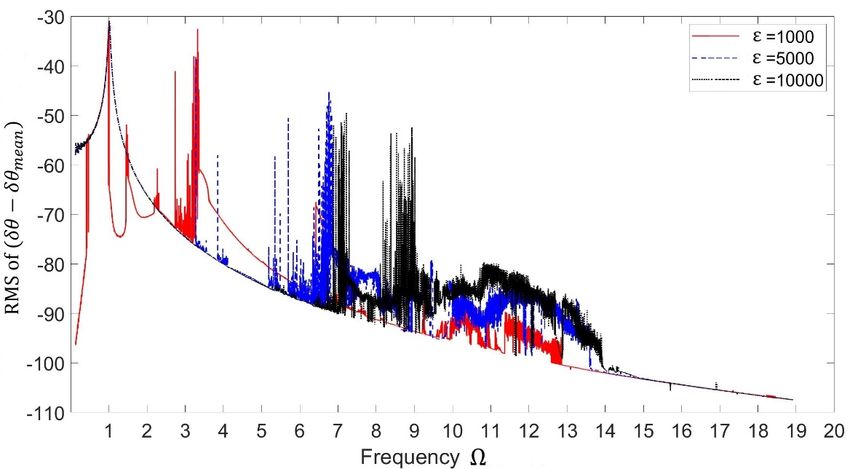
     Figure 3 illustrates a typical result of the response amplitude as a function of the excitation
                                                   , ,

frequency ration.
              FigureThe      curve in
                        3 illustrates     Figureresult
                                      a typical     3 exhibits   a series amplitude
                                                         of the response    of resonantas apeaks   including
                                                                                            function           the 1/2th and
                                                                                                     of the excitation
         frequency
1/3th order           ration. The curve
               superharmonic                in Figure 2nd
                                      resonance,      3 exhibits
                                                            and a3rdseries of resonant
                                                                        order          peaks including
                                                                                subharmonic             the 1/2th
                                                                                                  resonance    as and
                                                                                                                   well as the
primary resonance. It is noted that in existing research, certain experiments [9,15,18] were the
         1/3th   order  superharmonic       resonance,  2nd  and  3rd  order  subharmonic    resonance as well  as  conducted
         primary resonance. It is noted that in existing research, certain experiments [9,15,18] were conducted
and compared      with   preceding     linear    vibration  theory    of a one-way    spring   clutch.
         and compared with preceding linear vibration theory of a one-way spring clutch. This paper
                                                                                                       This  paper   proposed
an advanced     nonlinear
         proposed              vibration
                     an advanced              theory
                                      nonlinear       of thetheory
                                                  vibration   one-wayof theclutch  which
                                                                             one-way  clutchencompasses      the linear
                                                                                              which encompasses    the cases,
and as such,
         linearitcases,
                  is consistent    with
                        and as such,   it isall existing
                                             consistent   experimental
                                                        with                results. results.
                                                             all existing experimental

                                    Figure 3. The frequency response function (   k=d 4, = 0.05).
                              Figure 3. The frequency response function (             = 4, ξ = 0.05).
                                                                                  kp
Nonlinear Vibrations of Innovative One-Way Clutch in Vehicle Alternator - MDPI
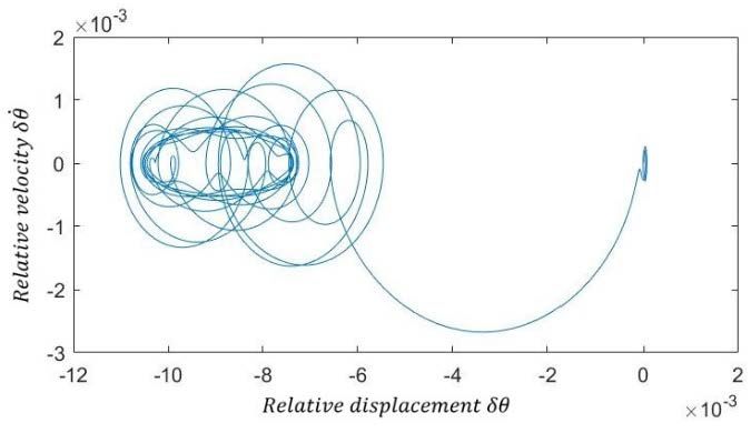
Inventions 2018, 3, 53                                                                                             6 of 10

4. Numerical Analysis
      In this section, the numerical analysis of a typical one-way clutch system, characterized by
Equation     (1), 2018,
        Inventions  is presented.       Table 1 shows the parameters for the typical system. The6 frequency,
                         3, x FOR PEER REVIEW                                                                   of 10
ω0 , is considered as the natural frequency for the linear single            q  degree   of  freedom    system   when the
        4. Numerical Analysis                                                                  
accessory is not equipped with one-way clutch, and ω0 = k p / J p + Ja . Corresponding to the
case of theIn      this section,
               linear    system the    numerical
                                   which          analysis in
                                           is mentioned    of Section
                                                              a typical2,one-way  clutch system,natural
                                                                          the dimensionless        characterized  by
                                                                                                          frequencies are
Ω1 = ω  Equation
            /ω      =(1), is presented.
                       0.987    and  Ω   Table
                                         =  ω  1/ω
                                                 shows
                                                     = the
                                                       6.931parameters
                                                               for the for the typical
                                                                       values   in     system.
                                                                                   Table  1.     The frequency,
                                                                                              These   two           ,
                                                                                                           dimensionless
          1     0                      2      2    0
        is considered as the natural frequency for the linear single degree of freedom system when the
natural frequencies could be the criterion to evaluate how the system works under different conditions.
       accessory is not equipped with one-way clutch, and           =      /( + ). Corresponding to the case
       of the linear system which is mentioned    in Section 2,for
                                       Table 1. Parameters      thetypical cases. natural frequencies are Ω =
                                                                    dimensionless
          ⁄ = 0.987 and Ω = ⁄ = 6.931 for the values in Table 1. These two dimensionless natural
       frequencies could be the criterion to evaluate how the system works under different conditions.
                                Radius of Driven Pulley                      0.0286 (m)
                                  Radius of crankshaft                          0.04 m
                                         Table 1. Parameters for typical cases.
                            Driven Pulley Moment of Inertia                0.0016 (kgm2 )
                             Alternator
                                    RadiusMoment     of Inertia
                                             of Driven   Pulley            0.0050(m)
                                                                          0.0286    (kgm2 )
                                  Modal   damping
                                      Radius          ratio
                                               of crankshaft                0.04 m5%
                               DrivenBelt   stiffness
                                        Pulley  Moment of Inertia            250(kgm
                                                                        0.0016     kN/m
                                                                                      2)

                                 Clutch  spring
                                 Alternator       stiffness
                                              Moment    of Inertia       50–1500
                                                                        0.0050      Nm/rad
                                                                                 (kgm 2)

                                  Excitation  amplitude
                                      Modal damping      ratio                0.001
                                                                              5% rad
                                         Preload
                                          Belt stiffness                        2.3 Nm
                                                                          250 kN/m
                                     Clutch spring stiffness          50–1500 Nm/rad
                                      Excitation   amplitude
      To conduct the numerical analysis of the dynamic model               0.001with
                                                                                  rad the above parameters using
                                             Preload                        2.3 Nm
MATLAB, the discontinuous stiffness nonlinearity which was indicated by Equation (2) can be
efficiently approximated as a continuous function. A smoothed function is used to approximate
            To conduct the numerical analysis of the dynamic
                                                             model with the above parameters using
the discontinuous
       MATLAB, thestiffness  nonlinearity
                     discontinuous            θ p − θ a . which was indicated by Equation (2) can be
                                   stiffnessgnonlinearity
        efficiently approximated as a continuous function. A smoothed function is used to approximate the
                                                   1
                                         g(δθ () =− K).[1 + tanh(εδθ )]δθ
        discontinuous stiffness nonlinearity
                                                          d                                                          (10)
                                                      2
                                                 1
                                         ( )=         [1 + tanh(    )]                                         (10)
in which δθ = θ p − θ a , and the ε is the 2smooth constant which is usually a large positive number,
       in whichε = =
for instance,              − [13].
                      10, 000  , and The
                                      the clutch   torque constant
                                            is the smooth    is approximated     by a hyperbolic
                                                                     which is usually                 tangent
                                                                                        a large positive         function
                                                                                                           number,
as shown    in Figure=4.10,000
       for instance,         What[13].
                                    weThe   clutch
                                         want   thetorque  is approximated
                                                     approximated            by a hyperbolic
                                                                       function    to be is atangent    function function,
                                                                                               proportional      as
       shown   in Figure  4. What  we  want  the approximated    function to be is a proportional
with the slope being Kd when δθ ≥ 0 and being 0 when δθ ≤ 0. As shown by the results in Figure 4,   function, with
       the slope being       when      ≥ 0 and being 0 when        ≤ 0. As shown by the results in Figure 4, the
the approximation is obviously not accurate when ε = 10 because the curve deviates from the desired
       approximation is obviously not accurate when = 10 because the curve deviates from the desired
trajectory,  and the satisfied approximation is likely to be obtained for large ε > 100. This is because
       trajectory, and the satisfied approximation is likely to be obtained for large > 100. This is because
the results   of ε =
       the results of 100  andand
                        = 100    ε = 10,  000 look
                                       = 10,000  looktotohave
                                                          have overlapped     each
                                                                overlapped each      other
                                                                                  other      in figure.
                                                                                        in the  the figure.    The actual
                                                                                                         The actual
effectseffects
        of different   values  of   will be  further   investigated   when   conducting     the  frequency
               of different values of will be further investigated when conducting the frequency analysis
                                  ε                                                                           analysis by
       by  employing   these
employing these values below.values below.

                       Figure
                   Figure     4. The
                          4. The     clutch
                                  clutch    torque(smooth
                                          torque   (smooth function)
                                                           function) with
                                                                      withdifferent smooth
                                                                            different      constants.
                                                                                      smooth   constants.
Nonlinear Vibrations of Innovative One-Way Clutch in Vehicle Alternator - MDPI
Inventions 2018, 3, 53                                                                                                                   7 of 10
   Inventions 2018, 3, x FOR PEER REVIEW                                                                                               7 of 10
   Inventions 2018, 3, x FOR PEER REVIEW                                                                                               7 of 10
      From  numerical
         From  numerical  investigation,
                            investigation,we
                                           wecan
                                              canestimate
                                                   estimate the
                                                              the effects of
                                                                           of the
                                                                               theapproximations
                                                                                    approximationswith   with  a different
                                                                                                            a different
smooth
   smoothFrom  numerical
          constant,
            constant,ε, for investigation,
                             frequency
                         , for             we can of
                               frequencyanalysis
                                          analysis estimate
                                                   ofthe      the effects
                                                       the system
                                                            system         of thein
                                                                     as shown
                                                                        shown      approximations
                                                                                  in                   with
                                                                                      Figure5.5.InInthis
                                                                                     Figure           this     ΩΩ
                                                                                                            a different
                                                                                                           case,
                                                                                                         case,    is is
                                                                                                                     thethe
   smooth
   ratio
ratio       constant,
         of excitation
      of excitation      , for frequency
                        frequencyand
                     frequency            analysis
                                    andnatural     of the
                                        naturalfrequency
                                                frequencyofsystem
                                                              of the as shown
                                                                  the system.
                                                                      system.    in  Figure 5. In   this case, Ω  is the
   ratio of excitation frequency and natural frequency of the system.

                                  Figure5.5.The
                                 Figure      Thefrequency
                                                 frequency responses
                                                           responses with
                                                                     with different
                                                                          differentvalues
                                                                                    valuesofof ε.
                                                                                               .
                                  Figure 5. The frequency responses with different values of .
            From investigation we found that the approximation is compromised in numerical analysis
       From
    with    From= investigation
                    1000   because we
                      investigation      wefound
                                        the    foundthat
                                             trajectory  is the
                                                       that   the approximation
                                                             not   approximation
                                                                  only   discontinuous  is compromised
                                                                                        is  compromised
                                                                                              and disorderly,     ininbut
                                                                                                                        numerical
                                                                                                                       numerical        analysis
                                                                                                                                      analysis
                                                                                                                            also violate    the
with       =     1000
    natural=frequencies
    withε               because
                    1000 because     the  trajectory
                                        the trajectory
                                  we derived            is
                                                  above.isAnnot  only   discontinuous
                                                             notacceptable
                                                                  only discontinuous
                                                                               approximation  and  disorderly,
                                                                                              and disorderly,
                                                                                                   is attained but      but   also   violate
                                                                                                                            also violate
                                                                                                                      by using              thethe
                                                                                                                                      = 5000.
natural
    natural  frequencies
                  frequencieswe
    The approximation             is derived
                                  we   derived
                                      well       above.
                                                  above. An
                                             accomplished   Anbyacceptable      approximation
                                                                   using =approximation
                                                                acceptable       10,000, the curve isisattained
                                                                                                           attained   byby
                                                                                                           is continuous,        and=εwe
                                                                                                                              using
                                                                                                                           using         5000.
                                                                                                                                         = can
                                                                                                                                             5000.
TheTheapproximation
    clearlyapproximation
                 see the peaks is iswell
                                    ofwellaccomplished
                                                     aroundby
                                            accomplished
                                        resonance              by    and εΩ=
                                                                Ωusing
                                                                   using     =. Thus,
                                                                                 10,000,
                                                                                 10,  000,   the curve
                                                                                            the
                                                                                         a value curve > is  iscontinuous,
                                                                                                                continuous,
                                                                                                           10,000                  and
                                                                                                                                 and
                                                                                                                       is employed     we we
                                                                                                                                           can
                                                                                                                                         when can
clearly
    clearly see    the
                 see    peaks
                      the  peaks  ofofresonance
                                        resonance
    conducting the following numerical analysis.1   around
                                                     around     Ω
                                                                Ω   and
                                                                     and  ΩΩ2 .  Thus,
                                                                                Thus,    aa  value
                                                                                            value    ε >>  10,000
                                                                                                              10, 000  isis employed
                                                                                                                          employed         when
                                                                                                                                         when
    conducting
conducting  In the  thethe following
                         following
                      engine              numerical
                                        numerical
                                front-end               analysis.
                                                      analysis.
                                              accessory   system, the excitation frequency is the engine firing frequency
       In In
    which   the  the  engine
                   engine
                changes     in afront-end
                             front-end
                                  wide range. accessory
                                            accessory     system,
                                                         system,
                                                   The root    mean  the
                                                                    the  excitation
                                                                         excitation
                                                                       square          frequency
                                                                                        frequency
                                                                                 (r.m.s.)  of dynamic isisthe
                                                                                                            the engine
                                                                                                                  enginefiring
                                                                                                              amplitude      firingfrequency
                                                                                                                              of the  frequency
                                                                                                                                       relative
    which       changes
    pulley-accessory
which      changes       inin  a widerange.
                             arotation,
                               wide       range.−The
                                                  Theroot
                                                        root   meanexcitation
                                                           , versus
                                                              mean     square (r.m.s.)
                                                                      square               of
                                                                                            of dynamic
                                                                                    frequency,                amplitude
                                                                                                  for different
                                                                                               dynamic                 values
                                                                                                               amplitude      ofof
                                                                                                                                 the
                                                                                                                                 of    relative
                                                                                                                                     damping
                                                                                                                                    the  relative
    ratios     (   =
    pulley-accessory  3%,  5%    and
                              rotation,8%),     −
                                              are          ,
                                                   calculatedversus
                                                                 and  excitation
                                                                       the results  frequency,
                                                                                      are  shown  for
                                                                                                    in
pulley-accessory rotation, δθ − δθmean , versus excitation frequency, for different values of damping   different
                                                                                                         Figure      6 values
                                                                                                                       for  the  of  damping
                                                                                                                                 parameters
    ratios
    listed
ratios    (ξ in    =
              (= Table
                   3%,3%,5%5%and
                          1.     and8% 8%),   arecalculated
                                          ), are  calculated and and the
                                                                       the results
                                                                           results areare shown
                                                                                           shownininFigure Figure6 6for  forthe
                                                                                                                              theparameters
                                                                                                                                   parameters
    listed    in
listed in Table 1. Table  1.

                                Figure 6. The frequency responses with different damping ratios.
                                Figure6.6.The
                              Figure       Thefrequency
                                               frequencyresponses
                                                         responses with
                                                                   with different
                                                                        different damping
                                                                                  dampingratios.
                                                                                          ratios.
Inventions 2018, 3, x FOR PEER REVIEW                                                                                                                  8 of 10

     The
     The frequency
             frequency responseresponse for     for =   = 8%8% showsshows that that thethe behavior
                                                                                             behavior can  can be  be considered
                                                                                                                       considered as         as linear.
                                                                                                                                                   linear. For
                                                                                                                                                            For
  = 3%    and    5%    ,  non-linear          phenomena            appear.       It   indicates
  = 3% and 5% , non-linear phenomena appear. It indicates that the system is sensitive to the
           Inventions 2018, 3, 53                                                                     that    the    system        is   sensitive
                                                                                                                                               8 of 10 to the
excitation
excitation amplitude.
                amplitude. As       As we  we can can see,
                                                         see, there
                                                                  there are are twotwo resonant
                                                                                           resonant regions
                                                                                                          regions withinwithin the     the two  two natural
                                                                                                                                                        natural
frequencies.
frequencies. The  The    system
                  Thefrequency        is linear
                         system isresponse         when
                                         linear when         the
                                                     for ξ the     clutch
                                                               = clutch
                                                                   8% shows   is engaged.       The
                                                                                   that the behavior
                                                                              is engaged.              non-linearity
                                                                                                           can be considered
                                                                                                The non-linearity            occurs
                                                                                                                             occursas    near
                                                                                                                                         near      the
                                                                                                                                                   the second
                                                                                                                                             linear.     second
resonant     region
           For   ξ =  3% due
                           and  to5%,the   decoupling
                                        non-linear            of
                                                       phenomena   the   clutch
                                                                         appear.    where
                                                                                     It        the
                                                                                        indicates
resonant region due to the decoupling of the clutch where the spring between pulley and accessory    spring
                                                                                                     that the   between
                                                                                                                system    is    pulley
                                                                                                                               sensitive    and
                                                                                                                                             to   theaccessory
shaft      excitation Theamplitude.      Asand
                                             we can    see, thereshaft
                                                                     are two resonant      regions within      the twonear
                                                                                                                         natural     frequencies.resonant
shaft is
      is inactive.
         inactive.
          The    system
                         The
                           is
                                pulley
                                pulley
                              linear    when
                                            andthe accessory
                                                   accessory
                                                     clutch    is
                                                                   shaft rotate
                                                                  engaged.
                                                                            rotate
                                                                                The
                                                                                      in
                                                                                      in opposite
                                                                                     non-linearity
                                                                                                        directions
                                                                                          opposite occurs
                                                                                                        directions
                                                                                                                 near
                                                                                                                        near
                                                                                                                       the
                                                                                                                                  the
                                                                                                                                  the second
                                                                                                                              second
                                                                                                                                        second
                                                                                                                                        resonant
                                                                                                                                                      resonant
region.   This
region. This       behavior         is   called     out-of-phase           motion,       and    it   tends     to   clutch      disengagement.              The
           regionbehavior
                    due to the is        called out-of-phase
                                    decoupling       of the clutch where   motion,       and between
                                                                                 the spring      it tendspulleyto clutch        disengagement.
                                                                                                                     and accessory         shaft is         The
amplitude
amplitude       is  higher
                is higher        near
                                 nearand  the    first
                                          theaccessory  resonant
                                                 first resonant          region
                                                                         region     because
                                                                                    because        of  the
                                                                                                   of the    in-phase         motion        of    pulley    and
           inactive.   The pulley                          shaft rotate    in opposite     directions   nearin-phase
                                                                                                               the secondmotionresonant of        pulley and
                                                                                                                                            region.
accessory
accessory shaft. This means that the pulley and accessory shaft move in the same direction and
          Thisshaft.     This
                  behavior     ismeans
                                   called    that   the
                                            out-of-phase   pulley
                                                               motion, andand accessory
                                                                                it tends   to shaft
                                                                                               clutch  move      in  the
                                                                                                        disengagement.     same The   direction
                                                                                                                                      amplitude         and are
                                                                                                                                                             are
excited  more
           is      directly
              higher    near   theby   the
                                    first    excitation
                                           resonant    region from     crankshaft
                                                                 because
excited more directly by the excitation from crankshaft vibration.           of the      vibration.
                                                                                     in-phase     motion   of  pulley   and    accessory       shaft.
     In   This means thatwe      the pulley and a    accessory shaft move         in the same direction      and are excited more directly
     In this
          this section,
                  section, we employ   employ a hyperbolic
                                                        hyperbolic tangent  tangent function
                                                                                         function to    to approximate
                                                                                                             approximate the        the discontinuous
                                                                                                                                           discontinuous
           by
nonlinearity   the  excitation
                    of    the      from
                                  system  crankshaft
                                                 when    vibration.
                                                           conducting            numerical         analysis.       Actual        effects
nonlinearityInofthisthe           system
                            section,    we employwhena conducting
                                                            hyperbolic tangent   numerical
                                                                                        function analysis.
                                                                                                    to approximate Actual        effects of
                                                                                                                         the discontinuous      of different
                                                                                                                                                      different
parameters,
parameters,       smooth
                  smooth       constant            and    damping         ratio      , on   the   numerical        analysis      of   the    mathematical
           nonlinearity     of constant
                                the system when    andconducting
                                                          dampingnumericalratio ,analysis.
                                                                                       on the numerical
                                                                                                  Actual effectsanalysis
                                                                                                                    of different  ofparameters,
                                                                                                                                      the mathematical
model   are    investigated.
           smooth     constant
model are investigated.             ε  and    damping      ratio    ξ,  on  the   numerical      analysis    of  the  mathematical          model
     The
     Theare  phase     plot
                       plot and
                investigated.
             phase              and time
                                       time response
                                                 response are   are shown
                                                                       shown in   in Figures
                                                                                       Figures 77 and  and 8,8, respectively,
                                                                                                                  respectively, by      by employing
                                                                                                                                               employing aa
                                              of =    = 150
                                                          150 rad/s.                                                                                −
sample            The   phase    plot   and    time   response      are  shown     in  Figures    7 and   8,  respectively,      by  employing
sample excitation
          excitation frequency
                           frequency of                           rad/s. TheThe relative
                                                                                   relative displacement
                                                                                                displacement               ,, which
                                                                                                                              which is    is        − ,, waswas
considered a  sample
                 as an   excitation
                          important     frequency
                                            value      of
                                                      to   ω   =   150
                                                          investigate    rad/s.
                                                                             the   The   relative
                                                                                   response       ofdisplacement
                                                                                                      the  dynamic     δθ,   which
                                                                                                                          system.      is  θ p  −  θ a,
considered as an important value to investigate the response of the dynamic system.
             was considered as an important value to investigate the response of the dynamic system.

                                                                             .
                                       Figure 7. Phase
                                            Figure      plot:
                                                   7. Phase    velocity,
                                                            plot:               , vs.
                                                                  velocity, δθ, vs.   displacement,
                                                                                    displacement,                      .
                                       Figure 7. Phase   plot: velocity,        , vs. displacement,
                                                                                                  δθ.                  .

                                                            Figure 8. Time response of δθ.
                                                         Figure  8. Time response of                 .
                                                         Figure 8. Time response of                  .
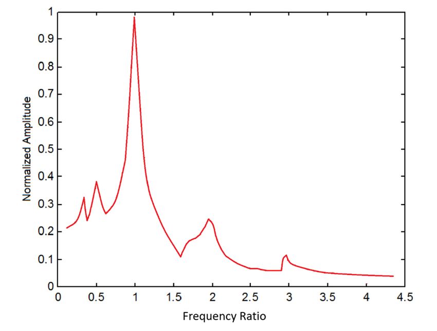
             The corresponding periodogram power spectral density estimate of δθ and waterfall plot of the
     The corresponding
     Thespectra
         corresponding      periodogram
                            periodogram     power spectral    density estimate of     and
                                                                                      and waterfall
                                                                                           waterfall plot
                                                                                                        plot of
                                                                                                             of the
                of δθ are shown in Figures 9power
                                             and 10. spectral density estimate of                               the
spectra of
spectra of      are shown    in Figures  9  and
                are shown in Figures 9 and 10.   10.
Inventions  2018,
  Inventions2018, 3,3,53x FOR PEER REVIEW
             2018,3,                                                                                                             9 of 10
Inventions           x FOR PEER REVIEW                                                                                           9 9ofof1010

                                    Figure9.
                                   Figure
                                   Figure 9.9.Periodogram
                                               Periodogrampower
                                              Periodogram  powerspectral
                                                          power   spectraldensity
                                                                 spectral  densityof
                                                                          density ofofδθ.. .

                                                  Figure 10.Waterfall
                                                 Figure      Waterfall spectrum.
                                                 Figure 10.
                                                        10. Waterfall spectrum.
                                                                      spectrum.

5.5. Conclusions
5. Conclusions
   Conclusions
      InIn thiswork,
                  work, nonlinearvibrations
                                         vibrations ofone-wayone-way clutchininvehicle
                                                                                    vehicle alternatorsystemsystem weremodeled modeled
      In this
           this work, nonlinear
                         nonlinear vibrations of       of one-way clutch
                                                                      clutch in vehicle alternator
                                                                                             alternator system were  were modeled
  and analyzed.AAspecial
and                      special attentionwas     was paidtotocomprehensive
                                                                   comprehensive resonanceproperties properties ofthe   the nonlinear
and analyzed.
      analyzed. A special attentionattention was paid  paid to comprehensive resonance
                                                                                     resonance properties of      of the nonlinear
                                                                                                                             nonlinear
  system
system       with   bilinear    stiffness    non-smooth        features. A   two   degrees-of-freedom         lumped        parameters
system with       bilinear stiffness
           with bilinear      stiffness non-smooth
                                           non-smooth features.
                                                             features. A   two degrees-of-freedom
                                                                        A two    degrees-of-freedom lumped   lumped parameters
                                                                                                                          parameters
  model wasemployed
model            employed toaccount account fortorsional
                                                    torsional vibrationsofofthe  the accessorysystemsystem withone-way
                                                                                                                     one-way clutch
model waswas employed to       to account for for torsional vibrations
                                                                vibrations of the accessory
                                                                                     accessory system with  with one-way clutch  clutch
  and
and      the
       the      model
              model       was
                        was        then
                                 then      simplified
                                        simplified       asas a a  one
                                                                  one   degree-of-freedom
                                                                       degree-of-freedom            system
                                                                                                   system    soso asas  toto derive
                                                                                                                               derive a a
and the model was then simplified as a one degree-of-freedom system so as to derive a comprehensive
  comprehensiveclosed
comprehensive           closedform  formsolution.
                                             solution.AAnon-smooth
                                                               non-smooth transformationwas          wasusedusedtotoanalyzeanalyzethe the
closed form solution.          A non-smooth          transformation wastransformation
                                                                               used to analyze the simplified              model and
  simplified modeland
simplified                andderive
                                  derivethethesolution.
                                                solution.Our  Our theoreticalanalysis
                                                                                 analysis hasshown shownthatthatthe
                                                                                                                  themathematical
                                                                                                                        mathematical
derive the modelsolution. Our        theoretical      analysis theoretical
                                                                  has shown that thehas      mathematical       model       is capable
  model
model     isis capable
             capable    ofof  predicting
                            predicting      a a  full
                                               full   range
                                                    range      of
                                                              of   dynamic
                                                                 dynamic      responses
                                                                            responses        properties
                                                                                           properties     including
                                                                                                        including      thetheprimary,
                                                                                                                               primary,
of predicting a full range of dynamic responses properties including the primary, subharmonic and
  subharmonic
subharmonic         and
                  and     superharmonic
                        superharmonic            resonances.
                                               resonances.        Numerical    analysis    was   conducted     for the   two    degrees-
superharmonic        resonances.      Numerical       analysisNumerical      analysis
                                                                 was conducted      for was    conducted
                                                                                         the two             for the two degrees-
                                                                                                    degrees-of-freedom         lumped
  of-freedomlumped
of-freedom        lumpedparameters
                               parametersmodel,  model,which
                                                           whichpinpointed
                                                                     pinpointedthe  the truedominant
                                                                                                 dominantnonlinear
                                                                                                               nonlinearvibration
                                                                                                                               vibration
parameters model,         which pinpointed          the true dominant       nonlineartrue vibration modes.       A global analysis
  modes.
modes.        A   global    analysis
            A globalscenarios
                          analysisthat    showed
                                        showed         different
                                                      different     scenarios
                                                                   scenarios      that    allowed
                                                                                that understanding    an
                                                                                        allowed an in-depthin-depth       and    general
                                                                                                                       and general
showed different                            allowed     an in-depth    and general                         of the one-way        clutch
  understanding ofthe
understanding              theone-way
                                  one-wayclutchclutch dynamicstotobebedeveloped,
                                                                              developed, whereasthe       the numericalanalysis analysis
dynamics to be of    developed,       whereas thedynamics
                                                        numerical analysis helped towhereas    elaborate thenumerical
                                                                                                                detailed vibration
  helped toelaborate
helped          elaboratethe thedetailed
                                    detailedvibration
                                                vibrationpatterns
                                                              patternsrelated
                                                                        relatedtotospecific
                                                                                      specificparameters
                                                                                                  parametersand  anddefine
                                                                                                                        definecritical
                                                                                                                                  critical
patternstorelated      to specific     parameters and          define critical behaviors        of the system.      It is noted     that
  behaviors
behaviors        of
               of thethe   system.
                         system.and     It  is  noted
                                      It isanalyzing
                                              noted that  that   conventionally
                                                               conventionally        modeling
                                                                                   modeling         and
                                                                                                   and    analyzing
                                                                                                        analyzing          of  torsional
                                                                                                                         of torsional
conventionally       modeling                             of torsional   vibrations     of engine    front-end     accessory      drive
  vibrationsofofengine
vibrations          engine front-endaccessoryaccessory drivesystemsystemhave
                                                                          havetreated
                                                                                  treatedrealrealglobal
                                                                                                  globalsystem
                                                                                                          system tobebea amultiple
                                                                                                                                multiple
system have       treatedfront-end
                             real global system drive    to be a multiple      degree-of-freedom         systemto   with sufficient
  degree-of-freedom
degree-of-freedom           system
                          system        with    sufficient
                                      withparameter
                                              sufficientsystemaccuracy.
                                                            accuracy.     As
                                                                        As usedsuch,
                                                                             such,inthethe  lumped
                                                                                           lumped      parameter
                                                                                                      parameter        system
                                                                                                                     system for   model
                                                                                                                                 model
accuracy. As such, the          lumped                              model              this   paper is  accurate enough              the
  used
used     in  this
       in this of paper
                 paper     is  accurate
                         is accurate        enough
                                         enough        for  the  application   of  alternator    clutch
                                                     for the application of alternator clutch subsystem. subsystem.
application         alternator     clutch   subsystem.
  AuthorContributions:
Author    Contributions:
         Contributions:     Conceptualization,
                          Conceptualization,
                        Conceptualization,           G.C.
                                              G.C. G.C.
                                                    and       andMethodology,
                                                            and
                                                          M.Q.;      M.Q.; Methodology,
                                                                   M.Q.;    Methodology,       G.C.;
                                                                                             G.C.;
                                                                                G.C.; Software,        Software,
                                                                                                     Software,
                                                                                                 X.X.;             X.X.;
                                                                                                       Validation,X.X.;
                                                                                                                   J.C.,
  Validation,
P.L.; Formal  J.C., P.L.;
             Analysis,    Formal
                       G.C., X. X.; Analysis,  G.C.,
                                    Investigation,    X.
                                                   J.C.,  X.;
                                                         P. L., Investigation,
                                                                X.X.           J.C., P.
Validation, J.C., P.L.; Formal Analysis, G.C., X. X.; Investigation, J.C., P. L., X.X.  L., X.X.
 Funding:This
Funding:  Thisresearch
               researchwas
                        wasfunded
                            fundedby
                                   byALT
                                      ALTAmerica
                                          AmericaINC
                                                  INCgrant
                                                      grantnumber
                                                            numberMURC216132.
                                                                   MURC216132.
Inventions 2018, 3, 53                                                                                         10 of 10

Funding: This research was funded by ALT America INC grant number MURC216132.
Conflicts of Interest: The authors declare no conflict of interest.

References
1.    Abrate, S. Vibrations of belts and belt drives. Mech. Mach. Theory 1992, 27, 645–659. [CrossRef]
2.    Beikmann, R.S.; Perkins, N.C.; Ulsoy, A.G. Design and analysis of automotive serpentine belt drive systems
      for steady-state performance. ASME J. Mech. Des. 1997, 119, 162–168. [CrossRef]
3.    Sheng, G.; Liu, K.; Otramba, J.; Pang, J.; Dukkipati, R.V.; Oatu, M. Model and experimental investigation of
      belt noise in automotive accessory belt drive. Int. J. Veh. Noise Vib. 2004, 1, 68–82. [CrossRef]
4.    King, R.; Monahan, R. Alternator pulley with integral overrunning clutch for reduction of belt noise.
      SAE Tech. Pap. 1999, 27–32. [CrossRef]
5.    Xu, J.; Antchak, J. New technology to improve the performance of front end accessory drive system.
      SAE Tech. Pap. 2004. [CrossRef]
6.    Cooley, J.; Chen, G. One-Way over-Running Alternator Clutch. U.S. Patent 5598913A, 7 June 1995.
7.    Michelotti, A.; Paza, A.L.; Maurici, A.; Foppa, C.; Drabison, J.S.; Morris, Z.; Monahan, R.E. Functional testing
      of alternator pulleys in chassis dynamometer. SAE Tech. Pap. 2013. [CrossRef]
8.    Michelotti, A.; Paza, A.L.; Maurici, A.; Foppa, C. Future trends in the conceptual design alternator pulleys.
      SAE Tech. Pap. 2012. [CrossRef]
9.    Fitz, F.; Cali, C. Controlled alternator decoupling for reduced noise and vibration. SAE Tech. Pap. 2010.
      [CrossRef]
10.   Balaji, R.; Mockensturm, E.M. Dynamic analysis of a front-end accessory drive with a decoupler/isolator.
      Int. J. Veh. Des. 2005, 39, 208–231. [CrossRef]
11.   Ding, H.; Zu, J.W. Steady-state responses of pulley-belt systems with a one-way clutch and belt bending
      stiffness. J. Vib. Acoust. 2014, 136. [CrossRef]
12.   Ding, J.; Hu, Q. Equilibria and free vibration of a two-pulley belt-driven system with belt bending stiffness.
      Acta Mech. 2017, 228, 3307–3328. [CrossRef]
13.   Zhu, F.; Parker, R.G. Non-linear dynamics of a one-way clutch in belt-pulley systems. J. Sound Vib. 2005,
      279, 285–308. [CrossRef]
14.   Zeng, X.; Shangguan, W. Modeling and optimization dynamic performances for an engine front end accessory
      drive system with overrunning alternator decoupler. Int. J. Veh. Noise Vib. 2012, 8, 261–274. [CrossRef]
15.   Michelotti, A.; Pastorelli, P.; Ferreira, A.; Berto, L.; Takemori, C.K. In-vehicle experimental tests to evaluate
      the performance of alternator pulleys. SAE Tech. Pap. 2017. [CrossRef]
16.   Pilipchuk, V.N. Analytical study of vibrating systems with strong non-linearities by employing saw-tooth
      time transformation. J. Sound Vib. 1996, 192, 43–64. [CrossRef]
17.   Pilipchuk, V.N.; Vakakis, A.F.; Azeez, M.A.F. Study of a class of subharmonic motions using a non-smooth
      temporal transformation (NSTT). Phys. D: Nonlinear Phenom. 1997, 100, 145–164. [CrossRef]
18.   Pastorelli, P.; Michelotti, A.; Berto, L.; Ferreira, A. Analytical models for spring one-way clutch and torsional
      vibration dampening systems with experimental correlation. SAE Tech. Pap. 2017. [CrossRef]

                         © 2018 by the authors. Licensee MDPI, Basel, Switzerland. This article is an open access
                         article distributed under the terms and conditions of the Creative Commons Attribution
                         (CC BY) license (http://creativecommons.org/licenses/by/4.0/).
You can also read