OPERATOR'S MANUAL WHEEL TRIMMER WT-1610SP
←
→
Page content transcription
If your browser does not render page correctly, please read the page content below
OPERATOR’S MANUAL
                   WHEEL TRIMMER
                              WT-1610SP

                                WARNING
                         Read and understand all provided literature before use.
                         Failure to do so could result in serious injury.

                                WARNING
                         Cancer and Reproductive Harm
                         www.P65Warnings.ca.gov

99922205843
© 06/2022 ECHO Incorporated                                      www.echo-usa.com
Before You Begin
DEAR ECHO ® CUSTOMER
Thank you for purchasing an ECHO product. The ECHO line is designed, tested, and manufactured to give years of
dependable performance. To keep your machine operating at peak efficiency, it is necessary to adjust it correctly and make
regular inspections. The following pages will assist you in the operation and maintenance of your machine. Please read and
understand this manual before operating your machine.
ECHO Consumer Product Support
If you require assistance or have questions concerning the application, operation, or maintenance of this product, call the
ECHO Consumer Product Support Department at 1-800-432-ECHO (3246) from 8:00 am to 5:00 pm (Central Standard
Time) Monday through Friday. Before calling, please know the model and serial number of your unit.
This document is based on information available at the time of its publication. ECHO is continually making improvements
and developing new equipment. In doing so, we reserve the right to make changes or add improvements to our product
without obligation for equipment previously sold.
Product Registration
Register your ECHO equipment on-line at www.echo-usa.com or by filling out the product registration sheet included in this
manual. Registering your product confirms warranty coverage and provides a direct link to ECHO if we find it necessary to
contact you.

SERVICE                                                        PARTS/SERIAL NUMBER
Service of this product during the warranty period must be     Genuine ECHO Parts and Assemblies for your ECHO
performed by an Authorized ECHO Service Dealer. For            products are available only from an Authorized ECHO
the name and address of the Authorized ECHO Service            Dealer. When you do need to buy parts always have the
Dealer nearest you, ask your retailer or call: 1-800-432-      Model Number and Serial Number of the unit with you. For
ECHO (3246). Dealer information is also available on our       future reference write them in the space provided below.
Web Site www.echo-usa.com. When presenting your unit
for Warranty service/repairs, proof of purchase is required.     Model No.
FOR ENGINE SERVICE OR PARTS
For engine service or parts, contact your nearest authorized     Serial No.
engine dealer. ECHO does not handle any parts, repairs or
warranties for engines.

ADDITIONAL LITERATURE
In addition to finding information online, information
is available from your Authorized ECHO Service
Dealer, or by contacting ECHO Inc.,
400 Oakwood Road, Lake Zurich, IL 60047
1-800-432-ECHO (3246)                                                                Serial Number Location

©2022 ECHO Incorporated. All Rights Reserved.
WARRANTY                                                         A. Tune-ups – Air filters, gas filters, carburetors, spark
                                                                 plugs, filters, oil changes
Limited Warranty Statement                                       B. Wear items – Recoil starter rope, wheels, bearings,
                                                                 belts, pulleys, chipper blades, shredder flails or knives.

                                                                                                                                   ENGLISH
ECHO Incorporated warrants to the original retail pur-           C. IMPORTANT: Some components not covered under t
chaser that this ECHO® brand outdoor product is free from        his warranty may still be covered by a separate warranty
defects in material and workmanship and agrees to repair         issued by the engine manufacturer. Please see the Engine
or replace at ECHO Incorporated’s discretion, any defective      Manufacturer Warranty (if any) supplied with this product
product free of charge within these time periods from the        for further details.
date of purchase.
                                                                 ECHO Incorporated reserves the right to change or im-
  •     3 Year Consumer/Homeowner                                prove the design of this product without assuming any
  •     1 Year Commercial                                        obligation to modify any product previously manufactured.
  •     90 Days – For Rental Use
  •     90 Days Accessories and Replacement Parts                All implied warranties are limited in duration to the stated
                                                                 warranty period. Accordingly, any such implied warranties
This warranty extends to the original retail purchaser only      including merchantability, fitness for a particular purpose, or
and commences on the date of the original retail purchase.       otherwise, are disclaimed in their entirety after the expi-
Any part of this product found, in the reasonable judg-          ration of the appropriate three-year, one-year, or 90 day
ment of ECHO Incorporated, to be defective in material or        warranty period. ECHO incorporated’s obligation under
workmanship will be repaired or replaced without charge          this warranty is strictly and exclusively limited to the repair
for parts and labor by an authorized ECHO dealer. Repair         or replacement of defective parts and ECHO incorporated
parts and accessories replaced under this warranty are           does not assume or authorize anyone to assume for them
warranted only for the balance of the original warranty          any other obligation. Some states do not allow limitations
period.                                                          on how long an implied warranty lasts, so the above limita-
                                                                 tion may not apply to you. ECHO incorporated assumes no
The product, including any defective part, must be returned      responsibility for incidental, consequential, or other dam-
to an authorized ECHO dealer within the warranty period.         ages including, but not limited to, expense of returning the
The expense of delivering the product to the dealer for          product to an authorized dealer for ECHO brand outdoor
warranty work and the expense of returning it back to the        products and expense of delivering it back to the owner,
owner after repair or replacement will be paid by the owner.     mechanic’s travel time, telephone or telegram charges,
ECHO Incorporated’s responsibility in respect to claims is       rental of a like product during the time warranty service is
limited to making the required repairs or replacements and       being performed, travel, loss or damage to personal proper-
no claim of breach of warranty shall be cause for cancella-      ty, loss of revenue, loss of use of the product, loss of time,
tion or rescission of the contract of sale of any ECHO brand     or inconvenience. Some states do not allow the exclusion
outdoor product. Proof of purchase will be required by the       or limitation of incidental or consequential damages, so the
dealer to substantiate any warranty claim. All warranty work     above limitation or exclusion may not apply to you.
must be performed by an authorized ECHO dealer.
                                                                 This warranty gives you specific legal rights, and you may
This warranty does not cover any product that has been           also have other rights which vary from state to state.
subject to misuse, neglect, negligence, or accident, or that
has been operated in any way contrary to the operating           This warranty applies to ECHO brand Chipper Shredders
instructions as specified in the Operator’s Manual. This         and Wheeled Trimmers manufactured by or for ECHO In-
warranty does not apply to any damage to the product that        corporated and sold in the United States and Canada.
is the result of improper maintenance or to any product
that has been altered or modified. The warranty does not         To locate your nearest authorized ECHO dealer, visit www.
extend to repairs made necessary by normal wear or by the        ECHO-usa.com or dial 1-800-432-ECHO (3246).
use of parts or accessories which are either incompatible
with the ECHO brand outdoor product, or that adversely
affect its operation, performance, or durability. In addition,
this warranty does not cover wear to normal items such as,
but not limited to:

                                                     ECHO Incorporated
                                                      400 Oakwood Rd.
                                                    Lake Zurich, IL 60047
                                                   1-800-432-ECHO (3246)                                    99922205585
                                                     www.echo-usa.com                                       12/20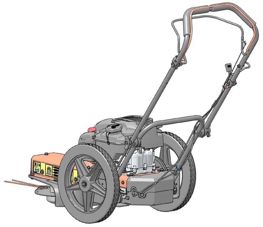
TABLE OF CONTENTS
1   SAFETY.................................................................................................................................................................... 1
    1.1 SAFETY ALERT SYMBOL..................................................................................................................................................... 1
    1.2 FIRE HAZARD INFORMATION............................................................................................................................................. 1
    1.3 BEFORE OPERATING........................................................................................................................................................... 1
    1.4 OPERATION SAFETY............................................................................................................................................................ 2
    1.5 MAINTENANCE/STORAGE SAFETY................................................................................................................................... 2
    1.6 SAFETY DECAL LOCATIONS.............................................................................................................................................. 3

2   ASSEMBLY.............................................................................................................................................................. 4
    2.1 ADJUST THE HANDLE BAR................................................................................................................................................. 4
    2.2 ADD OIL TO ENGINE............................................................................................................................................................. 4
    2.3 FILL THE FUEL TANK............................................................................................................................................................ 4

3   FEATURES & CONTROLS..................................................................................................................................... 5

4   OPERATION............................................................................................................................................................. 6
    4.1 STARTING THE TRIMMER................................................................................................................................................... 6
    4.2 STOPPING THE TRIMMER................................................................................................................................................... 6
    4.3 TRIMMING GUIDE................................................................................................................................................................. 6
    4.4 SELF-PROPELLED OPERATION......................................................................................................................................... 7

5   SERVICE & MAINTENANCE.................................................................................................................................. 8
    5.1 MAINTENANCE SCHEDULE................................................................................................................................................ 8
    5.2 ENGINE MAINTENANCE...................................................................................................................................................... 8
    5.3 CUTTING HEIGHT ADJUSTMENT....................................................................................................................................... 9
    5.4 CUTTING STRING REPLACEMENT.................................................................................................................................... 9
    5.5 DRIVE BELT CHECKING, TENSIONING, AND REPLACEMENT.................................................................................... 10
    5.6 TRANSMISSION BELT/CHAINS TENSIONING AND REPLACEMENT...........................................................................11

6   TROUBLESHOOTING........................................................................................................................................... 12

7   SPECIFICATIONS................................................................................................................................................. 14
    7.1 BOLT TORQUE..................................................................................................................................................................... 15

8   OPTIONS................................................................................................................................................................ 16

9   PRODUCT REGISTRATION................................................................................................................................. 17
1                SAFETY

                                                                                                                           ENGLISH
    Section

                                                              The engine on your power equipment, like most outdoor
 1.1 SAFETY ALERT SYMBOL                                      power equipment, is an internal combustion engine that
                                                              burns gasoline or diesel fuel (hydrocarbons). If operating
                                                              your power equipment in affected areas, it must be
                                                              equipped with a spark arrestor in continuous effective
                                                              working order. The spark arrestor must be attached to the
                                                              engine exhaust system in such a manner that flames or
                                                              heat from the system will not ignite flammable material.
                                                              Failure of the owner/operator of the equipment to comply
                                                              with federal, state, and local laws may subject him or her
The Owner/Operator’s manual uses this symbol to alert         to fines and/or other penalties. Contact your local fire
you of potential hazards. Whenever you see this symbol,       marshal or forest service for specific information about
read and obey the safety message that follows it. Failure     which regulations apply in your area.
to obey the safety message could result in personal injury,
death or property damage.                                     The standard muffler installed on the engine is spark
                                                              arrestor capable. Spark arrestors require regular
                                                              maintenance. See the Service & Maintenance section of
                                                              this manual for more information.
                    DANGER                                    Metal cutting components, including the mow ball, can
 Indicates an imminently hazardous situation that, if not     also create sparks if they strike rocks, metal, or other
 avoided, will result in death or serious injury.             hard objects. Contact local fire authorities for laws or
                                                              regulations regarding fire prevention requirements.

                   WARNING                                     1.3 BEFORE OPERATING
 Indicates a potentially hazardous situation that, if not
 avoided, could result in death or serious injury.

                   CAUTION                                    1. Read and understand this owner’s manual. Be
                                                                 completely familiar with the controls and the proper
 Indicates a potentially hazardous situation that, if not        use of this equipment.
 avoided, may result in minor or moderate injury.
                                                              2. Familiarize yourself with all of the safety and
                                                                 operating decals on this equipment and on any of its
 1.2 FIRE HAZARD INFORMATION                                     attachments or accessories.

Operation of this equipment may create sparks that            3. Keep safety decals clean and legible. Replace
can start fires around dry vegetation. This unit may be          missing or illegible safety decals.
equipped with a spark arrester to prevent discharge of        4. Obtain and wear safety glasses and
hot particles from the engine. The                               use hearing protection at all times
spark arrester may be a standard or                              when operating this machine.
an optional part, depending on the                            5. Avoid wearing loose fitted clothing.
engine type. In some areas, it is illegal                        Never operate this machine while
to operate an engine without a spark                             wearing clothing with drawstrings that could wrap
arrester. Check local, state, and federal                        around or get caught in the machine.
laws and regulations. A spark arrester
is available from authorized servicing
dealers.

                                                  WHEELED TRIMMER                                                     1
SAFETY

6. Do not operate this machine if you
   are under the influence of alcohol,
                                                                1.4 OPERATION SAFETY
   medications, or substances that
   can affect your vision, balance or                          1. Keep hands and feet out of cutting area while machine
   judgement. Do not operate if tired                             is operating to avoid serious personal injury. Stop and
   or ill. You must be in good health to                          allow machine to come to a complete stop before
   operate this machine safely.                                   clearing obstructions.

7. Do not operate this equipment in the vicinity of            2. Set up your work site so you are not endangering
   bystanders. Keep the area of operation clear of all            traffic and the public. Take great care to provide
   persons, particularly small children. It is recommended        adequate warnings.
   that bystanders keep at least 50 feet (15 meters)           3. Keep the machine clear of debris and other
   away from the area of operation.                               accumulations.
8. Do not allow children to operate this equipment.            4. When the trimmer bail is engaged, the trimmer disk
9. Use only in daylight or good artificial light.                 is rotating. Do not attempt to inspect or service the
                                                                  machine while the trimmer disk is rotating.
10. Do not run this equipment in an enclosed area. Engine
    exhaust contains carbon monoxide gas, a deadly             5. Maintain firm control of the machine during operation
    poison that is odorless, colorless and tasteless.             to prevent tipping. Always be sure of your footing.
    Do not operate this equipment in or near buildings,        6. Shut off the power source, and make sure all moving
    windows or air conditioners.                                  parts have come to a complete stop before inspecting
11. Always use an approved fuel container. Do not                 or servicing any part of the machine.
    remove gas cap or add fuel when engine is running.                                   *Do not operate over an angle of
    Add fuel to a cool engine only.                                                      15°. Higher angles may cause
12. Do not fill fuel tank indoors. Keep open flames, sparks,                             damage to your MACHINE.
                                                                                  15 o
    smoking materials and other sources of combustion
    away from fuel.
13. Do not operate machine without shields in place.
    Failure to do so may cause serious injury or death.         1.5 MAINTENANCE/STORAGE SAFETY
14. Keep all guards, deflectors, and shields in good           1. Before inspecting, servicing, storing, or changing an
    working condition.                                            accessory, shut off the machine and make sure all
15. Before inspecting or servicing any part of this machine,      moving parts have come to a complete stop.
    shut off the machine and make sure all moving parts        2. Replace any missing or unreadable safety decals.
    have come to a complete stop.                                 Refer to the safety decal section for part numbers.
16. Check that all screws, nuts, bolts, and other fasteners    3. Allow machine to cool before storing in an enclosure.
    are secured, tightened and in proper working condition
    before starting the machine.                               4. Store the machine out of reach of children and where
                                                                  fuel vapors will not reach an open flame or spark.
17. Do not transport or move machine while it is operating
    or running.                                                5. Never store this machine with fuel in the fuel tank
                                                                  inside a building where fumes may be ignited by
                                                                  an open flame or spark. Ignition sources can be hot
                                                                  water and space heaters, furnaces, clothes dryers,
                                                                  stoves, electric motors, etc.
                                                               6. Drain the fuel and dispose of it in a safe manner for
                                                                  storage periods of three months or more.

2                                                   WHEELED TRIMMER
SAFETY

  1.6 SAFETY DECAL LOCATIONS

                                                                                                                                                      ENGLISH
Familiarize yourself with all of the safety and operational decals on the machine and the associated hazards. See the
engine owner’s manual or contact the engine manufacturer for engine safety instructions and decals. Make certain that
all safety and operating decals on this machine are kept clean and in good condition. Decals that need replacement
must be applied to their original locations.

  1       PN YH653000230

Do not operate this equipment in the vicinity of bystanders.
Do not allow children to operate this equipment. Always
stand clear of discharge area when operating this machine.
Keep face and body away from discharge areas.
Do not allow hands or any part of body or clothing near any moving part to avoid serious personal injury.
Obtain and wear safety glasses and use hearing protection at all times when operating this machine.

  2       PN YH653000240

Before inspecting or servicing any part of this machine, shut off power source, disconnect spark plug wire from spark plug and make sure all moving
parts have come to a complete stop.
Keep machine clear of debris and other accumulations. Build up of debris on machine can cause a fire.

          PN YH653000290
  3
Operation of this equipment may create sparks that can start fires
around dry vegetation. A spark arrestor may be required. The operator
should contact local fire agencies for laws or regulations relating to fire
prevention requirements.

                                                                        1

                                3                                                                    2

                                                                WHEELED TRIMMER                                                                  3
2                 ASSEMBLY
     Section

    2.1 ADJUST THE HANDLE BAR                                     2.3 FILL THE FUEL TANK
1. Open shipping box and remove packing material.
2. Loosen T-handles on handle bar. Raise upper portion
   of handle bar to desired position. Tighten T-handles.
                                                                                   WARNING
3. Cut the two corners of the shipping box so that the                             Gasoline and diesel fuels are highly
   trimmer can be rolled out onto the floor.                                       flammable and their vapors are
                                                                                   explosive. To prevent personal injury or
4. Install recoil rope into recoil loop on handlebar.
                                                                                   property damage:
5. Rotate recoil loop to make contact with handle bar                              Store fuel only in approved containers,
   and capture recoil rope.                                                        in well ventilated, unoccupied buildings,
                                                                                   away from sparks or flames. A container
    2.2 ADD OIL TO ENGINE                                                          with a capacity of 2 gallons or less with
                                                                                   a pouring spout is recommended. Do
Check the oil level and, if needed, fill the engine crankcase    not fill the fuel tank while the engine is hot or running,
with the type and amount of oil specified in the engine          since spilled fuel could ignite if it comes in contact
owner’s manual.                                                  with hot parts or sparks from ignition. Do not start the
                                                                 engine near spilled fuel. Never use fuel as a cleaning
                                                                 agent.
                                                                 DO NOT MIX OIL WITH FUEL.

                                                                Use only those types of fuels that are recommended in
                                                                your engine owner’s manual.
                                                                To add fuel:
                                                                1. Stop engine, wait for all parts to stop moving and
                                                                   disconnect spark plug wire. Allow the engine and
                                                                   muffler to cool for at least three minutes.
                                                                2. Clean area around fuel fill cap and remove cap.
                                                                3. Using a clean funnel, fill fuel tank to 1/2" below bottom
                                                                   of filler neck to provide space for any fuel expansion.
                                                                   Install fuel fill cap securely and wipe up any spilled
                                                                   gasoline.

4                                                   WHEELED TRIMMER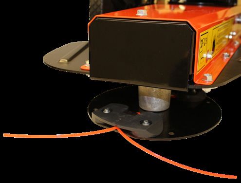
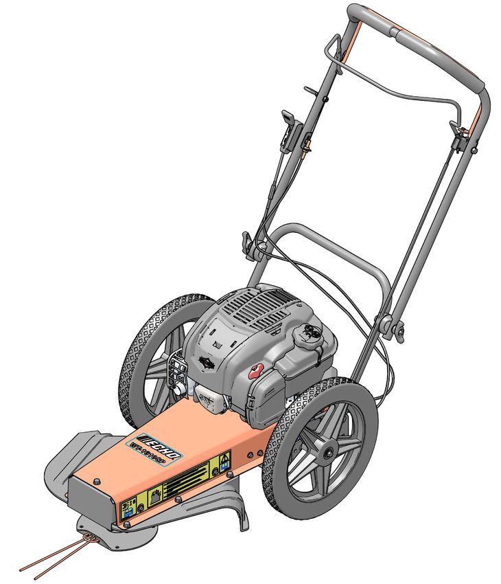
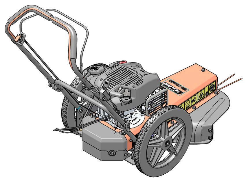
3                  FEATURES & CONTROLS

                                                                                                                              ENGLISH
   Section

Understanding how your machine works will help you achieve the best results when using your trimmer. The following
descriptions define the features and controls of your machine.
REFER TO ENGINE OWNER’S MANUAL FOR FURTHER ENGINE OPERATING INSTRUCTIONS.

1. CHOKE LEVER                                                    7. SELF-PROPELLED BAIL
   Use when starting a cold engine.                                  Engages the transmission. Pull back the self-propel
2. TRIMMER BAIL                                                      bail located in front of the handlebar to start moving
                                                                     forward.
   To start the trimmer, lift up the trimmer bail located
   below the handle bar. When the engine is running               8. SHIFT LEVER
   and the trimmer bail is engaged, the trimmer disk is              Used to adjust the trimmer speed. Position 1 is the
   rotating. Release the trimmer bail to stop the trimmer.           slowest and position 3 is the fastest. The ground
   Wait until the trimmer disk has stopped rotating to               speed ranges from 1, 1.5, and 2 mph.
   inspect or service the trimmer.
3. RECOIL STARTER
   Used to start engine. Grasp handle and slowly pull
   until resistance is felt. After resistance is felt, pull the
   cord quickly to start the engine and prevent kickback.
                                                                                         7                      2
4. HANDLE BAR ADJUSTMENT/FOLDING HANDLE
   BAR
   Loosen T-handle to adjust handle bar position.
   Tighten T-handle at desired location. Handle bar                                 8
   can be folded down over the trimmer for hauling or
   storage.
5. TRIMMER PLATE
   Attach trimmer string or replace with Proline Head or                    4
   No Spark Mow Ball.
6. FRONT COVER
   Cover can be removed for: replacing a belt, flipping
   the trimmer plate, or install/removal of Proline Head                    3
   or No Spark Mow Ball.

                                                      6
                                                                                               1

                                                                        5

                                                     WHEELED TRIMMER                                                     5
4               OPERATION
      Section

As with any other piece of outdoor power equipment,
getting the feel for how your machine operates and                                WARNING
getting to know the best techniques for particular jobs are
important to overall good performance.                          Allow the machine to come to complete stop before
                                                                inspection or servicing. You can tell when the machine
TRIMMING OPERATION                                              has come to a complete stop when the trimmer disk is
                                                                not rotating.
The trimming operation takes place under the body of the
trimmer, where trimmer string is mounted to a rotating
disk. Material is trimmed and propelled out the edges of
the trimmer.                                                     4.3 TRIMMING GUIDE

                                                               The intended use of the Wheeled Trimmer is trimming,
                     WARNING                                   mowing and edging. The following guidelines can help
                                                               you get started.
    Before operating your machine, be sure you read
                                                               1. Run unit at full operating speed before starting to trim,
    and understand all safety, controls and operating
                                                                  mow or edge.
    instructions in this owner’s manual and on your
    machine. Failure to follow these instructions can result   2. To begin trimming, start the engine, place the trimmer
    in serious injury or property damage.                         head on the ground and begin walking slowly.
                                                               3. The wheels should remain on the ground at all times
                                                                  to prevent undue pressure on the trimmer head.
    4.1 STARTING THE TRIMMER                                   4. The cutting radius is dependant on the amount of
                                                                  cutting string used and type of application.
Move the machine to a clear, level area outdoors before
                                                               5. For difficult conditions and edging, using less than the
starting. Do not operate in the vicinity of bystanders. Make
                                                                  full cutting radius is recommended.
sure the engine is clean and debris has not accumulated
on the engine or around the muffler.                           6. If mowing a large open area, mow in a counter-
                                                                  clockwise direction, working from the outside towards
1. Check engine oil level before starting (see Engine
                                                                  the center. Cut grass discharges to the right side of
   Owners Manual).
                                                                  the trimmer.
2. Turn choke lever to ON.
3. Lift trimmer bail to handle bar.
4. Grasp the recoil starter cord handle and slowly pull
                                                                                  WARNING
   until resistance is felt, then pull quickly to start the     Inspect and clean engine before each use. Debris
   engine and prevent kickback. Repeat if necessary.            accumulation around the muffler can cause a fire.
5. Allow engine to warm up and turn the choke OFF.

    4.2 STOPPING THE TRIMMER

Release the trimmer bail.                                                                                15 o

                                                               *Do not operate over an angle of 15°. Higher angles may
                                                               cause damage to your MACHINE.

6                                                    WHEELED TRIMMER
OPERATION
4.4 SELF-PROPELLED OPERATION
ENGLISH
The Wheeled Trimmer can be used in either push or self-propelled mode. Check engine oil level before starting (see
Engine Owners Manual).
1. Pull back on the self-propelled bail located in front of the handlebar to start moving forward.
2. Adjust the trimmer speed with the shift lever. Position 1 is the slowest and position 3 is the quickest. The ground
speed ranges from 1, 1.5 and 2 mph.
3. Operate trimmer safely and as intended.
4. To stop the trimmer release the self-propelled bail.
5. To stop the engine, release the trimmer bail.
WHEELED TRIMMER 75 SERVICE & MAINTENANCE
Section
5.1 MAINTENANCE SCHEDULE
The items listed in this service and maintenance schedule are to be checked, and if necessary, corrective action taken.
This schedule is designed for units operating under normal conditions. If the unit is operating in adverse or severe
conditions, it may be necessary for the items to be checked and serviced more frequently.
SEE ENGINE OWNER’S MANUAL FOR FURTHER ENGINE MAINTENANCE AND TROUBLESHOOTING
INFORMATION.
SERVICE AND MAINTENANCE SCHEDULE
FREQUENCY
REFER TO ENGINE BEFORE AFTER EVERY
MAINTENANCE EVERY
COMPONENT OPERATOR’S EACH FIRST 8
REQUIRED YEAR
MANUAL USE USE HOURS
Air cleaner Check and clean (1) ●
Engine oil Change (1) ●
Check condition
Spark plug ●
and gap
Fuel tank Check/fill ●
All internal and external
Check tightness ●
nuts and bolts
Cooling shrouds Clean (1) ● ●
Belt Check tightness ●
Spark arrestor* Clean ●
Entire machine Clean ●
Starter drive Service ●
(1) Perform more frequently under extremely dusty conditions.
*If equipped
Change oil after first 5-8 hours of use, then every 50 hours or every season.
As the Limited Warranty states, failure by the Owner to perform normal maintenance will void the machine’s
warranty.
5.2 ENGINE MAINTENANCE
Maintenance is essential in preserving engine life. Clean
the engine periodically to remove grass and buildup. The WARNING
engine owners manual addresses cleaning the air filter
and changing the oil. Service engine according to the Clean grass and buildup from the engine periodically.
maintenance schedule in your engine owners manual. Dusty conditions will require frequent cleaning.
Remember to inspect and clean engine cooling fins as
needed.
8 WHEELED TRIMMERSERVICE & MAINTENANCE
WARNING
BEFORE INSPECTING OR SERVICING ANY PART OF THIS MACHINE, SHUT OFF POWER SOURCE, DISCONNECT SPARK PLUG
WIRE FROM SPARK PLUG AND MAKE SURE ALL MOVING PARTS HAVE COME TO A COMPLETE STOP.
ENGLISH
5.3 CUTTING HEIGHT ADJUSTMENT
The standard cutting height is 2-3/4 inches. The cutting 6. Reinstall the mow ball and turn clockwise (when
height can be adjusted down approximately 3/4" by viewed from below) to tighten.
turning the trimmer head disk over. To adjust the cutting
height:
1. Remove front cover.
2. Rotate the mow ball to align the flat spots of the
trimmer shaft with the opening.
3. Use an adjustable wrench or 9/16" (14 mm) wrench
to hold the trimmer shaft. Rotate until the wrench is Front
braced against the trimmer body. Cover
4. To remove, turn the mow ball counterclockwise (when
viewed from below). Use a slip wrench or oil filter
style wrench if mow ball is difficult to remove. Turning Trimmer
Disk
the trimmer plate can also assist with loosening the
mowball.
5. Turn trimmer disk over and replace on trimmer
Mow Ball
spindle.
Figure 5.1, Cutting Height Adjustment
5.4 CUTTING STRING REPLACEMENT
Cutting string is available in two thicknesses, 155 mil
(standard) and 175 mil (heavy duty). The type of string
selected is dependent on the conditions and material
being cut.
Cutting string can be wrapped in a variety of ways. Refer
to Figures 5.2, 5.3, and 5.4 for examples. The wrapping
method and cutting string thickness chosen is ultimately
based on what is determined the best for the operator.
To wrap the cutting string in the standard configuration, Figure 5.2 Wrapping the Cutting String
follow the steps below.
1. Feed the cutting string through the second hole on
either end of the trimmer head leaving approximately
8 inches for the cutting surface. Total recommended
string length is 20 inches.
2. Continue by weaving the cutting string through the
first hole directly beside the second hole used in
step 1. Pull the cutting string tight.
Figure 5.3 Optional Wrapping Method
3. Loop the cutting string back and feed through the first
hole on the opposite end of the trimmer head.
4. Feed through the remaining second hole and pull the
cutting string tight. The cutting strings in the middle
two holes should be the same length. If the length
differs, cut to an even length.
5. Optional method. Tie knot in middle of string. Insert
loose ends through holes in trimmer plate.
Figure 5.4 Optional Wrapping Method
WHEELED TRIMMER 9SERVICE & MAINTENANCE
WARNING
BEFORE INSPECTING OR SERVICING ANY PART OF THIS MACHINE, SHUT OFF POWER SOURCE, DISCONNECT SPARK PLUG
WIRE FROM SPARK PLUG AND MAKE SURE ALL MOVING PARTS HAVE COME TO A COMPLETE STOP.
5.5 DRIVE BELT CHECKING, TENSIONING, AND REPLACEMENT
Check the condition of the drive belt annually or after 20 7. Install cover (5) using four bolts (3) and washers (4).
hours of operation, whichever comes first. If the belt is 8. Move spindle hub forward to apply belt tension.
cracked, frayed, or worn, replace it by following these Tighten four bolts (2).
steps:
9. Replace front cover.
1. Shut off the engine. Disconnect the spark plug wire.
2. Remove the front cover (1).
3. Loosen the four bolts (2) fastening the spindle hub to
the trimmer bottom frame. This will allow the spindle NOTE
hub with the attached trimmer pulley to move freely.
● A belt that is too tight will damage bearings/spindle
4. Remove the four bolts (3) and washers (4) attaching
shaft/belt
the transmission cover (5) to the transmission
mount bracket (6). Remove cover (5) to expose the ● A belt that is too loose will slip and cause premature
transmission and gain access to the belts. failure.
5. Remove worn or broken belt. ● The engine should be placed under load while in
thick grass, if not the belt may be slipping.
6. Install new belt from the front to the back. Feed belt
above the front trimmer pulley and below the rear
pulley.
2 1
3
4
4 6
5
3
Figure 5.1
10 WHEELED TRIMMERSERVICE & MAINTENANCE
WARNING
BEFORE INSPECTING OR SERVICING ANY PART OF THIS MACHINE, SHUT OFF POWER SOURCE, DISCONNECT SPARK PLUG
WIRE FROM SPARK PLUG AND MAKE SURE ALL MOVING PARTS HAVE COME TO A COMPLETE STOP.
ENGLISH
5.6 TRANSMISSION BELT/CHAINS TENSIONING AND REPLACEMENT
See Figure 5.1 for illustration.
1. Shut off the engine. Disconnect the spark plug wire. NOTE
2. Remove the front cover (1). ● A belt that is too tight will damage bearings/spindle
3. Loosen the four bolts (2) fastening the spindle hub to shaft/belt
the trimmer bottom frame. This will allow the spindle ● A belt that is too loose will slip and cause premature
hub with the attached trimmer pulley to move freely. failure.
4. Remove the four bolts (3) and washers (4) attaching ● The engine should be placed under load while in
the transmission cover (5) to the transmission thick grass, if not the belt may be slipping.
mount bracket (6). Remove cover (5) to expose the
transmission and gain access to the belts.
5. Remove drive belt from engine pulley.
6. Remove worn or broken transmission belt.
7. Install new transmission belt and reinstall drive belt.
8. Install cover (5) using four bolts (3) and washers (4).
9. Move spindle hub forward to apply belt tension.
Tighten four bolts (2).
The transmission belt and chains are tensioned by moving
the transmission front to back.
10. Remove the transmission cover (5) as described in
step 4.
11. Loosen the nuts (10) on each end of the transmission
as well as the two on the bottom side of the axle base.
The nuts should be loosened just enough to allow 10
movement.
12. Increase/decrease tension as needed. Tighten nuts
(10) that were loosened in step 11.
13. Reinstall cover (5) using four bolts (3) and washers (4). 10
10
WHEELED TRIMMER 116 TROUBLESHOOTING
Section
Before performing any of the corrections in this troubleshooting chart, refer to the appropriate information contained in
this manual for the correct safety precautions and operating or maintenance procedures. Contact your dealer or ECHO
for service problems with the machine.
PROBLEM POSSIBLE CAUSES REMEDY
Broken or damaged belt Replace belt
Trimmer disk does not
Broken spindle Replace spindle
turn
Failed bearings Replace bearings
Cutting string is too weak Replace with heavier cutting string (.175)
Cutting is slow or Reduce the trimming area by half or raise the
Growth is too thick or heavy
rough trimmer head off the ground
Engine not running at full RPM Speed up engine to full throttle
Cutting string is too long Reduce cutting string length
Trimmer requires Reduce the trimming area by half or raise the
Growth is too thick or heavy
excessive power or trimmer head slightly off the ground
stalls Move spindle hub assembly towards the rear of
Belt too tight
the trimmer
Drive belt squealing or Drive belt is loose or worn Replace drive belt
smoking Worn or damaged pulley Replace pulley
Gas tank is empty Fill gas tank
Spark plug wire is disconnected Connect loose wire to the spark plug
Spark plug is defective Replace spark plug
Remove gas line at carburetor and check for
Gas line is obstructed obstruction. Drain gas tank and refill with fresh
gasoline.
Engine won’t start or is Dirty, stale, water-contaminated gas Drain tank and fill with fresh gasoline
hard to start Put throttle control in run position and crank
Flooded engine
engine several times to clear out excess gas
Dirty or plugged air cleaner or engine Clean or replace air cleaner. Clean cooling fins
cooling fins and shroud area of engine.
Trimmer bail not engaged Engage trimmer bail
Check harness for loose connections or break in
Wire harness connection
wire
12 WHEELED TRIMMERTROUBLESHOOTING
PROBLEM POSSIBLE CAUSES REMEDY
Air filter dirty Clean or replace
ENGLISH
Fuel filter dirty Replace
Engine runs, but dies Fuel vent plugged Clean or replace
or does not accelerate Spark plug dirty/worn Clean and adjust or replace
properly Carburetor vibration Adjust
Cooling system dirty/plugged Clean
Spark arrestor* plugged Clean or replace
Pulley not aligned Align pulleys
Drive belt rolling or
Belt not tensioned properly Tension belt with 70 lbs. of force
falling off pulleys
Spindle bearing failed Replace bearing
Transmission engagement cable is out
Adjust cable on handle bar or at transmission
of adjustment
Wheels do not spin
with transmission bail Transmission belt is slipping See maintenance section on tensioning belt
engaged Sprockets are spinning on shafts Check for roll pins and set screws in sprockets
Chain is off sprockets Check sprocket alignment and tension
*If equipped
WHEELED TRIMMER 137 SPECIFICATIONS
Section
DESCRIPTION ENGLISH METRIC
Engine Briggs & Stratton® 675 EXi Series 163cc
Drive Self-propelled
Fuel capacity 0.8 quarts (0.2 gallon)
Start Recoil
Cutting width 24" 61 cm
Cutting height 1-7/8" and 2-3/4" 4.8 cm and 7 cm
Nylon cutting string 20" 0.155" Cross-Fire ®
50.8 cm 0.39 cm Cross-Fire
Wheel support Ball bearings
Control vibration level < 2.5 m/s²
Noise level 111 dB
Weight 100 lbs. 45.4 kg
Machine Dimensions (L × W × H) 47" × 23" × 43" 119 cm × 58 cm × 109 cm
Spark Arrester Equipped* No
* - If a spark arrester is required it must meet the specifications and performance requirements of local, state, and
federal laws and regulations. A spark arrester is available from authorized servicing dealers.
14 WHEELED TRIMMERSPECIFICATIONS
7.1 BOLT TORQUE
The tables below are for reference purposes only and their use by anyone is entirely voluntary, unless otherwise noted.
ENGLISH
Reliance on their content for any purpose is at the sole risk of that person and any loss or damage resulting from the
use of this information is the responsibility of that person.
SAE SAE 2 SAE 5 SAE 8 BOLT DIAMETER
Grade
and
Head
Markings
BOLT TORQUE*
BOLT DIAMETER (A) SAE 2 SAE 5 SAE 8
NM FT-LB. NM FT-LB. NM FT-LB.
1/4" 7.5 5.5 11 8 16 12
5/16" 15 11 23 17 34 25
3/8" 27 20 41 30 61 45
7/16" 41 30 68 50 95 70
1/2" 68 50 102 75 149 110
9/16" 97 70 149 110 203 150
5/8" 122 90 203 150 312 230
3/4" 217 160 353 260 515 380
7/8" 230 170 542 400 814 600
1" 298 220 786 580 1220 900
1-1/8" 407 300 1085 800 1736 1280
1-1/4" 570 420 2631 1940 2468 1820
METRIC 4.8 8.8 10.9 12.9 BOLT DIAMETER
Grade
and
Head 4.8 8.8 10.9 12.9
Markings
BOLT TORQUE*
BOLT
4.8 8.8 10.9 12.9
DIAMETER (A)
NM FT-LB. NM FT-LB. NM FT-LB. NM FT-LB.
M3 0.5 0.4 – – – – – –
M4 3 2.2 – – – – – –
M5 5 4 – – – – – –
M6 6 4.5 11 8.5 17 12 19 14.5
M8 15 11 28 20 40 30 47 35
M10 29 21 55 40 80 60 95 70
M12 50 37 95 70 140 105 165 120
M14 80 60 150 110 225 165 260 190
M16 125 92 240 175 350 255 400 300
M18 175 125 330 250 475 350 560 410
M20 240 180 475 350 675 500 800 580
M22 330 250 650 475 925 675 1075 800
M24 425 310 825 600 1150 850 1350 1000
M27 625 450 1200 875 1700 1250 2000 1500
*Torque value for bolts and capscrews are identified by their head markings.
Torque figures indicated above are valid for non-greased or non-oiled threads and heads unless otherwise specified. Therefore, do not grease or oil
bolts or capscrews unless otherwise specified in this manual. When using locking elements, increase torque values by 5%.
WHEELED TRIMMER 158 OPTIONS
Section
PART NUMBER DESCRIPTION
102225155 STRING, .155 DIA, CROSS-FIRE (50 Count / 21” Strips)
®
311155066 STRING, .155 DIA, CROSS-FIRE (1 LB. DONUT)
314155056 STRING, .155 DIA, CROSS-FIRE (3 LB. SPOOL)
102225175 STRING, .175 DIA, CROSS-FIRE (50 Count /21” Strips)
311175067 STRING, .175 DIA, CROSS-FIRE (1 LB. DONUT)
314175057 STRING, .175 DIA, CROSS-FIRE (3 LB. SPOOL)
99944400000 KIT, PRO-LINE HEAD
99944400001 KIT, NO SPARK MOW BALL
16 WHEELED TRIMMER9 PRODUCT REGISTRATION
ENGLISH
Section
PRODUCT REGISTRATION
Thank you for choosing ECHO Power Equipment
Please go to http://www.echo-usa.com/Warranty/Register-Your-ECHO to register your new
product on-line. It’s FAST and EASY! NOTE: your information will never be sold or misused
by ECHO, Inc. Registering your purchase enables us to contact you in the unlikely event of
a service update or product recall, and verifies your ownership for warranty consideration.
If you do not have access to the Internet, you can complete the form below and mail to:
ECHO Incorporated, Product Registration, PO Box 1139, Lake Zurich IL 60047.
WHEELED TRIMMER 1718 WHEELED TRIMMER
ECHO INCORPORATED
                                      400 Oakwood Road
                                     Lake Zurich, IL 60047
                                     www.echo-usa.com
Serial Range: 130WTB000001 - 130WTB999999                    79319-00
Manual del Operador
Recortadora de
Ruedas
ESPAÑOL
WT-1610SP
ADVERTENCIA
Lea y comprenda toda la literatura incluida antes de
su uso. Si no lee los manuales, podría sufrir lesiones
graves.
Nota: Este producto cumple con los estándares CAN ICES-2/NMB-2.
ADVERTENCIA
El sistema de escape del motor de este producto contiene
químicos que pueden causar cáncer, defectos congénitos u
otros daños en la reproducción, de acuerdo a lo que se conoce
en el Estado de California.
99922205843
© 06/2022 ECHO Incorporated www.echo-usa.comPrefuncionamiento
ESTIMADO CLIENTE DE ECHO ®
Gracias por adquirir un producto ECHO. La línea ECHO está diseñada, probada y fabricada para brindar años de rendimiento confiable.
Para mantener su máquina funcionando con la máxima eficiencia, es necesario ajustarla correctamente y realizar inspecciones periódicas.
Las siguientes páginas le ayudarán en el funcionamiento y mantenimiento de su máquina. Lea y comprenda este manual antes de operar
su máquina.
Soporte de productos de consumo de ECHO
Si necesita ayuda o tiene preguntas sobre la aplicación, operación o mantenimiento de este producto, llame al Departamento de Soporte
de Productos para el Consumidor de ECHO al 1-800-432-ECHO (3246) de 8:00 am a 5:00 pm (Central Standard Hora) de lunes a
viernes. Antes de llamar, sepa el modelo y el número de serie de su unidad.
Este documento se basa en la información disponible en el momento de su publicación. ECHO está continuamente mejorando y
desarrollando nuevos equipos. Al hacerlo, nos reservamos el derecho de realizar cambios o agregar mejoras a nuestro producto sin
obligación para los equipos vendidos anteriormente.
Registración del producto
Registre su equipo ECHO en línea en www.echo-usa.com o llenando la hoja de registro del producto incluida en este manual. El
registro de su producto confirma la cobertura de la garantía y proporciona un enlace directo a ECHO si lo consideramos necesario para
comunicarnos con usted.
SERVICIO PIEZAS / NÚMERO DE SERIE
El servicio de este producto durante el período de garantía Las piezas y conjuntos originales ECHO para sus productos
debe ser realizado por un distribuidor de servicio ECHO ECHO están disponibles únicamente en un distribuidor
autorizado. Para obtener el nombre y la dirección del autorizado de ECHO. Cuando necesite comprar piezas,
distribuidor de servicio ECHO autorizado más cercano lleve siempre consigo el número de modelo y el número de
a usted, pregunte a su distribuidor o llame al: 1-800-432- serie de la unidad. Para referencia futura, escríbalos en el
ECHO (3246). La información del distribuidor también espacio provisto a continuación.
está disponible en nuestro sitio web www.echo-usa.com.
Al presentar su unidad para servicio / reparaciones bajo N º de Modelo.
garantía, se requiere prueba de compra.
PARA SERVICIO DE MOTOR O PIEZAS
Número de serie.
Para obtener servicio o piezas del motor, comuníquese con
el distribuidor de motores autorizado más cercano. ECHO
no maneja piezas, reparaciones ni garantías para motores.
LITERATURA ADICIONAL
Además de encontrar información en línea, la información
sedisponible en su distribuidor de servicio ECHO
autorizado, oponiéndose en contacto con ECHO Inc.
400 Oakwood Road, Lake Zurich, IL 60047
Serial Number Location
1-800-432-ECHO (3246)
© 2022, ECHO® Incorporated. ,Todos los derechos reservados.GARANTÍA
Declaración de la garantía limitada
ECHO Incorporated garantiza al comprador original al menudeo
que este producto para exteriores de la marca ECHO® carece C. IMPORTANTE: A los componentes que esta garantía no
de defectos en los materiales y en la mano de obra, y acuerda cubra, los podrá cubrir una garantía adicional emitida por el
reparar o remplazar, a la sola discreción de ECHO Incorporated, que fabricante del motor. consulte la garantía del fabricante
cualquier producto defectuoso, sin cargo alguno al comprador, del motor (si la hubiera) que se entregó con el producto para
dentro de los siguientes períodos de tiempo a partir de la fecha conocer más detalles.
de compra.
La Empresa no pagará las reparaciones o los ajustes que se re-
• 3 años consumidor alicen al producto, ni ningún costo ni mano de obra que se lleve a
• 1 año comercial cabo sin la autorización previa de la Empresa. ECHO Incorporat-
• 90 días para uso de alquiler ed se reserva el derecho de cambiar o mejorar el diseño de este
• 90 días accesorios y piezas de repuesto producto sin asumir cualquier obligación de modificar cualquier
producto anteriormente fabricado.
Esta garantía se otorga solamente al comprador original al
menudeo, y comienza en la fecha de la compra original al Todas las garantías implícitas están limitadas en duración según
menudeo. Cualquier parte de este producto que ECHO Incor- el período de garantía declarada. Por consiguiente, cualquier
porated considere, a su criterio razonable, tiene un defecto de garantía implícita, incluso las de comerciabilidad, idoneidad para
ESPAÑOL
materiales o de manufactura se reparará o cambiará sin costo de un propósito en particular, o de cualquier tipo, pierden totalmente
repuestos o mano de obra en un distribuidor ECHO autorizado. su validez después del vencimiento del período de garantía cor-
Los repuestos que se utilicen en reparaciones y los accesorios respondiente de tres años, un años, o noventa días. De confor-
reemplazados amparadas bajo garantía seguirá estando garan- midad con esta garantía, la obligación de echo incorporated se
tizada por la garantía durante el período de garantía restante. limita estricta y exclusivamente a la reparación o remplazo de
El producto, incluida toda pieza defectuosa, debe enviarse a un las piezas defectuosas, y echo incorporated no asume ninguna
distribuidor ECHO autorizado dentro del período de la garantía. otra obligación, ni autoriza a nadie asumirla a nombre de dicha
El gasto de enviar el producto al centro de servicio para cualquier compañía. Algunos estados no permiten limitaciones en cuanto a
trabajo cubierto por la garantía, así como el gasto de devolverlo la duración de una garantía implícita, por lo cual es posible que la
al propietario después de la reparación, correrán por cuenta limitación anterior no se aplique en el caso de usted. Echo incor-
del propietario. La responsabilidad de ECHO Incorporated con porated no asume ninguna responsabilidad por daños directos, in-
respecto a todo reclamo se limita a las reparaciones o remplazo directos o de ningún otro tipo, como el gasto de enviar el producto
del producto, y ningún reclamo de incumplimiento de la garantía a un distribuidor echo autorizado y el gasto de enviarlo de allí al
será causante de la cancelación o rescisión del contrato de venta propietario, el tiempo de viaje del mecánico, cargos telefónicos o
de ninguna herramienta de uso en el exterior de la marca ECHO. telegráficos, alquiler de un producto sustituto durante el tiempo de
En el establecimiento se requerirá el recibo de compra para res- realización del servicio de la garantía, viajes, pérdida o daños a
paldar cualquier reclamo al amparo de la garantía. Todo trabajo objetos de propiedad personal, pérdida de ingresos, pérdida del
cubierto en la garantía debe ser realizado por un un distribuidor uso del producto, pérdida de tiempo o inconvenientes. En algunos
ECHO autorizado. estados no se permite la exclusión o limitación de daños directos
o indirectos, por lo cual es posible que la limitación o exclusión
Esta garantía no cubre ningún producto que haya sido sujeto a descrita arriba no se aplique en su caso.
un uso indebido, maltrato, negligencia o accidente, o que haya
sido utilizado de cualquier forma contraria a las instrucciones de Esta garantía le confiere derechos legales específicos, y es po-
manejo especificadas en el Manual del operador del producto. sible que usted goce de otros derechos, los cuales pueden variar
Esta garantía no aplica a ningún daño en el producto que resulte de estado a estado.
de un mantenimiento indebido ni a ningún producto que haya sido
alterado o modificado. La garantía no cubre ninguna reparación Esta garantía se aplica a las Trituradora Astilladora marca ECHO
necesaria por el uso normal ni por el uso de piezas o accesorios y las recortadora de ruedas marca ECHO fabricadas por o para
que sean incompatibles con la herramienta para uso exterior de la ECHO Incorporated y vendidas en los Estados Unidos y Canadá.
marca ECHO, o afecten de forma desfavorable su funcionamien-
to, desempeño o durabilidad. Además, esta garantía no cubre el Para encontrar el distribuidor ECHO autorizado más cercano a
desgaste de artículos normales como, entre otros, los siguientes: usted, visitar www.echo-usa.com o llame al 1-800-432-ECHO
(3246).
A. Afinaciones – filtros de aire, filtros de combustible, caburador-
es, bujías, filtros, cambios de aceite
B. Componentes sujetos a desgaste: cuerda de arranque de
retroceso, ruedas, cojinetes, correas, poleas, hojas de astilladora,
mayales de trituradora o cuchillas.
ECHO Incorporated
400 Oakwood Rd.
Lake Zurich, IL 60047
1-800-432-ECHO (3246)
99922205585
www.echo-usa.com
12/20ÍNDICE
1 SEGURIDAD............................................................................................................................................................ 1
1.1 SÍMBOLO DE ALERTA DE SEGURIDAD............................................................................................................................. 1
1.2 INFORMACIÓN SOBRE PELIGROS DE INCENDIO.......................................................................................................... 1
1.3 PREFUNCIONAMIENTO....................................................................................................................................................... 1
1.4 SEGURIDAD EN LA OPERACIÓN....................................................................................................................................... 2
1.5 SEGURIDAD EN MANTENIMIENTO Y ALMACENAMIENTO............................................................................................ 2
1.6 UBICACIONES DE LAS CALCOMANÍAS DE SEGURIDAD.............................................................................................. 3
2 MONTAJE................................................................................................................................................................. 4
2.1 AJUSTE EL MANILLAR......................................................................................................................................................... 4
2.2 VERIFICACIÓN/AGREGADO DE ACEITE PARA MOTOR................................................................................................. 4
2.3 LLENADO DEL TANQUE....................................................................................................................................................... 4
3 FUNCIONES Y CONTROLES................................................................................................................................. 5
4 OPERACIÓN............................................................................................................................................................ 6
4.1 ARRANQUE DE LA CORTADORA DE CÉSPED................................................................................................................. 6
4.2 PARADA DE LA CORTADORA DE CÉSPED....................................................................................................................... 6
4.3 GUÍA DE RECORTE............................................................................................................................................................... 6
4.4 OPERACIÓN CON AUTOPROPULSIÓN............................................................................................................................. 7
5 SERVICIO Y MANTENIMIENTO............................................................................................................................. 8
5.1 PROGRAMA DE MANTENIMIENTO.................................................................................................................................... 8
5.2 MANTENIMIENTO DEL MOTOR.......................................................................................................................................... 8
5.3 REGULACIÓN DE ALTURA DE CORTE.............................................................................................................................. 9
5.4 REEMPLAZO DE LA TANZA DE CORTE............................................................................................................................. 9
5.5 REVISIÓN, TENSADO Y REEMPLAZO DE LA CORREA DE TRANSMISIÓN............................................................... 10
5.6 TENSADO Y REEMPLAZO DE LA CORREA Y LAS CADENAS DE TRANSMISIÓN.....................................................11
6 SOLUCIÓN DE PROBLEMAS.............................................................................................................................. 12
7 ESPECIFICACIONES............................................................................................................................................ 14
7.1 PAR DE TORSIÓN DE PERNOS........................................................................................................................................ 15
8 OPCIONES............................................................................................................................................................. 16
9 OPCIONES............................................................................................................................................................. 16
10 REGISTRO DE PRODUCTO................................................................................................................................ 17You can also read