Planning the yaw correction trajectory based on the motor current detection
←
→
Page content transcription
If your browser does not render page correctly, please read the page content below
Planning the yaw correction trajectory based on the motor current detection ying weiqiang ( laring@126.com ) Zhejiang University https://orcid.org/0000-0003-1440-6186 cheng kuang Zhejiang University Lingyan Zhang Zhejiang University Cheng Yao Zhejiang University Fangtian Ying Zhejiang University Shijian Luo Zhejiang University Research Article Keywords: PID Control, Yaw Correction, Trajectory Planning Posted Date: April 19th, 2022 DOI: https://doi.org/10.21203/rs.3.rs-1515061/v1 License: This work is licensed under a Creative Commons Attribution 4.0 International License. Read Full License
0DQXVFULSW
   9
  10

  12
  13
  14
  15
  16
  17
  18
  19
  20         Planning the yaw correction trajectory based
  21
  22               on the motor current detection
  23
  24
  25           Weiqiang Ying1 , Cheng Kuang1 , Lingyan Zhang1 , Cheng
  26                  Yao1 , Fangtian Ying1 and Shijian Luo1*
  27                  1 Zhejiang
  28                               University, Hangzhou, 310007, China.
  29
  30
  31             *Corresponding author(s). E-mail(s): sjluo@zju.edu.cn;
  32         Contributing authors: laring@126.com; Kuangcheng001@yeah.net;
  33            zhangly@zju.edu.cn; yaoch@zju.edu.cn; yingft@zju.edu.cn;
  34
  35
  36
                                              Abstract
  37
  38           This paper describes distributed adaptive methods for solving the
  39           trajectory distortion control problem of intelligent lawnmowers. The
  40           strategy we have chosen is to use the association of motor current
  41           changes with changes in the movement patterns of the trajectory to
  42           try to modify the relationship between the fuzzy controller and the
  43           Proportional Integral Derivative(PID)controller based on traditional
               fuzzy PID control theory in order to Design a new low-cost con-
  44
               trol scheme that uses the differences between current detection and
  45
               linearized models as data feedback, interpolates these linear mod-
  46
               els with the Takagi-Sugeno(T-S)fuzzy method[1] to approximate the
  47
               entire non-linear model, and then the concept of parallel distributed
  48
               compensation(PDC)synthesizes a state feedback controller. A linear
  49           quadratic regulator(LQR)is used to stabilize the system and achieve the
  50           desired response. A PID fuzzy control method is then used to form
  51           the control of the intelligent lawnmower motor.This strategy uses data
  52           feedback obtained by monitoring the left and right motor current fluc-
  53           tuations, and it can be seen from the practical results that the proposed
  54           method is effective in obtaining an ideal linear path with good tracking
  55           behavior in various situations.And this paper uses the current moni-
  56           toring changes control method to determine whether the bias voltage
  57           tested and confirmed that the method can achieve stable path control.
  58
  59           Keywords: PID Control,Yaw Correction,Trajectory Planning
  60
  61
  62
  63
  64                                              1
  65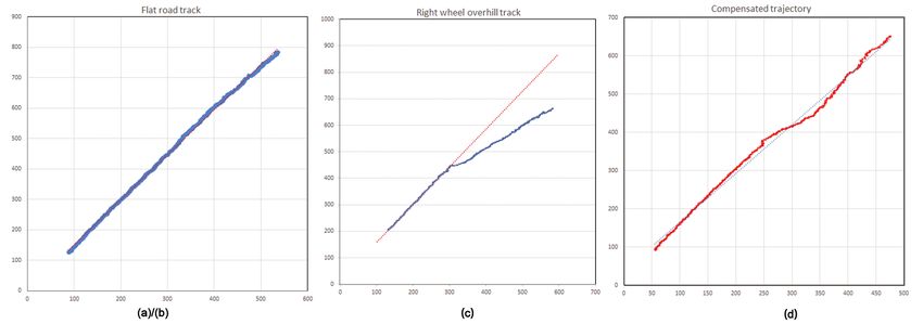
9
10
11
12   2    WeiqiangY et al.
13
14   1 Introduction
15
16   Mobile robots, due to their increasing use in various fields such as security
17   surveillance, home surveillance for health and entertainment, research and
18   education[2–4], are attracting increasing attention and advances in the past
19   decade due to their home services and applications.
20       Since the smart lawnmower can break the problem down into several more
21   manageable parts,these parts can be solved individually and then combined
22   to solve the overall problem. A complex nonlinear model can be broken down
23   into a set of locally linearized models and then interpolated to get the overall
24   system.This approach is called Multi-Model-Approach (MMA), also known as
25   T-S modeling[1].The interpolation of all individual models is carried out using
26   fuzzy logic.
27       Recently,the use and control of differences between current detection and
28
     linearization models as data feedback to enable intelligent lawnmowers to per-
29
     form certain tasks has attracted a great deal of interest from researchers in
30
31   related fields.If you compare the results of performing tasks without feed-
32   back with those with feedback,it becomes clear that the overall performance
33   is more efficient and secure with feedback.The smart lawnmower’s bias is a
34   combination of studying currents and syncing.It has received a lot of attention
35   from autonomous systems and control groups. Cooperative coordination can
36   be described as assigning the left and right motors to follow a predetermined
37   path of travel while receiving useful information through their sensors and
38   maintaining the prescribed direction. The path trajectory can be coordinates
39   that the intelligent lawnmower must follow, or a specified driving area within a
40   certain limit (see[5] and references therein). Dead reckoning has already been
41   extended to the case of a mobile robot moving on uneven terrain. It provides
42   information on positioning for mobile robots by directly calculating parameters
43   such as position, speed and orientation[6].
44       In [10], the author proposed a mechanism structure for the mobile robot
45   with the advantage of adaptability using hybrid modes with active wheels.
46
     There is a lot of research and literature on smart lawnmowers.B.Patra et al.
47
     from the Indian Institute of Engineering Science, Technology and Technology
48
49   examined in detail the problem of tracking a smart two-wheel drive lawnmower.
50   By studying the kinematics, dynamics and the linear feedback controller, some
51   basic, e.g. straight and semicircular trajectories (continuous and discontinu-
52   ous) were simulated. The real trajectories largely correspond to the simulation
53   results through experimental results, while the ideal path of the intelligent
54   mower also depends on the actuator[7], and various control techniques that
55   are applied to the model are briefly described. Dynamics modeling, simulation
56   and system identification are also examined in other publications. a simple
57   proportional-integral-summation controller is given in Jithu et al[8] for use.
58   Posture control techniques using an observer are described in Xu et al[9].
59       The proprietary sensors measure values within the system (robot) such
60   as battery power, wheel position, joint angle, motor speed, etc.These sensors
61   can be encoders, potentiometers, gyroscopes, compasses, etc. Huiwen Guo and
62
63
64
65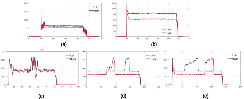
9
10
11
12                                                             WeiqiangY et al.      3
13
14   Xinyu Wu from the Shenzhen Institute of Advanced Technology of the Chinese
15   Academy of Sciences proposed a visual localization system that is important
16   for lawn map creation and area coverage. They used stable light compensa-
17   tion and aimed the camera mounted on the smart mower towards the ground
18   to extract and match feature points through pairs of frames to locate the
19   smart mower[10].Huiwen Guo and Xinyu Wu et al. used the MATLAB2010b
20   software in their computer for data processing and the program ran in the
21   MATLAB2010b environment. Experiments proved the feasibility of their posi-
22   tioning system, but the amount of data processed by the computer was large.
23
     Some of the main challenges are navigation and path planning, localization
24
     and obstacle avoidance.
25
26       The application of fuzzy theory to control systems is widespread in the
27   literature. Mobile robotics has been in development for many years, but for
28   location technology, technology remains a hot research topic for scientists.
29   While there are many different positioning methods and the sensors used, there
30   are two broad types of positioning - absolute and relative. Absolute positioning
31   relies on external sensors etc. to infer the position of the mobile robot directly
32   in the location map, while relative positioning techniques rely on the position
33   in the previous or initial moment to create the final projection[10]. Common
34   absolute positioning techniques include satellite positioning, ultrasonic posi-
35   tioning, bluetooth positioning, visual positioning, and UWB ultra-broadband
36   positioning. The most important relative positioning technique is dead reckon-
37   ing. Initially, some authors tried to represent nonlinear systems by piecewise
38   linear approximations[11] using local models and switching. A few years later,
39   Takagi et al.
40       Navigation is a fundamental problem in robotics and other important tech-
41
     nologies. Linear path control or linear control is an important topic in practical
42
     application and research. The relative position, posture and speed of an intel-
43
44   ligent lawnmower must be controlled to avoid sagging when the travel path
45   changes from the task demands. The most common route method is to use
46   a compass to determine if a distraction is occurring, but compass stability is
47   susceptible to environmental and magnetic influences. Leader-follower control
48   strategies have been widely explored, including various techniques such as PID
49   control methods[12], and a non-linear controller has been developed by com-
50   bining nested saturation with consensus control to achieve a smart lawnmower
51   that can safely track the direction of travel change in a targeted manner.
52       The mobile robot determines its path in real time in order to avoid
53   randomly moving obstacles[13]. Other intelligent algorithms that have been
54   studied by researchers that are used by mobile robots to navigate differ-
55   ent environments are DE (the Differential Evolution) algorithm[14, 15], HS
56   (the Harmony Search) algorithm[16], BA(the Bat-Algorithm)[17] and IWO
57   (Invasive Weed Optimization)[18]. To ensure accuracy in the localization,
58   sensors and an effective positioning system must be considered.Object posi-
59
     tioning [20], robotics and AR(augmented reality) tracking[19] are of interest
60
     in recent literature. Each of these sensors is used in robots, mobile devices
61
62
63
64
65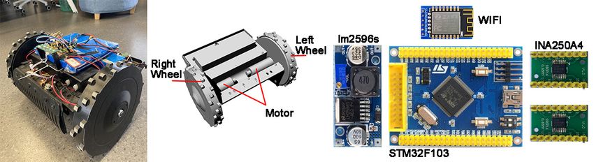
9
10
11
12 4 WeiqiangY et al.
13
14 and navigation systems[20–22]. The only advantages of using these sensors
15 are to calculate the position and orientation of a device and/or object.
16 Magnetometer is another sensor that is used to calculate heading angle by
17 sensing the earth’s magnetic field. They are combined with pose determination
18 technologies[14],Other methods used to determine indoor localization include
19 Infrared, Wi-Fi, UWB(Ultra-Wideband), Bluetooth, Wide Local Area Net-
20 workWLAN (), fingerprinting etc.,[23–26]. However, these methods have their
21 shortcomings, so it is necessary to combine two or more schemes in order to
22 get accurate results. It does have the advantage of better performance in terms
23
of accuracy, but it is more expensive and more complex to calculate[27].
24
In this post a full dynamic model is used and the difference between the
25
26 current detection and linearization models is used to get a linear model. The
27 difference between the obtained linear model and the actual nonlinear system
28 at a certain operating point is added to the linear system, and satisfactory
29 results are obtained by taking into account disturbances in the design of the
30 controller.
31
32 2 Test platform construction
33
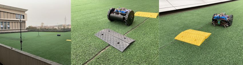
34 The robot system is conceived by placing it on a mobile platform(Figture1).
35 The author uses the self-made lawnmower system as a basis to test the theory.
36 Among the main components: 24V lithium battery, two DC motors, rack; one
37 STM32F103 main control, two current detection modules(INA250A4), Wi-Fi
38 module, through which the experimental platform is built to obtain current
39 data.
40
41
42
43
44
45
46
47
48
49 Fig. 1 Main structure:two 35W motors,a 24V power supply,a control panel
50
51
52
53 3 Methods
54
55 The one-way drive wheels going uphill and downhill cause a change in current
56 and yaw of the mower at the same time, and there is a regular trend.Therefore,
57 there is a theoretical basis for compensating for the motor Hall data based on
58 the current fluctuation. However, it should also be noted that the following
59 derivation (Sections 3, 4, 5) greatly simplifies the actual situation and the
60 actual situation is much more complex than the theoretical derivation. The
61
main ones include the following:
62
63
64
65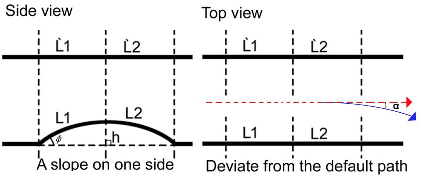
9
10
11
12                                                           WeiqiangY et al.      5
13
14       (1) The motor power factor differs with different loads and is not a linear
15   number.
16       (2) Slope surfaces, in addition to the angle, length parameters influence
17   the course and are often accompanied by wheel slip, which can change the
18   coefficient of friction.
19       (3) The efficiency of the mower’s power transmission structure varies with
20   different power outputs.
21       (4) Duty cycle control motors whose real-time currents are high-frequency
22   changing data, which makes it difficult to acquire accurate RMS(Rate Mono-
23
     tonic Scheduling) values.
24
25
26
27
28   Fig. 2 Flow chart for detecting current fluctuations
29
30
31       For the above reasons, it is difficult to build an accurate mathematical
32   model between current change and yaw angle, so we use a fuzzy control scheme.
33   Using the current change value and the current change duration as inputs,
34   we create a two-dimensional fuzzy controller, obtain empirical data based on
35   several tests(Figture2), obtain effective control parameters and finally output
36   suitable Hall compensation data.
37
38
39
     4 Theoretical background of intelligent lawn
40     mower control
41
42   A very important part of the path control of the intelligent mower is to control
43   the car so that it goes straight. It is common practice to set up a serial PID
44   control system for the left and right wheels, using heading angle as input and
45   motor Hall data as feedback, with the following control flow diagram(Figture3).
46
47
48
49
50
51
52
53
54
55
56
57
     Fig. 3 Two-wheel mower PID control flow chart
58
59
60       This solution makes it possible to control the mower so that it drives in a
61   straight line on flat grass. In complex terrain, such as However, for example,
62
63
64
65
9
10
11
12 6 WeiqiangY et al.
13
14
15
16
17
18
19
20
21
22
23
24
25
26
27
28 Fig. 4 Flow chart for PID control (with fuzzy controller compensation) of a two-wheeled
lawn mower
29
30
31 on uneven surfaces and slippery surfaces in the rain, the mower will yaw due
32 to the error between the Hall feedback data and the actual distance the wheels
33 have traveled at that time. In this case, an additional compensation scheme
34 must be added to the basic control scheme.
35 A common compensation option is to add additional sensors to the mower
36 to aid in course keeping. One of these is the addition of an electronic compass or
37 motion sensor that forms the EMU’s inertial navigation unit. Another option
38 is to add cameras based on machine vision, again with algorithms or mileage
39 and heading data. However, both approaches have certain limitations. One
40 of them is the increasing costs, including the cost of adding and upgrading
41 hardware, and the increasing R & D costs due to the difficulty of developing
42
software algorithms. The second are the limitations of the use case; Electronic
43
compasses are sensitive to the environment and susceptible to magnetic field
44
45 interference, motion sensors usually need to be calibrated, and cameras have
46 an unstable image in outdoor sunlight[28, 29].
47 To address this problem, we tried to devise a new course hold control
48 scheme based on traditional fuzzy PID control theory by modifying the rela-
49 tionship between the fuzzy controller and the PID controller(Figture4). First
50 and foremost, a fuzzy controller is added to the above-mentioned serial level
51 PID controller loop for Hall data. This fuzzy controller takes the current fluc-
52 tuation of the mower’s drive wheel motor as input and outputs various Hall
53 compensation data for various amounts of current fluctuation(Figture4).
54
55
56
5 The effect of grassland terrain on mower
57 deflection
58
59 In grassy terrain, two wheels driving over a slope at the same time do not
60 cause yaw. It is above all the difference in gradient between the left and right
61 wheels when driving over the slope that causes the mower to deviate from its
62
63
64
659
10
11
12 WeiqiangY et al. 7
13
14 original direction of travel. This leads us to an analysis of the situation on an
15 uphill bike:
16
17
18
19
20
21
22
23
24
25
26
27
28
29 Fig. 5 Schematic diagram of single wheel slope) of a two-wheeled lawn mower
30
31
As can be seen from the diagram(Figture5), the distance traveled by the
32
33 two wheels is different and the difference determines the yaw angle since it is
34 a single wheel crossing the ramp.
35 There are the following relationships:
36
37 ∆L = L1 ∗ (1 − cosΦ) (1)
38
39 α = ∆L/R (2)
40
The combination of the above two equations gives:
41
42
43
44 α = L1 ∗ (1 − cosΦ)/R (3)
45
46 The vehicle’s yaw angle α, the length of the ramp L1, θ is the angle between
47 the ramp and the ground, and R is the wheelbase of two wheels of the vehicle.
48 According to formula (3), the longer the longer the slope length, the larger the
49 angle between the slope and the ground and the more likely it is that the car
50 will yaw.
51
52
53
6 The effect of grassy terrain on motor current
54 As mentioned above, the main influence on yaw in grassy terrain is the differ-
55
ence in slope between the two wheels, so here we analyze the influence of slope
56
areas on the current of the drive wheel motors(Figture6).
57
58 Since the speed of the trolley motor is controlled by a PID speed loop,
59 the speed can be adjusted in an instant, so it can be viewed as a constant
60 uphill speed. The engine output at this point is equal to gravity. There is the
61
62
63
64
659
10
11
12 8 WeiqiangY et al.
13
14
15
16
17
18
19
20
21
22
23
24
25
26 Fig. 6 Analysis of forces on drive wheels uphill
27
28
following relationship:
29
30
31 P =U ∗I ∗η =F ∗V =M ∗ω (4)
32
33
34 Ff = m ∗ g ∗ cosΦ (5)
35
36 F = Ff (6)
37
The combination of the above 3 equations gives:
38
39
40 I = m ∗ g ∗ v ∗ sinΦ/(U ∗ η) (7)
41
42 Where: m is the mass of the trolley, v is the linear speed of the trolley
43 wheels, U is the motor drive voltage, I is the motor drive current, η the motor
44 efficiency and θ the angle. is between the slope and the ground. From the above
45 equation it can be concluded that: the larger the slope angle, the larger the
46 motor current; the longer the slope, the longer the duration of the high current.
47
48
49
7 Discusion
50 Before the effectiveness of the fuzzy control could be tested, a tool had to be
51 introduced that could localize the position of the trolley in real time and thus
52 visually monitor the trolley course offset. The wireless location system UWB
53
(accuracy ± 5cm) was chosen here.
54
55
56 7.1 Experimental site set-up
57 This time several iterations of the experiment were used to count the effect of
58 the fuzzy control compensation. To ensure consistent conditions for multiple
59
experiments, the experimental site was set up as follows(Figture7).
60
61
62
63
64
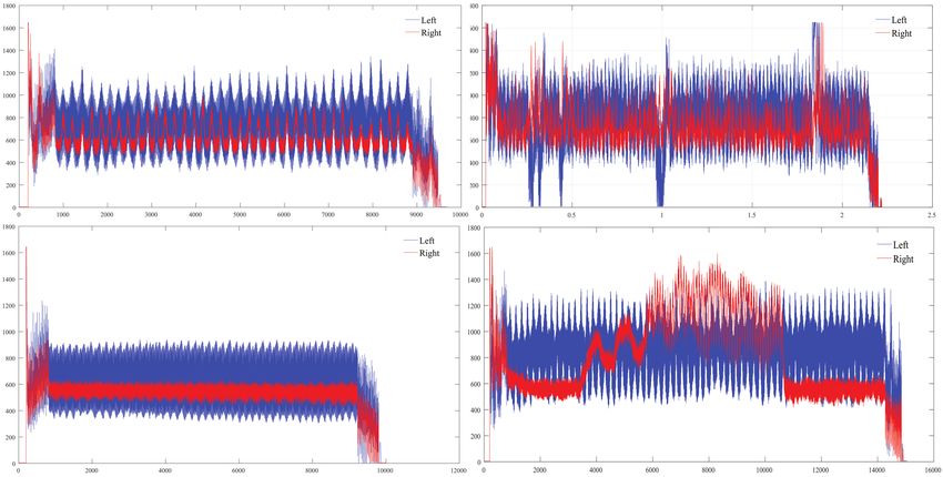
659 10 11 12 WeiqiangY et al. 9 13 14 (1) Design the guide groove of the trolley at the starting position to ensure 15 that the trolley starts in the same direction every time, the road conditions 16 are the same after repeated experiments. 17 (2) Arrange and add the UWB-3D positioning system to the Trolley UWB 18 tags added, which can provide real-time feedback on the position of the trolley. 19 20 21 22 23 24 25 26 27 28 Fig. 7 Scene photos 29 30 31 32 7.2 Experimental data pre-processing 33 34 The focus is on processing motor detection currents using PWM controlled 35 motors with high frequency vibration data for current values as shown in the 36 following figure(Figture8). 37 38 39 40 41 42 43 44 45 46 47 48 49 50 51 52 Fig. 8 Real-time sampling of raw data from motor circuits 53 54 55 The data vibrations are too large and too frequent to be used as input 56 data for fuzzy control, so preprocessing methods must be included. A current 57 maximum is used here instead of the real-time value of the circuit. This is 58 achieved by using a time window in the algorithm in which a maximum value 59 is taken within each window period, which ensures that the maximum value 60 of the current is taken when the window is larger than the current oscillation 61 62 63 64 65
9
10
11
12   10      WeiqiangY et al.
13
14   period. At the same time, the cycle time is as short as possible and yet in real
15   time.
16                                Ff = m ∗ g ∗ cosΦ                               (8)
17
18                                           X
                                             n

19                                    It =         (It + 0.5 ∗ W )                              (9)
20                                           t=0
21      Imax current maximum,It current real time,It ,I(t 1) are time window val-
22   ues, 0.5*W is error value compensation. (Cycle-specific values) The current
23   data after processing with this method are as follows:
24
25
26
27
28
29
30
31
32
33
34
35
36
     Fig. 9 Current data after pre-processing,(a) Current when the motor is idling,(b) Normal
37
     plane driving current conditions, (c) current variation for simultaneous uphill driving, (d)(e)
38   current variation for non-simultaneous uphill driving
39
40
41      The above diagrams(Figture9) show the motor current values after the
42   maximum value and the test conditions are wheel idling and real grass driving
43   with different applied resistances.The amplitude of the current data in the
44   graph is already very small and is very clearly reflected in the ramp resistance.It
45   can therefore be used as an input for the fuzzy control.
46
47   7.3 Experimental Analysis
48
49   The first set of experiments, (a)Trajectory orientation test without the fuzzy
50   controller. The trolley control algorithm does not include a fuzzy controller,
51   so the trolley starts along the guide slot, goes straight for a distance, passes a
52   small manually designed ramp, and then moves on to reach a position to reach
53   the end. The UWB position data of the entire process is recorded in real time,
54   that is the trajectory of the car.The above experiment was repeated 10 times,
55   and the trajectory data were obtained 10 times and plotted as follows.
56       (b) Trajectory orientation test with the addition of a fuzzy controller. The
57   fuzzy controller was added to the trolley control algorithm and the other condi-
58
     tions were exactly the same as in (a) experiment.The experiment was repeated
59
     10 times and the trajectory data was obtained 10 times. The trajectory data
60
61   without fuzzy control and the trajectory data with fuzzy control essentially lie
62   on a smooth surface.
63
64
65
9
10
11
12 WeiqiangY et al. 11
13
14
15
16
17
18
19
20
21
22
23
Fig. 10 Experimentally identical trajectory data (a,b) without fuzzy controller(Group1),(c)
24 Trajectory data without fuzzy controller,(d) Trajectory data for adding fuzzy con-
25 trollers(Group2)
26
27
28 The second series of tests(Figure10(c)(d)), the half bump test. In order to
29 avoid coincidence and also to better debug the fuzzy control parameters, the
30 experiment was repeated with a different ramp and the above experiment was
31 repeated.
32
33 7.4 Experimental results
34
35 From the above comparison tests it can be concluded that after adding the
36 fuzzy controller to compensate for the Hall data, a better course correction
37 effect is achieved.
38
39 8 CONCLUSION
40
41 In this paper, a one-sided control strategy for uneven road conditions is
42 designed. The novelty of our approach is to establish a physical relationship
43 between the differences between the left and right current sensing and lin-
44 earization models and then to use the fuzzy inference engine structure of the
45 incremental adaptive fuzzy PID optimizer which controller gains are achieved
46 through LQR optimization in order to stabilize the system and get the desired
47 response. The leader-follower method is then used to provide control for a pair
48
of left and right motors. Different cases are tested to get the desired path.
49
Regardless of the different definitions given, sensor fusion is the integration of
50
51 information from multiple sources in order to improve the accuracy and qual-
52 ity of the content, also with the aim of reducing costs. It is observed that the
53 new linearization method and the proposed fuzzy control give a good track-
54 ing response and the results obtained are actually tested to get good results,
55 allowing a new way of thinking for controlling the course stability of the path.
56 The shortcoming of this work is that the realistic conditions prevent the test
57 site from digging a pit and thus cannot be tested for concave surfaces, but sim-
58 ilar results can theoretically be derived from the test results on raised surfaces
59 and the next work plan has to be considered as test on concave surfaces.
60
61
62
63
64
659
10
11
12 12 WeiqiangY et al.
13
14 9 DECLARATIONS
15
16 9.1 Ethics approval and consent to participate
17
Not applicable.
18
19
20 9.2 Conflict of interest
21 No potential conflict of interest was reported by the authors.
22
23
24 9.3 Dataset to be available
25 All data generated or analysed during this study are included in this published
26 article.
27
28
29 9.4 Consent for publication
30 Not applicable.
31
32
9.5 Funding
33
34 Not applicable
35
36 9.6 Authors’ contributions
37
38 Weiqiang Ying analyzed and visualized the data and wrote the manuscript,
39 Cheng Kuang analyzed and interpreted the antenna data, Lingyan Zhang
40 collates data and writes the first draft, Cheng Yao analyzed the data, and
41 proofread and edited, Fangtian Ying analyzed the data, Shijian Luo proofread
42 and edited.All authors read and approved the final manuscript.
43
44 9.7 Acknowledge
45
46 The authors acknowledge Computer Aided Product Innovation Design Engi-
47 neering Centre, Ministry of Education, for providing some of the experimental
48 data and helpful discussion and suggestions.
49
50 9.8 Authors’ information
51
52 Weiqiang Ying, study in electrical and control engineering for the PhD at Zhe-
53 jiang University in 2019.and he joined the Ministry of Education of Computer
54 Aided Product Innovation Design Engineering Centre.His research interests
55 include sliding mode control,motion control,and signal processing.
56 Cheng Kuang,Engineer at the Computer Aided Product Innovation Design
57 Engineering Centre, Ministry of Education. Mainly engaged in research in the
58 field of information product design and human-computer interaction
59 Lingyan Zhang,Information Product Design, School of Software, Zhejiang
60 University. Mainly engaged in research in the field of information product
61
design, human-computer interaction, children’s health and learning.
62
63
64
659
10
11
12 WeiqiangY et al. 13
13
14 Cheng Yao,Instructor of Information Product Design, School of Software,
15 Zhejiang University. He is the deputy director of the Computer-Aided Product
16 Innovation Design Engineering Centre of the Ministry of Education and a
17 member of the International Computer Society (ACM). Mainly engaged in
18 research in information product design, technology design, human-computer
19 interaction, industrial design, digital art and design, etc.
20 Fantian Ying,Professor, Zhejiang University,Deputy Director of Zhejiang
21 Province Service Robot Key Laboratory,mainly engaged in research in the field
22 of industrial design and integrated product innovation design.
23
Shijian Luo,Professor, Zhejiang University, Ph. Research interests in Indus-
24
trial design, user experience and product innovation design, service design,
25
26 ergonomics and human-computer interaction design.
27
28 Appendix A Relevant data and information
29
30 https://github.com/laringying88/Planning-the-yaw-correction-trajectory
31
32 References
33
34 [1] Takagi, M. T.and Sugeno: Fuzzy identification of systems and its appli-
35 cation to modeling and control (1985)
36
37 [2] Kumar, G. A.and Hancke, Phala, K.S.: Air quality monitoring system
38 based on iso/iec/ieee 21451 standards. IEEE Sensors Journal 16(12),
39 5037–5045 (2016)
40
41 [3] Mester, G.: Motion control of wheeled mobile robots modeling of the
42 wheeled mobile robots (2006)
43
44 [4] Hancke, G.P., Markantonakis, K.E. K.and Mayes: Security challenges for
45 user-oriented rfid applications within the “internet of things”. Journal of
46 Internet Technology 11(3), 7 (2010)
47
48 [5] Patra, S. B.and Nandy: Lawn mower trajectory tracking by wheeled
49 mobile robot: Its consequences. In: International Conference on Electron-
50 ics, pp. 1–7 (2017)
51
52 [6] Jin-Xia, Y.U., Cai, Z.X., Duan, Z.H., Zou, X.B.: Design of dead reck-
53 oning system for mobile robot. Journal of Central South University of
54 Technology 13(005), 542–547 (2006)
55
56 [7] Rong, X., ümit Özgüner: Sliding mode control of a class of underactuated
57 systems. Automatica 44(1), 233–241 (2008)
58
59 [8] Jithu, G., Jayasree, P.R.: Quadrotor modelling and control. In: 2016
60 International Conference on Electrical, Electronics, and Optimization
61 Techniques (ICEEOT) (2016)
62
63
64
659
10
11
12 14 WeiqiangY et al.
13
14 [9] Rubio, F., Valero, F., Llopis-Albert, C.: A review of mobile robots: Con-
15 cepts, methods, theoretical framework, and applications. International
16 Journal of Advanced Robotic Systems 16(2), 172988141983959 (2019)
17
18 [10] Guo, H., Wu, X., Fu, R., Wei, F.: Robust localization system for an
19 autonomous mower. In: IEEE International Conference on Robotics &
20 Biomimetics (2016)
21
22 [11] Endo, G., Hirose, S.: Study on roller-walker (multi-mode steering control
23 and self-contained locomotion). In: Proceedings 2000 ICRA. Millennium
24 Conference. IEEE International Conference on Robotics and Automation.
25 Symposia Proceedings (Cat. No.00CH37065) (2002)
26
27 [12] Choi, I.S., Choi, J.S.: Leader-follower formation control using pid con-
28 troller. In: International Conference on Intelligent Robotics & Applica-
29 tions (2012)
30
31 [13] Aenugu, V., Woo, P.Y.: Mobile robot path planning with randomly mov-
32 ing obstacles and goal. International Journal of Intelligent Systems &
33 Applications 4(2) (2012)
34
35 [14] Bird, J., Arden, D.: Indoor navigation with foot-mounted strapdown
36 inertial navigation and magnetic sensors [emerging opportunities for
37 localization and tracking]. Wireless Communications IEEE 18(2), 28–35
38
(2011)
39
40 [15] Parhi, D.R., Kundu, S.: Navigational control of underwater mobile robot
41
using dynamic differential evolution approach. Proceedings of the Insti-
42
tution of Mechanical Engineers, Part M: Journal of Engineering for the
43
44 Maritime Environment (2016)
45
[16] Kundu, S., Parhi, D.R.: Navigation of underwater robot based on dynam-
46
47 ically adaptive harmony search algorithm. Memetic Computing 8(2),
48 125–146 (2016)
49
50 [17] Wang, G.G., Chu, H.C.E., Mirjalili, S.: Three-dimensional path plan-
51 ning for ucav using an improved bat algorithm. Aerospace Science and
52 Technology 49(FEB.), 231–238 (2016)
53
54 [18] Sengupta, A., Chakraborti, T., Konar, A., Nagar, A.: Energy efficient
55 trajectory planning by a robot arm using invasive weed optimization
56 technique. In: Nature & Biologically Inspired Computing (2011)
57
58 [19] Kumar, K., Varghese, A., Reddy, P.K., Narendra, N., Balamuralidhar,
59 P.: An improved tracking using imu and vision fusion for mobile aug-
60 mented reality applications. International Journal of Multimedia & Its
61 Applications 6(5) (2014)
62
63
64
659
10
11
12 WeiqiangY et al. 15
13
14 [20] Erdem, A.T., Ercan, A.O.: Fusing inertial sensor data in an extended
15 kalman filter for 3d camera tracking. IEEE Transactions on Image
16 Processing 24(2), 538–548 (2015)
17
18 [21] Azuma, R.T.: A survey of augmented reality. Presence: Teleoperators and
19 Virtual Environments 6(4), 355–385 (1997)
20
21 [22] Benser, E.T.: Trends in inertial sensors and applications. In: 2015
22 IEEE International Symposium on Inertial Sensors and Systems (ISISS)
23 Proceedings (2015)
24
25 [23] Nasir, A.K., Hille, C., Roth, H.: Data fusion of stereo vision and gyro-
26 scope for estimation of indoor mobile robot orientation. Ifac Proceedings
27 Volumes 45(4), 163–168 (2012)
28
29 [24] Sibai, F.N., Trigui, H., Zanini, P.C., Al-Odail, A.R.: Evaluation of indoor
30 mobile robot localization techniques. In: International Conference on
31 Computer Systems & Industrial Informatics (2012)
32
33 [25] Santosh, S., Jae-Young, P.: Practical fingerprinting localization for indoor
34 positioning system by using beacons. Journal of Sensors,2017,(2017-12-31)
35 2017, 1–16 (2017)
36
37 [26] Silva, B.J., Hancke, G.P.: Practical challenges of ir-uwb based ranging
38 in harsh industrial environments. In: IEEE International Conference on
39 Industrial Informatics, pp. 618–623 (2015)
40
41 [27] Yang, Y., Meng, X., Gao, M.: Vision system of mobile robot combining
42 binocular and depth cameras. Journal of Sensors 2017, 1–11 (2017)
43
44 [28] Coito, F., Eleutério, A., Valtchev, S.: Tracking a mobile robot position
45 using vision and inertial sensor. In: Doctoral Conference on Computing,
46 Electrical and Industrial Systems (2014)
47
48 [29] Hol, J.D., SchöN, T.B., Luinge, H., Slycke, P.J., Gustafsson, F.: Robust
49 real-time tracking by fusing measurements from inertial and vision
50
sensors. Journal of Real-Time Image Processing 2(2-3), 149–160 (2007)
51
52
53
54
55
56
57
58
59
60
61
62
63
64
65You can also read