Review of Advancement in Variable Valve Actuation of Internal Combustion Engines - applied sciences
←
→
Page content transcription
If your browser does not render page correctly, please read the page content below
applied
           sciences
Review
Review of Advancement in Variable Valve Actuation
of Internal Combustion Engines
Zheng Lou 1, *       and Guoming Zhu 2
 1    LGD Technology, LLC, 11200 Fellows Creek Drive, Plymouth, MI 48170, USA
 2    Mechanical Engineering, Michigan State University, East Lansing, MI 48824, USA; zhug@egr.msu.edu
 *    Correspondence: gongda.lou@gmail.com

 Received: 16 December 2019; Accepted: 22 January 2020; Published: 11 February 2020

 Abstract: The increasing concerns of air pollution and energy usage led to the electrification of the
 vehicle powertrain system in recent years. On the other hand, internal combustion engines were
 the dominant vehicle power source for more than a century, and they will continue to be used in
 most vehicles for decades to come; thus, it is necessary to employ advanced technologies to replace
 traditional mechanical systems with mechatronic systems to meet the ever-increasing demand of
 continuously improving engine efficiency with reduced emissions, where engine intake and the
 exhaust valve system represent key subsystems that affect the engine combustion efficiency and
 emissions. This paper reviews variable engine valve systems, including hydraulic and electrical
 variable valve timing systems, hydraulic multistep lift systems, continuously variable lift and timing
 valve systems, lost-motion systems, and electro-magnetic, electro-hydraulic, and electro-pneumatic
 variable valve actuation systems.

 Keywords: engine valve systems; continuously variable valve systems; engine valve system control;
 combustion optimization

1. Introduction
      With growing concerns on energy security and global warming, there are global efforts to develop
more efficient vehicles with lower regulated emissions, including hybrid electrical vehicles, electrical
vehicles, and fuel cell vehicles. Hybrid electrical vehicles became a significant part of vehicle production
because of their overall efficiency, and they still pose a significant cost penalty, resulting in a stagnant
market penetration of 3.2% and 2.7% in 2013 and 2018, respectively, in the United States (US), for
example [1]. Electrical vehicles reached a market penetration of 1.3% in the US in 2018 [1], still
limited by high cost and concerns on well-to-wheel CO2 emissions, charging speed, driving range,
battery safety, and battery recycling issues. Fuel cell vehicles offer truly low overall emissions with
driving range and fueling time comparable to vehicles powered by internal combustion engines.
Hydrogen [2], the favorable fuel for fuel cells, can be generated from diverse sources, including natural
gas, nuclear, coal, and renewable sources such as solar, wind, biomass, hydro, and geothermal sources.
The development of fuel cell vehicles [3] is still in its infancy because of issues in technology maturity,
cost, and performance, with only a few thousands of pilot vehicles on the road worldwide.
      Internal combustion engines are believed to remain as a major part of vehicle powertrains in
the foreseeable future, either standing alone or being part of highly electrified powertrains such as
hybrid electrical vehicles, plug-in hybrid vehicles, and range extender vehicles, unless there is a major
technology breakthrough in battery and/or fuel cell technology. For these reasons, it is imperative to
continue advancement in more efficient and less polluting internal combustion engines.

Appl. Sci. 2020, 10, 1216; doi:10.3390/app10041216                              www.mdpi.com/journal/applsci
The combustion in an internal combustion engine involves three key components: in-cylinder
fuel, air, and ignition. In gasoline engines, the fuel injection process evolved from a pure mechanical
process such as via a carburetor to an electronically controlled process such as via port fuel injection
Appl. Sci.recently
or the 2020, 10, 1216
adopted direction injection (see Figure 1). Spark ignition via a spark plug is completely 2 of 20
electronically controlled for spark energy and timing. With its gaseous state, low density, and, thus,
large volume, the electronic control of air exchange was a slow evolution process, from variable valve
1.1. Combustion and Need for Electronic Control of Gas Exchange
time (VVT) to more sophisticated systems such as discrete variable valve lift (DVVL), continuous
The valve
variable combustion in an internal
lift (CVVL), cam-based combustion engine
variable valve involves(VVA),
actuation three key
andcomponents:
camless VVA,in-cylinder
which are
fuel, air, and ignition. In gasoline engines, the fuel injection process evolved
reviewed later in this article. There were also efforts to develop camless VVA to have complete from a pure mechanical
process
electronicsuch as viaofa the
control carburetor to an electronically
air exchange process, which controlled
is a majorprocess
enablersuch as via portcombustion
for advanced fuel injection or
such
the recently adopted
as homogeneous direction
charge injectionignition
compression (see Figure
(HCCI)1). Spark ignition
to improve via afuel
engine spark plug is completely
economy and reduce
electronically
emissions [4–7]. controlled
To improvefor spark
engineenergy and timing.
fuel economy, With downsizing
engine its gaseous state, low density,
techniques and, thus,
are widely used
large
with volume,
the help the electronic control
of turbochargers. of air
In this exchange
case, the VVT,was a slow
VVL, evolution
or VVA systemprocess,
is ablefrom variableengine
to improve valve
time
system(VVT) to more
transient sophisticated systems such as discrete variable valve lift (DVVL), continuous
responses.
variable
In diesel engines, fuelcam-based
valve lift (CVVL), variablefrom
injection evolved valve actuation
pure (VVA),
mechanical and camless
pumping VVA, which
and injection are
systems
reviewed later infuel
to common-rail thisinjection
article. There were also efforts
via electronically to develop
controlled camlessand
fuel pressure VVAinjectors.
to have Note
complete
that
electronic control of the air exchange process, which is a major enabler for advanced
injection timing directly controls the ignition because of the compression ignition. There is less combustion such
as homogeneous
demand charge compression
or development on controllingignition (HCCI) toinimprove
gas exchange engine
traditional fuelengines
diesel economy and reduce
because of its
emissions
compression [4–7]. To improve
ignition engine
and lean fuel economy,
combustion engine
process. downsizing
More techniques
sophisticate are widely
air charge used with
management is
the help of turbochargers. In this case, the VVT, VVL, or VVA system is able
needed for more advanced combustions such as the Miller cycle and PCCI. However, this review is to improve engine system
transient
limited toresponses.
valve systems for gasoline engines.
Figure 1. More
Figure 1. More electronic
electronic control
control of
of inputs
inputs into
into gasoline
gasolineengine
enginecombustion.
combustion.
In diesel engines, fuel injection evolved from pure mechanical pumping and injection systems to
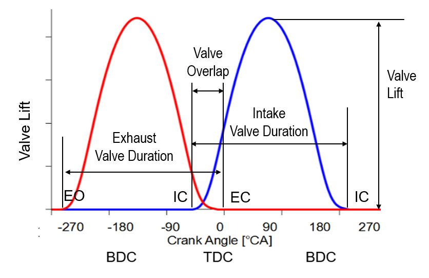
1.2. Valve Lift, Valve Timing, and Valve Duration
common-rail fuel injection via electronically controlled fuel pressure and injectors. Note that injection
timing The main function
directly controls of thean engine because
ignition valve actuation system is to ignition.
of the compression control the gas exchange
There is less demandinto and or
out of a combustion chamber via intake and exhaust valves, respectively.
development on controlling gas exchange in traditional diesel engines because of its compression The associated valve lift or
travel isand
ignition typically illustrated in
lean combustion a valveMore
process. timing diagram (see
sophisticate Figuremanagement
air charge 2 for an example), is needed where valve
for more
timing, valve
advanced lift, and valve
combustions such as duration
the Miller are cycle
defined.
and A valveHowever,
PCCI. lift profile
this describes
review isthe valveto
limited liftvalve
as a
function of camshaft
systems for gasoline engines. angle between its opening and closing. The opening and closing points define
the valve timing in the crank angle domain and, thus, the relationship between the lift profile and the
1.2.
rest Valve
of theLift, Valvecomponents
engine Timing, and Valve Duration
and events such as the piston movement and ignition. Valve lift is
oftenThe
optimized for minimal
main function pumping
of an engine loss.
valve Often, intake
actuation systemand exhaust
is to controlvalve
the gas liftsexchange
are the same,
into andbutout
the
diameter of the intake valve is larger than the exhaust one to ensure that
of a combustion chamber via intake and exhaust valves, respectively. The associated valve lift or travel fresh air can be easily
charged
is typically into the cylinder.
illustrated in a Note
valvethat variable
timing diagramvalve liftFigure
(see has the potential
2 for of throttling
an example), wherethe cylinder
valve timing, by
reducing
valve lift, the
andintake
valve valve lift to
duration arereduce
defined.theA pumping
valve liftlosses associated
profile describeswith the conventional
the valve throttle.
lift as a function of
However, this requires very close control of lift to match changes in engine
camshaft angle between its opening and closing. The opening and closing points define the valve speed and load conditions,
which in
timing is yet
the to be fully
crank angleproven.
domainThe and,overlap
thus, thebetween the intake
relationship valvethe
between opening andand
lift profile the the
exhaust
rest ofvalve
the
closing is an important secondary parameter that has a major impact on
engine components and events such as the piston movement and ignition. Valve lift is often optimized combustion efficiency. The
for minimal pumping loss. Often, intake and exhaust valve lifts are the same, but the diameter of
the intake valve is larger than the exhaust one to ensure that fresh air can be easily charged into the
cylinder. Note that variable valve lift has the potential of throttling the cylinder by reducing theAppl. Sci. 2020, 10, 1216 3 of 20
Appl. Sci. 2020, 10, x FOR PEER REVIEW 3 of 19
area under a lift profile represents the capacity for gas exchange. For the purpose of classifying valve
intake valve lift to reduce the pumping losses associated with the conventional throttle. However, this
actuation systems, the following definitions are provided:
requires very close control of lift to match changes in engine speed and load conditions, which is yet
•to beValve
fullylift
proven.
refers toThe
the overlap between
amplitude, thethe
especially intake valve of
peak value, opening
the valve and
lift the exhaust valve closing is
profile.
•an important
Valve timing refers to parameter
secondary the phase shift
thatinhas
crank angleimpact
a major domainon of combustion
the valve lift efficiency.
profile, especially
The areatheunder
valve
a liftopening
profile and closing events,
represents such asfor
the capacity EO,gas
EC,exchange.
IO, and IC.For the purpose of classifying valve actuation
•systems,
Valvethe
duration refersdefinitions
following to the duration
are when the valve is kept open, i.e., the span between the valve opening
provided:
and closing events.
• Valve lift refers to the amplitude, especially the peak value, of the valve lift profile.
Modern
• engines
Valve timingare oftentoequipped
refers the phasewith
shiftmultiple
in crank intake and exhaust
angle domain of thevalves, for profile,
valve lift example, two intake
especially the
and two exhaust valves. The valve lift, timing, and duration
valve opening and closing events, such as EO, EC, IO, and IC. can be optimized for each individual
valve (for example, using VVA technology) to optimize in-cylinder mixing.
• Valve duration refers to the duration when the valve is kept open, i.e., the span between the valve
opening and closing events.
Figure 2. Regular valve timing diagram for naturally aspirated engines, defining valve lift, timing,
Figure 2. Regular valve timing diagram for naturally aspirated engines, defining valve lift, timing,
and duration.
and duration.
Modern engines are often equipped with multiple intake and exhaust valves, for example,
1.3.
twoClassification
intake and twoof Valve Actuation
exhaust Systems
valves. The valve lift, timing, and duration can be optimized for each
individual valve (for example, using VVA technology) to optimize in-cylinder mixing.
Valve actuation systems are firstly classified into two large groups: cam-driven and camless
systems. A cam-driven
1.3. Classification system
of Valve utilizes
Actuation cam lobes to actuate the valve lift, while a camless system does
Systems
not include any cam mechanism and varies the valve lift using hydraulic, electro-magnetic, or
Valve actuation
pneumatic actuation to systems
provideare firstly classified
flexibility in control.into two actuation
Valve large groups: cam-driven
systems are further andclassified
camless
systems. A cam-driven system utilizes
based on the valve parameters being controlled. cam lobes to actuate the valve lift, while a camless system
doesCamless
not include any cam
systems mechanism
generally and varies
offer more controlthe valve liftand
flexibility using hydraulic,
capability, butelectro-magnetic,
they are yet to be or
pneumatic actuation to provide flexibility in control. Valve actuation systems
implemented in production because of technical difficulties and commercial issues. For this reason, are further classified
based
this on the
review valvecommercialized
covers parameters being controlled.
cam-based systems and only some development work in camless
Camless
systems. systems generally offer more control flexibility and capability, but they are yet to
be implemented in production because of technical difficulties and commercial issues. For this
reason,
1.3.1. this review
Cam-Based covers
Valve commercialized
Actuation Systems cam-based systems and only some development work in
camless systems.
A cam-based valvetrain system is based upon the traditional cam-system to drive the engine
intake and exhaustValve
1.3.1. Cam-Based valves with limited
Actuation control over valve timing and/or lift, and it is now widely
Systems
adopted in many new production engines. Cam-based systems include the following:
A cam-based valvetrain system is based upon the traditional cam-system to drive the engine
•intake
Variable valve valves
and exhaust timing:withOnlylimited
the valve timing
control overis valve
independently controlled
timing and/or while
lift, and it isthe
nowvalve lift
widely
and duration
adopted in many newremain the same.engines.
production The VVT systems are
Cam-based also called
systems camthe
include (orfollowing:
camshaft) phasers. VVT
systems are further classified into hydraulic (HVVT), mechanical (MVVT), and electrical (EVVT)
• types
Variable
basedvalve
on timing: Only thecam
their respective valve timing actuator
phasing is independently
designs.controlled while theVVT
Many production valvesystems
lift and
duration
are HVVTs, remain
usingthe same. known
a device The VVT as asystems
variatorarethatalso calledcontinuous
allows cam (or camshaft)
adjustment phasers. VVT
of the camAppl. Sci. 2020, 10, 1216 4 of 20
systems are further classified into hydraulic (HVVT), mechanical (MVVT), and electrical (EVVT)
types based on their respective cam phasing actuator designs. Many production VVT systems are
HVVTs, using a device known as a variator that allows continuous adjustment of the cam timing,
and EVVTs are getting popular for improving system response time at low temperature or engine
start-up. However, the duration and lift cannot be adjusted.
• Variable valve duration (VVD): Only the valve duration is independently controlled.
• Variable valve lift (VVL): Only the valve lift is independently controlled. VVL systems further
include discrete VVL (DVVL) and continuous VVL (CVVL) designs. A DVVL system includes
a cam profile switching mechanism to activate one of two or three cam profiles or lobes, and a CVVL
system includes a mechanism capable of continuous variation of the life profiles. In most, if not all,
VVL systems, the lobes and mechanisms are designed such that the valve duration increases with
the valve lift, which is a fixed relationship and not an independent control of the valve duration,
although it serves the needs of a normal combustion. These VVL systems by themselves are,
therefore, not classified as VVT, VVD, or VVA systems.
• Cam-Based Variable Valve Actuation (VVA): Cam-based VVA systems include (1) the VVL +
VVT type, which is a combination of VVL (either DVVL or CVVL) and VVT, and (2) the lost-motion
type (LMVVA).
Major cam-based valve actuation systems in production engines are listed in Table 1. Some of
them are discussed in more detail in the later sections.
Table 1. Major cam-based valve actuation systems in production engines.
Introd. Year,
Classification Company System Ind. Timing Ind. Lift Ind. Duration
Comments & Refs
HVVT Nissan VTC/NVCS 2-stage 1987
HVVT Toyota VVT-i Cont, Int 1996
HVVT Mazda S-VT Variable, Int 1998
HVVT Ford Ti-VCT 2-stage, Both 2011
1980, 1st VVT,
HVVT Alfa Romeo VCT 2-stage, Int
piston, [8]
HVVT BMW Single VANOS 2-stage & Cont, Int 1992, [9]
HVVT BMW Double VANOS Cont, Both 1996, [9]
HVVT Ford VCT 2-stage, Int
HVVT GM DCVCP Cont, Both
HVVT Hyundai CVVT Cont, Both
HVVT Hyundai VTVT Variable, Both
HVVT Daihatsu DVVT Cont, Int
HVVT Ducati DVT Cont, Both
HVVT Nissan CVVTCS/CVTC Cont
HVVT Subaru AVCS VVT
HVVT Toyota Dual VVT-i Cont, Both
HVVT Toyota VVT 2-stage
1992, 1st Cont VVT,
MVVT Porsche VarioCam Cont, Int
[7,9]
2007, electric Int,
EVVT Toyota VVT-iE Cont, Both
hydraulic Exh
1993, eccentric
VVD MG Rover VVC Cont, Int
mechanism
2019, eccentric
VVD Hyundai CVVD Cont, Int
mechanism
2- & 3-lobe,
DVVL Honda VTEC 1989, [10]
IntAppl. Sci. 2020, 10, 1216 5 of 20
Table 1. Cont.
Introd. Year,
Classification Company System Ind. Timing Ind. Lift Ind. Duration
Comments & Refs
DVVL Audi AVS 2-lobe, Both 2006, [11]
DVVL Subaru i-AVLS 2-lobe 2007, [12]
DVVL Proton CPS 2-lobe, Int 2016, [13]
2017, motor cycle
DVVL Yamaha VVA 2-lobe
appl, [14]
DVVL +
Mitsubishi MIVEC VVT, Both 2-lobe, Int 1992, [15]
VVT
DVVL + VVL/VVL +
Nissan VVT 2-lobe, Both 1997, [16]
VVT VVT
DVVL +
Porsche VarioCam Plus VVT 2-lobe, Int 1999, [4,17]
VVT
DVVL +
Toyota VVTL-i/VVT-iL Cont 2-lobe 1999, [18]
VVT
DVVL +
Honda i-VTEC Cont, Int 2-lobe, Int 2001, [19]
VVT
DVVL +
Audi AVS Cont, Int 2-lobe, Int 2006, [11]
VVT
CVVL Hyundai CVVL CVVL 2012, [20]
CVVL +
Great Wall CVVL + VVT Cont, Both CVVL 2018, [21]
VVT
CVVL +
BMW Valvetronic Cont, Both CVVL, Int 2001, [22]
VVT
CVVL + BMW and
VTi Cont, Ink CVVL, Int 2002, [23]
VVT PSA
CVVL +
Nissan VVEL + CVTC Cont CVVL 2007, [24,25]
VVT
CVVL +
Toyota Valvematic Cont, Int CVVL 2014, [26]
VVT
LMVVL FCA MultiAir Cont Cont 2009, [27,28]
Notes: Int = intake, Exh = exhaust, Both = both intake and exhaust, Cont = continuous.
1.3.2. Camless Valve Actuation Systems
Without the constraint from the cam mechanism, a camless system is capable of adjusting valve
timing, duration, and lift independently to achieve more desired target levels that can be varied
cycle-by-cycle. It also provides independent control of engine valves for each cylinder. For example, it
is able to provide asymmetric opening for two intake valves for one cylinder, resulting in improved
charge air and fuel mixing. It can also perform cylinder deactivation under low load conditions. It,
thus, offers more control with greater benefits than conventional cam-based valve system. Camless
systems include the following:
• Opposed solenoid electro-magnetic (or electromechanical) camless VVA (EMVVA) [29–34];
• Electro-hydraulic camless VVA (EHVVA) [35–37];
• Electro-pneumatic camless VVA (EPVVA) [38,39];
• Rotary motor EMVVA, also called intelligent valve actuation (IVA) system by Camcon [33,34].
Camless systems are a key technical enabler for other advanced engine technologies, such as air
hybrid vehicles [40], HCCI [41], and high-efficiency diesel engines [42].
In the subsequent sections, various valve actuation systems are grouped and reviewed based on
the valve actuation control parameters and structures.
2. Variable Valve Timing (VVT) System
The VVT technology was first applied to production engines by Alfa Romeo in 1980, and they are
now widely used in most modern engines worldwide as shown in Table 1.Appl. Sci. 2020, 10, 1216 6 of 20
VVT systems were initially stand-alone systems for timing control, and gradually they were
integrated with variable lift mechanisms to become part of a cam-based VVA system, i.e., VVL + VVT.
They are often applied to intake valves only. Their control evolved from two-stage, i.e., two discrete
positions, in the early days to continuous control (“Cont” in Table 1) in more recent engines.
2.1. Hydraulic VVT (HVVT)
An HVVT system includes a hydraulically actuated cam phaser or variator, the design of which
evolved over the last 40 years.
The 1980 Alfa Romeo Spider 2.0 L had the first VVT system, which was an HVVT on the inlet
camshaft. The design comes from a patented design (US Patent 4,231,330) by Alfa Romeo engineer
Giampaolo Garcea [43]. The cam phaser is a cylinder containing a pressure chamber and a piston with
helical splines. Alfa Romeo calls it mechanical VVT because of the helical splines, and it is classified as
hydraulic VVT because of the hydraulic piston. Under oil pressure via a solenoid valve, the piston
rotates slightly due to the helical splines and advances the inlet valve timing by 25◦ to increase engine
valve overlap, which happens between 1500 and 2000 rpm and over 5000 rpm. Otherwise, the valve
timing remains in its natural state.
Most phasers of the later HVVT systems use a rotary vane hydraulic motor, which is actuated by
pressurized oil controlled by a solenoid valve. The cam phaser is operated either in two settings or, as
in most of the more recent systems, continuously.
The BMW single VANOS system, when first introduced in 1992 on the BMW M50 engine, controlled
the timing of the intake camshaft to one of two discrete positions. In 1998, infinitely variable single
VANOS was introduced on the BMW M62 V8 engine. The double VANOS system, which appeared on
the S50B32 engine in 1996, continuously adjusts the timing of the intake and exhaust camshafts [44].
The maximum range of phase timing relative to the sprocket is typically 60◦ [45].
In operation, the hydraulic VVT system can be vulnerable because of oil pressure fluctuation, oil
quality, viscosity, and contamination. There is also a case where the phaser does not get enough oil
because of a wear-induced leakage in the lubrication system [46]. At low temperatures, the system may
not have adequate response time because of high oil viscosity, and the hydraulic VVT system cannot
be activated and has to remain at its default lock position such that the cold-start performance and
emissions cannot be improved [47]. For example, the camshaft phasing speed of the hydraulic VVT
drops to about half of that of the electrical VVT and almost to zero when the operating temperature
drops from 90 ◦ C to 40 ◦ C and −10 ◦ C, respectively. For an engine cold start at −7 ◦ C, the HC emissions
are reduced by about one-third when replacing a hydraulic VVT with an electrical VVT.
2.2. Mechanical VVT (MVVT)
Porsche developed VarioCam, a mechanical VVT first used on the 1992 3.0 L engine in the Porsche
968 [1,8] It varies the timing of intake valves by adjusting the tension on the timing chain connecting
the intake and exhaust camshafts. This mechanical design was not kept in a later version of VarioCam
Plus, which uses a rotary vane hydraulic phaser as most HVVT systems do [1,4].
2.3. Electrical VVT (EVVT)
The issues associated with HVVT systems discussed above led to the development of EVVT
systems, which was also made possible by recent advances in permanent magnetic motor technology
and dramatically reduced motor drive cost. Toyota variable valve timing—intelligent electric (VVT-iE),
for example, is a variation of dual VVT-i, by replacing the hydraulic cam phaser with an electric
cam phaser for the intake camshaft timing [47]. The exhaust camshaft timing is still controlled using
a hydraulic cam phaser. This technology was first introduced on the 2007MY Lexus LS 460 as a 1UR
engine [18]. In operation, the electric motor in the cam phaser spins with the intake camshaft, running
at the same speed to maintain camshaft timing. To advance or retard the camshaft timing, the actuator
motor rotates slightly faster or slower, respectively, than the camshaft speed. The speed differenceAppl. Sci. 2020, 10, 1216 7 of 20
between the actuator motor and camshaft timing is used to operate a mechanism that varies the
camshaft timing.
The performance of an EVVT is less dependent on engine oil temperature and pressure [47], thus
providing better control precision and improving engine performance over a wider operational range.
The control accuracy and fast response of a VVT system is more critical for advanced combustion such
as HCCI, especially for the combustion mode transition control between spark ignition (SI) and HCCI
combustion, where the engine cam timing needs to follow a desired trajectory to accurately control the
engine charge and recompression process, as articulated by Ren and Zhu [48].
3. Variable Valve Duration (VVD) System
In 1993, MG Rover developed a 1.4 L K-series engine with a variable valve control (VVC) system,
which was the first production continuous VVD (CVVD) system. It is based on an eccentric rotating
disc to drive the inlet valves of every two cylinders. Since eccentric shape creates nonlinear rotation,
the opening period of the valves can be varied by controlling the eccentric position of the disc. The basic
concept was developed by Mitchell and it was published and patented back in 1973 [49]. In this design,
the control is purely to vary the valve duration, with the valve lift fixed, thus differing from various
DVVL or CVVL designs.
In 2019, Hyundai Motor Group announced that it developed CVVD technology to be in the
Smartstream G1.6 T-GDi for future Hyundai and Kia vehicles [50–52]. Their design is based on
a concept disclosed by Kim et al. [53]. It also involves utilization of some pins and slots to create
eccentric alignment. With the duration variation in accordance to driving conditions, it is able to
deliver a 4% increase in performance along with a 5% boost in fuel efficiency. The CVVD technology
also helps reduce tailpipe emissions by 12% [50].
4. Discrete VVL (DVVL) and Associated VVA Systems
A discrete VVL (DVVL) system includes a cam profile switching mechanism to activate one of two
or three cam profiles or lobes, and it becomes a cam-based VVA (or DVVL + VVT) system when a VVT
mechanism is further incorporated. The applications of DVVL and DVVL + VVT systems include, but
are not limited to, Honda, Audi, Subaru, Proton, Yamaha, Mitsubishi, Nissan, Porsche, Toyota, Honda,
and Audi, as shown in Table 1.
In 1989, Honda launched, in Integra, the world’s first commercial DVVL system in a motor vehicle
engine called the variable valve timing and lift electronic control (VTEC) system [10,19,54]. VTEC uses
two (or occasionally three) intake camshaft profiles, switched via hydraulically actuated rocker arm
locking pins. In the system, the timing variation is fixed in the cam profiles and not independent of the
lift variation. Honda then launched, in 2001, a cam-based VVA system called intelligent VTEC (i-VTEC)
in high-output DOHC four-cylinder engines by adding continuous intake cam phasing (timing) to the
traditional VTEC. VTEC controls are still limited to distinct low- and high-RPM profiles, but the intake
camshaft is now capable of advancing between 25◦ and 50◦ , depending upon engine configuration [55].
In 1992, Mitsubishi launched the world’s first cam-based VVA system, a DVVL + VVT system
called the Mitsubishi innovative valve timing electronic control system (MIVEC). It has low-lift and
high-lift cam profiles for low-speed and high-speed engine modes, respectively, which are switched
via a locking pin mechanism. The low-lift cams and rocker arms, used to drive separate intake valves,
are situated on two sides of a centrally located high-lift cam. Each intake valve is operated by a low-lift
cam and rocker arm, while a T-lever between them engages the high-lift cam [15]. The VVT-i system
from Toyota has a similar switching mechanism [18].
In 1999, Toyota launched the variable valve timing and lift intelligent system (VVTL-i or VVT-iL).
The Toyota VVTL-i concept, including its a lift variation system via rocker arm locking pins, is similar
to the Honda i-VTEC concept. Each cam has two lobes, one designed for lower-speed operation and
another designed for high-speed operation, with higher lift and longer duration.Appl. Sci. 2020, 10, 1216 8 of 20
In 1999, Porsche launched its VarioCam Plus, a DVVL + VVT system on the intake side.
The two-lobe valve-lift function is performed by electro-hydraulically controlled switchable tappets.
Each of these 12 tappets consists of concentric lifters which can be locked together by a pin. The inner
lifter and the outer ring element are actuated by a small cam lobe and a pair of larger-profile lobes,
respectively. The timing of each valve is seamlessly varied by an electro-hydraulic rotary vane cam
phaser [1,4]
In 2006, Audi launched, in the 1.8 L TFSI engine, the Audi valve lift system (AVS) [11]. It uses
sliding electro-magnetic sleeves on the camshaft to vary the lift of the valves in two stages depending
on load and engine speed. The system, thus, increases torque while also reducing fuel consumption.
Two versions of the AVS system are available: (1) in the V6 engines in which AVS is used, it acts on
the intake valves, regulating the amount of intake air so that the throttle can remain wide open for
free breathing even at part load, thus reducing throttle losses and improving efficiency; (2) in the
latest-generation 2.0 TFSI, the AVS varies the lift of the exhaust valves, thus reducing flushing losses in
the combustion chamber and ensuring the optimal flow of the exhaust gas to the turbocharger.
5. Continuous VVL (CVVL) and Associated VVA Systems
A continuous VVL (CVVL) system includes a mechanism capable of changing the lift profile
continuously, and it becomes a cam-based VVA (or CVVL + VVT) system when a VVT mechanism is
further incorporated. The applications of the CVVL and CVVL + VVT systems include, but are not
limited to, those by BMW, PSA, Hyundai, Nissan, and Toyota, as shown in Table 1.
In 2001, BMW launched the world’s first CVVL + VVT system, as well as the first CVVL system
called the Valvetronic system [45,56]. The Valvetronic system combines its double VANOS variable
cam timing system for intake and exhaust valves with their CVVL system for lift control of the intake
valve. The CVVL system includes an eccentric shaft moved by an electric stepper motor and the
camshaft, with the camshaft being driven by the VANOS phaser. The valve lift can be varied from
0.18 mm to 9.9 mm. Later, in 2002, PSA Peugeot Citroën and BMW jointly developed a variable valve
lift and timing injection (VTi) engine based on the Valvetronic concept [23].
In 2007, Toyota launched, in the Noah, the Valvematic system, which is essentially a combination
of VVT-i and a continuously variable valve lift (CVVL) mechanism for the intake valve. This system is
functionally similar to and structurally simpler and more compact than BMW Valvetronic. It varies
intake valve lift in the range 0.9 mm to 10.9 mm, with a corresponding or coupled valve opening
duration range of 106◦ to 260◦ in crank angle [26].
In 2007, Nissan launched a cam-based VVA system by combining its continuous variable valve
timing control (CVTC) and variable valve event and lift (VVEL) systems, which are VVT and CVVL
mechanisms, respectively [24,25]. It performs similarly to BMW’s Valvetronic system but with
desmodromic control of the output cam, allowing VVEL to operate at higher engine speeds. The Nissan
VVEL system includes a rocker arm and two types of links that open the intake valves by transferring
the rotational movement of a drive shaft with an eccentric cam to the output cam. The movement of
the output cam is varied by rotating the control shaft with a direct current (DC) stepper motor and
changing the fulcrums of the links.
In 2012, Hyundai launched a CVVL system [20] characterized by its compactness, i.e., no increase
in engine height, using a unique six-linkage mechanism. In 2018, Great Wall became of the first Chinese
OEMs launching a CVVL + VVT system [21].
6. Lost-Motion VVA (LMVVA)
Various lost-motion systems were disclosed in many patents, for example, US 4671221, US 5193494,
US 5839400, US 6053136, US 6553950, US 6918364, US 681476, US 7819100, US 8578901, US 8820276, US
8776738, and US 9625050.
Fiat Powertrain Technologies and Schaeffler Group developed the only mass production systems
branded as MultiAir and UniAir, respectively, which were first launched at the 2009 Geneva MotorAppl. Sci. 2020, 10, 1216 9 of 20
Show in the Alfa Romeo MiTo and were licensed in 2017 to Jaguar Land Rover for its Ingenium
engine family.
In the MultiAir system, a solenoid valve controls the hydraulic pressure in a passageway connecting
the intake valves and the camshaft [27]. The solenoid valve regulates the amount of oil that is pumped
by the cam action either to the valve or a bypass reservoir. When pressurized, the hydraulic line
behaves like a solid body and transmits the lift schedule imparted by intake cam directly to the intake
valve in the full valve lift mode for max power. When the solenoid is disengaged, a spring takes over
valve actuation, losing solid transmission of the motion from the cam in other three modes, which
are the early intake valve closing mode, the late intake valve opening mode, and the multi-lift mode,
thus leading to the name lost motion. This electro-hydraulic link allows independent operation of the
two components, resulting in certain control over the valve lift profiles. A closed solenoid keeps the
hydraulic fluid pressurized, transmitting the intake cam profile to the valve in the normal fashion,
while an open solenoid breaks the effective link between cam and valve, decoupling their profiles [27].
This system is not a full VVA system because the valve timing and duration are not independent
of the lift in each of the three lost-motion modes although one has a choice to choose three different
dependencies, i.e., variability or control flexibility, among these three modes. The intake valve opening
event cannot be shifted ahead or left of that at maximum power, which may be necessary for certain
EGR operations. Also, the intake valve closing event cannot be extended beyond or right of that at
maximum power, which may be necessary for certain Miller cycles.
Jacobs Vehicle Systems Inc. also developed its own version of the lost-motion VVA system, with
emphasis on diesel engine efficiency and after-treatment optimization [57]. It includes the capability of
on-off control of secondary events for IEGR and engine braking, high load capacity for early exhaust
opening and engine braking, and inherent protection against valve-to-piston contact.
More recently, there were efforts by Gongda Power [58] and Shandong University [59] to replace
solenoid valves for individual actuators with motor-driven rotary valves common to a group of
actuators, to achieve more stable and faster time response at low temperature and/or to devise
an alternative hardware, but at the cost of losing independent controllability for individual actuators
within a group. The Gongda Power system [58] uses two motor-driven rotary valves, instead of
just one valve by Shandong University [59], to add control flexibility to achieve the Miller cycle by
enabling much later intake valve closing to reduce pumping loss and lower air temperature. It can also
incorporate a special cam lobe to achieve earlier exhaust valve opening and, thus, compression brake
function for a diesel engine.
7. Electro-Magnetic VVA (EMVVA) Systems
7.1. Opposed Solenoid EMVVA
Most effort in camless VVA system development was devoted to EMVVA, actuated by a pair of
opposed electromagnets and balanced by a pair of compression springs. It is capable of generating
variable valve timing and duration, but with fixed lift operation.
The developers of this technology include Valeo [19,60–62], FEV [30,31,63–65], GM [29], Ford [66],
Visteon [32], BMW [45], TRW [67], Siemens [68], MIT [69], Ibaraki University [70], LGD Technology [71],
Instituto Motori of National Research Council of Italy [72], and Aura System [31].
Valeo acquired the related technologies from FEV, Sagem, and Johnson Control and developed
them to a more mature system, which was marketed as smart valve actuation (SVA) [73] and later as
e-Valve [60,62]. e-Valve claims to have reached the required maturity level for mass production [60].
The key issues and challenges, some of which may remain unresolved at this point, for EMVVAs
in general include the following:
• Seating instability and the resulting noise and valve durability issues due to the highly
nonlinear nature of the electro-magnetic latching force unique to the opposed solenoid design.Appl. Sci. 2020, 10, 1216 10 of 20
Chang et al. [69] incorporated a nonlinear spring or nonlinear mechanical transformer for better
soft seating and/or low holding current.
• Need for an accurate, robust, and durable position sensor for each actuator [62].
• Limited or no capability to achieve a variable lift or low lift profile, necessary for some advanced
combustions. Lou [71] proposed incorporating a hydraulic mechanism for enhanced capability.
• High incremental cost, which is a challenge for camless VVAs. A four-cylinder engine with
electronic actuation on only the intake valves is expected to cost about €300 more to build [62].
• Electrical power consumption. Okada et al. [70] proposed a bias permanent magnet to reduce
energy consumption and a seesaw architecture to improve performance and the fitness.
7.2. Rotary Motor EMVVA
Camcon Technology [33] is developing a camless engine for passenger vehicles based on their
proprietary IVA system, which allows valve lift, timing, and duration to be independently and
continuously controllable.
Different from earlier EMVVA systems using opposed solenoids, IVA employs a four-phase
rotary actuator, i.e., a rotary motor, using a rotor which is extended to provide a separate camshaft
for each individual poppet valve [34]. A desmodromic linkage connects this camshaft to the entirely
conventional valve. The actuator is electronically synchronized with the crankshaft and drives the
rotor through the required angular trajectory in order to provide the selected valve event, which is
enabled via a non-contact absolute rotary encoder to determine the rotor position for each actuator.
Camcon collaborated with Jaguar Land Rover to fit the intake valve IVA onto an Ingenium 2.01
four-cylinder gasoline engine, with favorable test results in power consumption, lift repeatability, noise
level, durability, and fuel economy [34,74].
Further development work is being carried out to achieve capability for higher engine speed
and exhaust valve actuation [34]. Brunel University London is using a single-cylinder version of
IVA technology called single-cylinder intelligent valve technology (SCI) to study future powertrain
concepts and speed up OEM and tier 1 engine development [75]
7.3. Other EMVVAs
There are other kinds of EMVVAs. LaunchPoint Technologies, for example, developed a linear
motor EMVVA, which includes a voice coil actuator, a position sensor, and a nonlinear energy storage
mechanism [76]. The energy storage mechanism can both recover the valve’s kinetic energy, thus
reducing the system energy consumption, and help soft seating at the open and close. The low-power
actuator is used only to catch and release the valve at the beginning or the end of the stroke. It is able
to maintain repeatable performance with 1.63–3.82 ms switch times, 0.01–0.07 m/s seating velocity,
and 1.33–3.15 J energy consumption per switch. No further report is available on the development
since a news post in 2014 [76]. The need of a position sensor for its normal function may present cost
and reliability issues in application.
8. Electro-Hydraulic VVA (EHVVA) Systems
In EHVVA systems, primary actuators are hydraulic actuators, such as a piston-cylinder
mechanism, controlled by electro-hydraulic valves. Compared with an EMVVA, an EHVVA generally
has higher power density but lower efficiency. The hydraulic fluid has high bulk modulus suitable for
snubbing in the valve seating process, and its viscosity is highly sensitive to temperature, becoming
too viscous for proper function at lower temperature. Some major EHVVA systems are listed below,
which are also listed in Table 2 for comparison.
• Sturman Industries developed the hydraulic valve actuation (HVA) system. It includes two digital
two-way pilot valves, a proportional valve, a hydraulic actuator with boost and drive pistons,
and a position sensor necessary for closed-loop lift control [35,77]. The actuator is returned eitherAppl. Sci. 2020, 10, 1216 11 of 20
hydraulically or by a return spring. It offers full control in valve timing, duration, and lift, and
it was used in an experimental 15 L natural gas engine and as universal research modules for
various research programs [78]. Its necessary use of a position sensor may incur high cost and
reliability concerns for mass production.
• Lotus and Eaton jointly developed the active valve train (AVT) system. It includes one digital
three-way pilot valve, one servo valve, one return spring, and a hydraulic actuator integrated with
a position sensor needed for closed-loop lift control [79]. Like Sturman’s HVA, the AVT system
offers full control in valve timing, duration, and lift. It may also have cost and reliability issues
associated with the position sensor.
• AVL and Bosch developed the electro-hydraulic valvetrain system (EHVS) system [80]. It
includes two digital main valves, a hydraulic actuator with a two-stage differential piston drive,
a pilot-controlled variable snubber for seating control, and no return spring. It uses an open-loop
control and, thus, has no need for a position sensor, which offers substantial cost and reliability
benefits but presents concerns in lift calibration and accuracy.
• Gongda Power developed the Gongda-VVA-2 (GD-VVA-2). It includes one digital three-way
pilot valve, one digital three-way main valve, an actuator with one lift-control sleeve, two-step
seating control, open-loop two-step lift control, and no position sensor [81–84]. The two-step
lift control provides robust and accurate position control, which is delineated mechanically by
the lift-control sleeve, without the need for an expensive and unreliable position sensor. It also
has a two-level hydraulic damping mechanism for effective valve seating speed control over
a wider temperature range. The two-step lift control does present certain functional compromise,
which can be compensated for by its infinitely variable timing capability inherent in this and
other EHVVAs. One GD-VV-2 prototype system passed 1000 h of durability testing on a test
bench. There is also a proposal to incorporate some CVVL mechanisms into the base GD-VV-2
design, resulting in a full VVA system, still without the need for a position sensor for each engine
valve [85].
Table 2. Some major electro-hydraulic VVA (EHVVA) systems.
Company System Design Features Pros Cons
Sturman Hydraulic Two digital 2-way pilot valves, Full lift variability High sensor cost and
Valve Actuation a proportional valve, a return reliability concern
(HVA) spring, and closed-loop control
with a position sensor.
Lotus-Eaton Active Valve One digital 3-way pilot valve, one Full lift variability High sensor cost and
Train (AVT) servo valve, one return spring, reliability concern
and a hydraulic actuator
integrated with a position sensor.
AVL-Bosch Electro-hydraulic Two digital main valves, Full lift variability Lift accuracy concern
Valvetrain a hydraulic actuator with and low cost
System (EHVS) a two-stage differential piston
drive and a pilot controlled
variable snubber for seating
control, no return spring,
open-loop control without
a position sensor
Gongda Gongda VVA-2 One digital 3-way pilot valve, one Accurate lift and 2-step lift
Power (GD-VVA-2) digital 3-way main valve, low cost
an actuator with one
lift-control-sleeve, 2-step seating
control, open-loop 2-step lift
control without position sensor.
There are many other studies on EHVVA systems. One major effort is to minimize the energy
consumption by the VVA system itself by using some kind of pendulum mechanism, similar to the
compression spring pendulum used in the EMVVA system. Some examples are as follows:Appl. Sci. 2020, 10, 1216 12 of 20
• Ford developed an EHVVA system that has a unique hydraulic pendulum design, i.e., some
fluid spring pendulum [7,86], which tries to convert the kinetic energy into hydraulic pressure
or potential energy during both the opening and the closing stroke. The system includes
a high-pressure and a lower-pressure switch valve and a couple of check valves, and it requires
close monitoring and feedback on the engine valve position. However, the fluid spring may be
difficult to manage because of the high bulk modulus of a typical hydraulic fluid. Additionally,
the fluid bulk modulus is highly variable under the influence of the entrapped air.
• Gongda Power developed the LGD-VVA-1 system that consists of a two-spring actuation, a bypass
passage, and an electro-hydraulic latch-release mechanism [36,37]. The two-spring pendulum
system is used to provide efficient conversion between the moving mass kinetic energy and the
spring potential energy for reduced energy consumption. Its latch-release mechanism can also
compensate for the lost frictional energy during the pendulum motion. Prototypes of the system
were bench- and engine-tested. This system, at least with its limited prototype design, presents
some challenge in packaging because of its total height, considering adding two springs to the
necessary hydraulic mechanism.
• DaimlerChrysler developed various designs using a two-spring pendulum with a hydraulic
latching (US Patent Nos. 4930464, 5595148, 5765515, 5809950, 6167853, 6491007, and 6601552).
However, the designs do not have an effective latching mechanism that can add energy to
the pendulum to compensate for the frictional loss and cylinder air pressure, and there is no
mechanism to change valve lift.
9. Electro-Pneumatic VVA (EPVVA) Systems
There were several studies and developments in electro-pneumatic VVA (EPVVA) systems [38,
39,87–89]. As a work medium, air in an electro-pneumatic system is better than hydraulic fluid in
an electro-hydraulic system in terms of the insensitivity of its viscosity to the system temperature.
Air leakage also does not impose pollution problem. However, Watson and Wakeman [88] found the
following issues with the pneumatic actuator:
• Noise issues associated with air exhaust, choking, and hard valve seating associated with a pure
pneumatic actuator design.
• Repeatability issues in lift control because of air flexibility.
• Sizing issues, at least for their particular design, due to the peak air pressure limit.
The most serious development of an EPVVA system was carried out by the Swedish company
Freevalve AB, formerly Cargine and a sister company to Koenigsegg Automotive AB, which developed
an EPVVA system branded as Freevalve on an existing SAAB car engine [89,90]. The Freevalve
technology also appeared in the Qoros 1.6 L four-cylinder engine [89,91]. The Freevalve system
includes pneumatic valve actuators for opening, springs for valve closing, and position sensors for
feedback control. An oil damping mechanism must be incorporated, as shown in Reference [38], to help
resolve the seating issue, and the technology is, therefore, also called an electro-hydraulic-pneumatic
actuator [89]. The claimed benefits include up to a 30% increase in horsepower and torque, up to a 30%
improvement in fuel economy, and a 50% reduction in overall emissions, based on a report [90] in 2013.
Ma et al. [38] proposed an adaptive lift control scheme for an early version of the Freevalve
technology to improve the intake valve lift repeatability. A control-oriented electro-pneumatic valve
model was developed and used for adaptive parameter identification, and a closed-loop control
scheme of valve lift was developed, utilizing the identified parameters in real-time. The main control
techniques used in the process include model reference adaptation and the MIT rule [92]. The resulting
maximum steady-state lift errors were less than 0.4 mm at high valve lift and less than 1.3 mm at low
valve lift, which is still not accurate enough for commercial application.Appl. Sci. 2020, 10, 1216 13 of 20
10. Valve Profile Tracking of Camless VVA Systems
In an engine without a camshaft, the accuracy and fidelity of the electronic control of valve profile
are critical to achieve the desired engine performance. The valve profile tracking includes the following
basic control objectives for most camless applications [81]:
1) Valve timing control for optimum combustion phase and valve collision avoidance.
2) Valve lift control.
3) Profile area (integration of valve lift profile over time or crank angle) control for accurate
air exchange.
4) Engine valve soft seating for noise control and extending durability.
As noted by Li et al. [81], the overall valve duration control and the valve transition response
(rising and falling slopes) control studied in literature can be classified into valve timing control and
profile area control, respectively. For traditional cam-based engine valves, the above four properties
are guaranteed by proper design of the cam profile. For camless VVAs, these control objectives can
be achieved either partially or simultaneously, depending on the specific VVA system design and
its application.
Adaptive peak lift control was employed by Levin et al. [93] for an EMVVA and by Ma et al. [94]
for an EPVVA to achieve proper valve lift repeatability.
Feedforward control was used for valve timing control to compensate for the valve-opening or
valve-closing delays for EHVVA and EPVVA by Liao et al. [95] and Ma et al. [38], respectively.
Soft seating control is a challenge for the EMVVA because of nonlinear magnetic force, and
it is one of the most studied subjects in the field. Peterson et al. [96] studied guaranteed valve
response using extreme seeking control. Tai and Tsao [97] used a combination of a feedforward
linear–quadratic regulator and repetitive learning control to reduce cycle-to-cycle variations. These
control designs [96,97] were intended for single or multiple control objectives. Others dealt with the
overall valve profile control as a single tracking problem. Wang and Tsao [98], for example, applied
a combination of model reference control and repetitive control to achieve asymptotic profile tracking.
Eyabi and Washington [99] applied the sliding mode control to achieve repeatable tracking performance
with guaranteed seating velocity. In addition, there were studies associated with the application of
EMVVA systems in the combustion mode transition between SI and HCCI combustions [63], stratified
lean combustion [69], and turbulent jet ignition [64].
For an EHVVA system, Sun and Kuo [100] and Gillella et al. [101] proved the effectiveness of
robust repetitive control and time-varying internal-model-based control, respectively, in tracking the
desired valve profile under both steady-state and transient engine operations.
For the EHVVA system by Lou et al. [84], Li et al. [81] studied the profile tracking problem without
the need for complicated control scheme because of the inherent robust nature of its lift control and
seating-velocity control. However, the valve timing and profile area controls are still challenging
because of the nonlinear and time-varying nature of the hydraulic system, including nonlinear flow
dynamics and temperature-sensitive fluid viscosity [83,102]. A receding horizon linear–quadratic
tracking (LQT) controller was designed along with a Kalman optimal state estimation, which was
proven to be effective through both steady-state and transient validations.
11. Summary
As a summary, the engine valve system with active control can be mainly divided into three
groups: variable valve timing (VVT), variable valve lift (VVL), and camless valve system. The authors
believe that each valve system has its own application domain. For the variable valve timing system,
the trend is to move to electrical VVT systems motivated by reducing engine cold-start emissions
and significant cost reduction of electrical drive systems. VVA systems may be used for engines with
advanced combustion modes such as spark-controlled compression ignition (SpCCI). Among VVA
systems and compared with the combined VVT and VVL systems, the camless systems have higherAppl. Sci. 2020, 10, 1216 14 of 20
cost and less maturity but have the ultimate control flexibility, which is needed as an enabler for more
advanced combustion modes such as HCCI to further improve the engine performance with reduced
emissions. The benefit of different valve technologies with respect to engine fuel economy is not
readily discernable or available because a new engine is typically incorporated with multiple new
technologies; some of them are summarized in Table 3 below, where the baseline is the conventional
cam-based valve system.
Table 3. Fuel economy benefits.
Valve System Type System and Fuel Economy and Other Key Benefits Reference
HVVT General: 3%–5% better FE
HVVT BMW double Vanos: up to 10% better FE [9]
EVVT General: 3%–5% better FE, especially with cold-start tailpipe emission reduction
DVVL Audi AVS system: up to 7% better FE [103]
DVVL GM intake valve lift control (IVLC): up to 4% better FE [104]
DVVL + VVT Honda i-VTEC: 13% better FE [105]
CVVL + VVT BMW Valvetronic: 10% better FE [103]
CVVL + VVT Toyota Valvematic: 6% better FE [106]
LMVVA Fiat MultiAir: 10% better FE [107]
VVL + EVVT General: enabling HCCI and 20% better FE [108]
Camless VVA General: enabling HCCI and 25% better FE [108]
Author Contributions: Conceptualization, Z.L. and G.Z.; methodology, Z.L.; software, N.A.; validation, N.A.;
formal analysis, N.A.; investigation, Z.L. and G.Z.; resources, Z.L. and G.Z.; data curation, N.A.; writing— Z.L.
and G.Z.; writing—review and editing, Z.L. and G.Z.; visualization, Z.L.; supervision, Z.L.; project administration,
N.A.; funding acquisition, N.A. All authors have read and agreed to the published version of the manuscript.
Funding: This research received no external funding.
Conflicts of Interest: The authors declare no conflicts of interest.
Abbreviations
AVCS Active valve control system
AVLS Active valve lift system
AVS Audi valve lift system
AVT Lotus-Eaton active valve train
BMW Bayerische Motoren Werke automotive group
CA Crank angle
CPS Cam profile switching system
CVTC Nissan continuous variable valve timing control
CVVD Continuous VVD
CVVL Continuous VVL
CVVT Continuous VVT
CVVTCS Continuously variable valve timing control system
DCVCP Double continuous variable cam phasing
DOHC double overhead camshaft
DVT Discrete valve timing
DVVL Discrete VVL
DVVT Discrete VVT
EC Exhaust closing
EHVS AVL-Bosch electro-hydraulic valvetrain system
EHVVA Electro-hydraulic VVA
EC Exhaust closing
EGR Exhaust gas recirculation
EO Exhaust opening
EPVVA Electro-pneumatic VVA
EVVT Electrical VVT
FCA Fiat Chrysler AutomobilesAppl. Sci. 2020, 10, 1216 15 of 20
FE Fuel economy
FEV Forschungsgesellschaft für Energietechnik und Verbrennungsmotoren
GD-VVA-2 Gongda VVA-2
GM General Motors
HC Hydrocarbon
HCCI Homogenous charge compression ignition
HVVT Hydraulic VVT
IC Intake closing
IEGR Internal exhaust gas recirculation
IO Intake opening
IVA Camcon intelligent valve actuation
i-VTEC Honda intelligent VTEC
LMVVA Lost-motion VVA
MG Morris Garages
MIT Massachusetts Institute of Technology
MIVEC Mitsubishi innovative valve timing electronic control
MVVT Mechanical VVT
NVCS Nissan valve control system
OEM Original equipment manufacture
PCCI Premixed charge compression ignition
PSA Peugeot Société Anonyme
SpCCI Spark-controlled compression ignition
SVA Valeo smart valve actuation, also e-Valve
TFSI Turbo fuel stratified injection
TRW Thompson Ramo Wooldridge
VANOS German words for variable camshaft timing
VTC Valve timing control
VTEC Honda variable valve timing and lift electronic control
VTVT Variable timing valve train
VVA Variable valve actuation
VVC Variable valve control
VVD Variable valve duration
VVEL Variable valve event and lift
VVL Variable valve lift
VVT Variable valve time
VVT-iE Toyota variable valve timing intelligent electric
VVTL-i or
Toyota variable valve timing and lift intelligent
VVT-iL
References
1. Hybrid-Electric. Plug-in Hybrid-Electric and Electric Vehicle Sales. Available online: https://www.bts.gov/
content/gasoline-hybrid-and-electric-vehicle-sales (accessed on 27 January 2020).
2. Alternative Fuels Data Center. Available online: https://afdc.energy.gov/fuels/hydrogen_basics.html (accessed
on 27 January 2020).
3. US DOE. Fuel Cell Electric Vehicles. Available online: https://afdc.energy.gov/vehicles/fuel_cell.html
(accessed on 3 February 2020).
4. Brüstle, C.; Schwarzenthal, D. VarioCam Plus-A Highlight of the Porsche 911 Turbo Engine. SAE Tech.
Paper 2001. [CrossRef]
5. Duesmann, M. Innovative Valve Train Systems, Spectrum: Technology Highlights and R&D Activities at FEV.
2002, p. 3. Available online: https://www.fev.com/fileadmin/user_upload/Media/Spectrum/en/spectrum19.
pdf (accessed on 27 January 2020).
6. Tai, C.; Tsao, T.; Schörn, N.; Levin, M. Increasing Torque Output from a Turbodiesel with Camless Valvetrain.
SAE Tech. Paper 2002. [CrossRef]You can also read