Sergey Schutsky*, S.V. Korzhov, А.S. Boldyrev Don State Technical University, Rostov-on-Don, 344002, Russia
←
→
Page content transcription
If your browser does not render page correctly, please read the page content below
E3S Web of Conferences 281, 01039 (2021)                                 https://doi.org/10.1051/e3sconf/202128101039
CATPID-2021 Part 1

      Optimization of the steel frame elements
      sections formed by i-beams diagonal expansion
      Sergey Schutsky*, S.V. Korzhov, А.S. Boldyrev
      Don State Technical University, Rostov-on-Don, 344002, Russia

                    Abstract. The article deals with the design of steel frames with the
                    elements of variable stiffness, formed by the I-beam walls dissolution
                    along the diagonal and subsequent welding. The possibility of rolled I-
                    beams with different profiles optimal use along Industry Standard
                    Association of Enterprises and Organizations for Standardization of
                    Ferrous Metallurgy Products 20-93, for the frame pre-fabricated elements
                    is determined. A calculation algorithm for determining the geometric
                    characteristics of a composite section is presented. The analysis of such
                    elements use effectiveness is carried out, using the example of the building
                    frame, designed according to the frame-link scheme of welded single-span
                    frames with variable section elements in accordance with the standard
                    typicals 828 KM.

      1 Introduction
      One of the main and urgent problems of modern engineering and applied research is
      resource conservation, which is of direct practical importance for the construction industry
      and economy of the Rostov region.
          There is currently a decrease in the volume of housing construction, against the
      background of which the industry is recovering at an accelerating pace. The most popular in
      the construction industry are the industrial and warehouse buildings [10].
          Due to the fact that the most common structural scheme of industrial and warehouse
      buildings is a metal frame made of architraves with an appropriate system of horizontal and
      vertical ties, the work considers the optimal options for designing steel frames from I-
      beams of variable stiffness.
          Buildings with variable cross-section frames are produced today in the Russian
      Federation by many factories provided with the equipment for cutting and assembling I-
      beams. The most widespread use is found for single-span frames with the spans from 12 to
      36 m with hinged support of the struts on the foundation and rigid coupling of the girder
      with the extreme struts.
          Domestic and foreign design practice offers the following options for designing such
      frames: 1) use of I-beams with a perforated wall as racks and crossbars; 2) use of I-beams
      with corrugated walls as posts and crossbars; 3) use of I-beams with fluted web as posts and
      crossbars; 4) the use of welded I-beams with a wall of variable height as racks and

      *   Corresponding author: svpike1@rambler.ru

© The Authors, published by EDP Sciences. This is an open access article distributed under the terms of the Creative Commons
Attribution License 4.0 (http://creativecommons.org/licenses/by/4.0/).
E3S Web of Conferences 281, 01039 (2021) https://doi.org/10.1051/e3sconf/202128101039
CATPID-2021 Part 1
crossbars; 5) use as racks and crossbars of frames of rolling I-beams of variable height,
formed from ordinary I-beams by diagonal opening of the walls with subsequent welding.
2 Materials and methods
A frame with the use of frames made of rolled I-beams of variable height, formed by
dissolving and subsequent welding of the walls of ordinary I-beams, was selected as the
research subject.
The main stage in the design of frames from transverse frames of variable cross-section
is the static analysis of structures for the external loads action. In addition to the tasks of
static analysis, at this stage, the search for the effective geometry of frames, optimal
distribution of stiffness, optimization of sections and manufacturability is carried out [2, 11,
12]. To reduce the frame structures mass, a number of the researchers in the field of
designing frames with variable stiffness recommend increasing the bending stiffness of the
sections by increasing their height at the points of action of bending moments with
maximum gradients, for example, in the area of the eaves frame node [1]. This technique
gives a possibility to redistribute the bending moments in the interface zone of the struts
and crossbars of the frame, unloading the frame spans, which makes it possible to reduce
the metal consumption and deformability of these frames.
Studies in the field of I-sections optimal sizes selection [3,4] have established that the
determining factor influencing the bent I-beams efficiency is the height of the section and
the wall flexibility. This work does not consider I-beams, the work of the wall of which
occurs in the supercritical stage, since a stable wall is used in rolling I-beams, the maximum
flexibility of which, as a rule, does not exceed 150 [5].
In frames of variable cross-section, the maximum normal stresses in the chords from the
longitudinal force and bending moment act over sufficiently long sections. When such
frames operate in the elastoplastic stage, plastic deformations can propagate along a
considerable length of the element, which can lead to the collapse of the entire structure.
Therefore, the norms [6] regulate the restrictions on the plastic deformations development
in the frame sections, as a result of which such frames are calculated in the elastic stage. In
particular, this is expressed in the ignorance of the coefficient cx, taken from the Table 1 [6]
depending on the ratios of the areas of the flanges and walls of the calculated I-beams.
Within the framework of this work, it is proposed that such stresses arise only in the eaves
zone of the frame; therefore, it is permissible to take into account the work of I-beams in
the elastoplastic stage in the span sections of variable cross-section frames.
To set the dimensions of this zone in a numerical value, we introduce a parameter that
determines the longitudinal force contribution to the stress-strain state of the frame element.
Under the action of a bending moment M and longitudinal force N in the compressed
flange of the I-beam, stresses arise, equal in sum to steel resistance:
N M
N M Ry , Ry
A W
where W and A define the resistance moment of the considered flange and the total I-
beam area.
From this formula, the required moment of resistance can be expressed:
2E3S Web of Conferences 281, 01039 (2021) https://doi.org/10.1051/e3sconf/202128101039
CATPID-2021 Part 1
M 1 (1)
W
Ry 1 N
A Ry
Introducing M/Ry as WM - the required moment of the section resistance in the absence
of longitudinal force, the expression (1) is written as follows:
1
W WM
N
1
Ry
There is a possibility to express the parameter that determines the fraction of the stress
N
from the longitudinal force from this equation. When this parameter’s value is
Ry
close to 0, it is rational to take into account the section work in the simplified stage.
The optimal section height of the bent I-beam is found according to the well-known
formula [5]:
3
hopt 3 W
2
where λ=h/t is I-beam wall flexibility.
Finite transformations of this formula, including the parameter ψ, in particular, reflected
in the monograph [1], are as follows:
3 WM
hopt 3
2 1
It follows from the formula that the optimal height of the I-beam is increased when the
1
compressive force acts on it in proportion to the parameter 3 . In fact, the
1
compressive longitudinal force leads to a displacement of the neutral axis of the section and
an increase in the height of the compressed zone of the wall, which negatively affects its
local stability.
The studies on the displacement values dependence of the neutral axis [9], make it
possible to conclude that the neutral axis displacement effect is insignificant and for the
parameter ψE3S Web of Conferences 281, 01039 (2021) https://doi.org/10.1051/e3sconf/202128101039
CATPID-2021 Part 1
The assembly of rolled I-beams is performed by complying a longitude vertical joint in
one-sided mechanized way on a flux cushion. It is allowed to perform the above-mentioned
joints in a mechanized way in the environment CO2 one-sided (to a depth of at least half of
the I-beams thickness), with the exception of the areas in the drop apron sections of the
frames, where the vertical joints must be double-sided (at a length of 1000 mm in the frame
racks and 1500 mm in the frames’ crossbars). This requirement imposes restrictions on the
I-beam assortment various positions applicability. The elements to be welded on opposite
sides of the butt joint must have the same wall thickness. According to this requirement, the
possible sections of I-beams are grouped by Industry Standard Association of Enterprises
and Organizations for Standardization of Ferrous Metallurgy Products 20-93, for the pre-
fabricated element design of a frame of variable stiffness with a constant wall thickness
(Table 1).
3 Research results
It is rational to use rolling I-beams located at opposite positions of the group in
designing the pre-fabricated element. As a rule, columnar and wide-flange I-beams have a
more developed width and thickness of the flanges, which allows them to be used in the
compressed zone of a frame element. In a situation in which one rolled profile has a large
flange width, but a smaller flange thickness than another rolled profile from the group, an I-
beam with a larger flange thickness is preferred as an element of the compressed zone, due
to its increased influence on the section resistance moment.
Table 1. The possible sections of I-beams are grouped by Industry Standard Association of
Enterprises and Organizations for Standardization of Ferrous Metallurgy Products 20-93
Cross Section Flange width, Wall
Flange thickness, mm
section height, mm mm thickness, mm
40B2 400,000 200,000 13,000
45B1 446,000 199,000 12,000
30Sh1 294,000 200,000 12,000
8,000
35Sh1 334,000 249,000 11,000
20K2 200,000 200,000 12,000
25K1 246,000 249,000 12,000
45B2 450,000 200,000 14,000
50B2 496,000 199,000 14,000
30Sh2 300,000 201,000 15,000
9,000
35Sh2 340,000 250,000 14,000
25K2 250,000 250,000 14,000
30K1 298,000 299,000 14,000
55B1 543,000 220,000 13,500
9,500
40Sh1 383,000 299,000 12,500
50B3 500,000 200,000 16,000
55B2 547,000 220,000 15,500
10,000
60B1 596,000 199,000 15,000
40Sh2 390,000 300,000 16,000
4E3S Web of Conferences 281, 01039 (2021) https://doi.org/10.1051/e3sconf/202128101039
CATPID-2021 Part 1
25K3 253,000 251,000 15,500
30K2 300,000 300,000 15,000
35K1 342,000 348,000 15,000
60B2 600,000 200,000 17,000
45Sh1 440,000 300,000 18,000
50Sh1 482,000 300,000 11,000 15,000
30K4 304,000 301,000 17,000
40K1 394,000 398,000 18,000
70B1 691,000 260,000 15,500
60Sh1 582,000 300,000 12,000 17,000
35K2 350,000 350,000 19,000
So, with the required wall thickness of an I-beam with a variable cross-section of 8 mm,
it is rational to use an I-beam as a product for designing a belt of a compressed zone 25K2,
for the extended zone 30SH1 or 40B2. In this case, it is necessary to check whether the
selected pair of I-beams will be enough to construct a section of the required height.
As an object of research, the frame of the building, designed according to the web-beam
scheme from welded single-span frames with variable cross-section elements in accordance
with standard cipher solutions 828 KМ, was chosen. Frames with rigid upper nodes and a
flange connection in the fastigium are pivotally supported on the foundation at an elevation
150 mm. The frames are gable, the slope of the crossbars is 10%. In the original project, the
crossbars and posts are obtained by unreeling (along an inclined line) the I-beams 50 B2
and 55 B2 according to GOST 26020-83 for the brands with their subsequent tilting on 1800
and welding. High-strength bolted frame joints М24 of steel 40Х «Select» are used. Frame
span 24m; frame pitch 6m; crossbar top mark +8.145. The frames are equipped with girders
made of rolled profiles, which in the outer spans work according to a two-span scheme with
the support on spacers along the half-timbered posts.
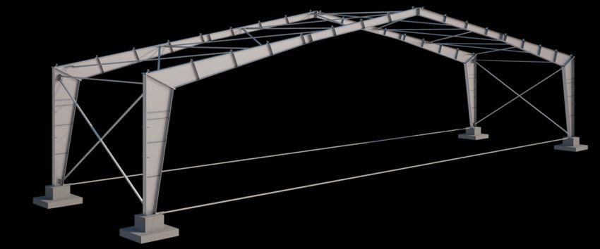
The cross-frame is divided into three starting marks. The central part of the frame
crossbar is made of a variable section beam with a maximum height at the building
fastigium. The part of the frame crossbar adjacent to the cornice unit is made with a
separate pre-fabricated mark with the maximum section height in the area of the cornice
unit. The frame post is made with a separate pre-fabricated mark, the connection with the
crossbar is made by means of a flange connection (Fig. 1).
Fig. 1. Model of a transverse frame made of variable I-beams section.
5E3S Web of Conferences 281, 01039 (2021) https://doi.org/10.1051/e3sconf/202128101039
CATPID-2021 Part 1
Loads from the roofing, snow and wind loads are applied to the transverse frame of the
frame. Calculation of efforts was performed in the SCAD Office software package based on
the finite element method [8].
The preliminary dimensions of finite elements are assigned in accordance with the
standard series used in the frames design of such spans. The foundation support is modeled
hingedly, the girders and pillars are divided into rod finite elements up to 2 m long.
The most optimal placement of the flange connection in the frame girder is located at a
distance of 4 m from the eaves gutter assembly at the zero bending moment point. The
calculation of the frame elements was carried out according to the formulas [1.5] in the
following sequence:
1) Calculation of the initial coefficients taking into account the influence of shear
stresses from the action of shear forces on the beam web stability, taking into
account the stiffeners arrangement:
0 1 M 0
k 0 1.316 Q 3 , ka 0 3
M Ry
2
a Ry
as well as the calculation of a parameter that takes into account the contribution of
stresses from the longitudinal force to the work of the structure:
3 0
N 3
8 M Ry
2
where M, N, Q are design forces in the element, λ0 denotes initial flexibility of the
element, Ry is design steel resistance, а is stiffener spacing.
2) Calculation of the required moment of resistance (according to the formula 41 [6]):
M
WM .
Ry c cx
3) Determination of the initial limiting flexibility of the wall:
6 (1 0,5 )
ц 0 kr
k 0
4 1 12 ( )2
1 0.76 ka 0
where δλ=1 is the coefficient for I-beams with a stable wall, presented in the range of
rolled products.
3) Determination of the optimal section height for I-beams with a stable wall:
3
hopt , mono 3 WM w0
2
4) Section height assignment hw taking into account I-beam optimal cutting, structural
and other requirements. Wall thickness assignment tw, depending on the assigned wall
flexibility.
5) Determining the area of the flanges:
6E3S Web of Conferences 281, 01039 (2021) https://doi.org/10.1051/e3sconf/202128101039
CATPID-2021 Part 1
WM t h 1 3
Compressed flange area: A1ef w w w
(1 ) hw 6 1
WM t h 1 3
Stretched flange area: A1ef w w w
(1 ) hw 6 1
where δw=1 is the coefficient for I-beams with a stable wall, presented in the range of
rolled products.
7) Determination of the calculated thickness and width of the flanges:
Aief Aief
tief f , bief
kr w
tief w
4 Conclusion
The performed calculations showed that the use of different positions of the assortment for
unreeling and subsequent welding made it possible to reduce the variable section element
mass in comparison with the I-beams of the same standard size used in the series. The
difference in metal consumption was 15.7%, which allows us to conclude that the use of the
elements of variable cross-section formed by I-beams diagonal dissolution of various cross-
sections in the construction of industrial frame buildings is a promising direction for
investigation.
References
1. V.V. Katyushin, Buildings with frames made of steel frames of variable cross-section,
Monograph (Publishing house АSV, Moscow, 2018).
2. N.P. Abovskiy, Selected problems in structural mechanics and elasticity theory
(Stroyizdat, Moscow, 1978).
3. B.I. Balyayev, Optimization of cross-sections of beams with chords of rolled tees and a
web of sheet steel. Manufacturing of metal and installation of building structures.
Express information, Minmontajspezstroy, Issue. 4, USSR, Moscow, 1990.
4. Ya.L. Kaplun, Optimization of the assortment of rolled profiles, PhD Thesis summary,
(Science, Moscow, 1971).
5. Central Research Institute of Building Structures named after Kucherenko Gosstroy of
the USSR, A guide to the design of steel structures (Stroyizdat, Moscow, 1989).
6. Building Codes "Steel structures". BC 16.13330.2017. Central Research Institute of
Building Structures named after Kucherenko.
7. V.V. Kuznetsov, Designer handbook, vol. 3 (АSV, Moscow, 1999).
8. А.А. Alyamovskiy, Solid works, Cosmos Works: finite element analysis (DMK,
Moscow, 2004).
9. Yu.V. Sobolyev, Construction and architecture 1, 18-21 (1985).
10. Information on htps: // www.vedomosti.ru /realty /articles /2020/02/16/ 823152-
zhilischnoe-stroitelstvo. Date of access 16.03.2021.
7E3S Web of Conferences 281, 01039 (2021) https://doi.org/10.1051/e3sconf/202128101039
CATPID-2021 Part 1
11. S.V. Skachkov, Solving the problem of optimizing the design parameters of beveling
trusses with T-belts, Lightweight building structures: Collection of scientific papers
(Rostov-on-Don, Rostov State University of Civil Engineering, 1999).
12. А.О. Zaprosyan, Optimization of sections of welded poly-beams, Lightweight building
structures (Collection of scientific papers, Rostov-on-Don, 1993).
8You can also read