Study on retardance due to well-ordered birefringent cylinders in anisotropic scattering media
←
→
Page content transcription
If your browser does not render page correctly, please read the page content below
Study on retardance due to well-
                 ordered birefringent cylinders in
                 anisotropic scattering media

                 Yihong Guo
                 Celong Liu
                 Nan Zeng
                 Honghui He
                 E. Du
                 Yonghong He
                 Hui Ma

Downloaded From: https://www.spiedigitallibrary.org/journals/Journal-of-Biomedical-Optics on 12 Feb 2022
Terms of Use: https://www.spiedigitallibrary.org/terms-of-use
Journal of Biomedical Optics 19(6), 065001 (June 2014)

                Study on retardance due to well-ordered birefringent
                cylinders in anisotropic scattering media
                Yihong Guo,a,b,† Celong Liu,a,b,† Nan Zeng,b Honghui He,b E. Du,a,b Yonghong He,b and Hui Maa,b,*
                a
                 Tsinghua University, Department of Physics, Beijing 100084, China
                b
                 Tsinghua University, Shenzhen Key Laboratory for Minimal Invasive Medical Technologies, Graduate School at Shenzhen,
                Shenzhen 518055, China

                                 Abstract. We report an anisotropic tissue model containing well-ordered birefringent cylinders. Using simula-
                                 tions and experiments, we examined the different polarization features for nonbirefringent and birefringent cyl-
                                 inders and analyzed the influence of the birefringent cylinders on the retardance obtained from Mueller matrix
                                 polar decomposition. For the well-ordered birefringent cylinders, retardance increases linearly with the intrinsic
                                 birefringence and the scattering coefficient. Furthermore, the cylinders with a larger diameter generate more
                                 retardance. Compared with the cylinder-birefringence model, in which birefringent medium exists between
                                 the scatterers, the intrinsic birefringence on the cylinders usually contributes much less to the total retardance.
                                 © The Authors. Published by SPIE under a Creative Commons Attribution 3.0 Unported License. Distribution or reproduction of this work in whole or in
                                 part requires full attribution of the original publication, including its DOI. [DOI: 10.1117/1.JBO.19.6.065001]

                                 Keywords: birefringent cylinder; polarization; Mueller matrix.
                                 Paper 140019RR received Jan. 11, 2014; revised manuscript received May 7, 2014; accepted for publication May 9, 2014; published
                                 online Jun. 5, 2014.

                1       Introduction                                                                   verifying the validity of the new anisotropic tissue model and the
                Most biological tissues are optically anisotropic turbid media,                        Monte Carlo simulation program, we then analyzed the contri-
                containing fibrous microstructures and birefringence optical                           butions of the well-ordered birefringent cylinders to the retard-
                polarization effects.1–3 It is important to mimic and interpret                        ance obtained from Mueller matrix polar decomposition. We
                the structural and optical anisotropies using polarized scattering                     present the comparison of polarization characterization for
                models or phantoms for tissue characterization.4–7 There have                          the birefringent cylinders model and the model of nonbirefrin-
                been many polarized scattering models for biological tissues.8                         gent cylinders with birefringence medium between them. The
                Wang et al. presented a sphere birefringence model, which con-                         study will help us to understand and mimic the polarization
                tains spherical particles randomly suspended in linearly birefrin-                     behavior of photons in complicated tissues and explain the opti-
                gent media.9 He and Yun et al. proposed a sphere-cylinder                              cal anisotropy and characteristic features of tissues based on
                scattering model (SCSM) to characterize the anisotropic scatter-                       polarized photon scattering measurements.
                ing property of fibrous tissues, such as skeletal muscles.10,11
                Furthermore, Du et al. extended the SCSM to the sphere-cylin-
                                                                                                       2     Theory
                der birefringence model (SCBM) by introducing birefringence
                to the medium between scatterers.12 In a previous study, we                            2.1     Polarized Photon Scattering at a
                examined the tissue anisotropy contributed by both the scatter-                                Inhomogeneous Birefringent Cylinder
                ing of cylindrical scatterers and the birefringent media using
                Mueller matrix polar decomposition.13 Lately, it has been                              We have developed a SCSM and a SCBM to describe tissue
                noticed that there exists intrinsic birefringence on intracellular                     anisotropy.11,12 We assumed that the small spheres and infinite
                microtubules, microfilaments, and other fibrous scatterers in tis-                     cylinders are embedded in the medium of linear birefringence.
                sues.14 Recently, in a study on the microstructures of textiles,                       When photons transport through the media, they will be scat-
                Peng et al. proposed a birefringent cylinder scattering model,                         tered by the spherical and cylindrical scatterers. We extended
                in which the textile fibers have different refractive indices in                       the SCBM by replacing the nonbirefringent cylinders with bire-
                the axial and radial directions; a corresponding Monte Carlo                           fringent ones. Peng’s calculation of single scattering for birefrin-
                simulation was also reported for textile fibers randomly distrib-                      gent cylinders is referenced in this paper, but we corrected a
                uted in the xy plane.15                                                                mistake in Eq. (9), and the dielectric coefficient and permeabil-
                    In this article, we extend further the SCBM to include the                         ity are replaced with refractive index, consistent with our pre-
                intrinsic birefringence on the cylindrical scatterers of arbitrary                     vious notations.11
                spatial distributions. We also developed a new Monte Carlo sim-                            We can establish a coordinate system shown below in Fig. 1.
                ulation program to calculate the effects of well-ordered birefrin-                     The refractive index of birefringent cylinders can be written as
                gent fibers to mimic the structure of biological tissues.16 After                      axisymmetric tensors

                                                                                                       n̿ ¼ n2⊥ x^ x^ þn2⊥ y^ y^ þn2jj z^ z^ ;                                    (1)
                *Address all correspondence to: Hui Ma, E-mail: mahui@tsinghua.edu.cn
                †
                    These authors contributed equally to this work.                                    where x^ , y^ , and z^ are the transverse and axial unit vectors.

                Journal of Biomedical Optics                                                  065001-1                                                    June 2014     •   Vol. 19(6)

Downloaded From: https://www.spiedigitallibrary.org/journals/Journal-of-Biomedical-Optics on 12 Feb 2022
Terms of Use: https://www.spiedigitallibrary.org/terms-of-use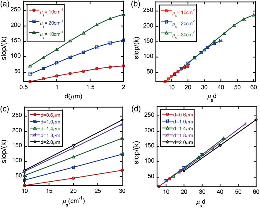
Guo et al.: Study on retardance due to well-ordered birefringent cylinders. . .
8
>
> ð1Þ ð2Þ 0 ð1Þ
>
> Fn ¼ −j sinη ζ H n ðτÞJ n ðξþ Þ þ gn Jn0 ðξþ Þ
>
>
>
< Fð2Þ
2 2
cos ζðn0 −n⊥ Þ ð2Þ
n ¼ ak sin2 ζðn2 −n2 cos2 ζÞ nH n ðτÞJ n ðξ− Þ
⊥
2
0
2 ; (7)
>
>
ð3Þ cos ζðn0 −n⊥ Þ
Fn ¼ ak sin2 ζðn2 −n
ð2Þ
2 cos2 ζÞ nH n ðτÞJ n ðξþ Þ
>
>
>
>
⊥ 0
>
: Fð4Þ 1 ð2Þ 0 ð1Þ 0
n ¼ j η sin ζ H n ðτÞJ n ðξ− Þ − gn J n ðξ− Þ
8
ηn20 χ þ
Fig. 1 Schema of the single light scattering by infinite cylinder. < gð1Þ ð2Þ
n ¼ j kðn2 −n2 cos2 ζÞ · H n ðτÞ
⊥
2
0
; (8)
: gð2Þ n⊥ χ − ð2Þ
n ¼ j ηkðn2 −n2 cos2 ζÞ · H n ðτÞ
⊥ 0
Then, we can write the internal electromagnetic field quan-
tities in the form
rffiffiffiffiffi χ 2 ¼ k2 n2⊥ − cos2 ζ
1 μ0 τ ¼ ak sin ζ þ n2
~ ¼E
E ~ t þ z^ Ez ~ ¼H
H ~ t þ z^ H z . (2) η¼ 20 2
n0 ε0 ξ ¼ a · χ χ 2 ¼ k2 njj2 − n2jj cos2 ζ
− n0 n⊥
n2 (9)
Subscript t expresses the transverse plane, which is n2jj
χ 2þ ¼ k2 njj2 − cos2 ζn2⊥
perpendicular to the z axis. According to these, Maxwell’s equa- × ðnjj ≥ n⊥ Þ 20 ðnjj < n⊥ Þ;
n
tion can be expressed as17,18 χ 2− ¼ k2 n⊥2 − cos2 ζ
0
where ρ and z represent the radial and axial distances in the
D1 ð∇t Þ · H z þ D3 ð∇t Þ · Ez ¼ 0
cylindrical coordinates, a is the radius of the cylinder, n0 is
D2 ð∇t Þ · Ez − D4 ð∇t Þ · H z ¼ 0; (3) the refractive index and η is the wave impedance of the ambient
medium, k ¼ 1∕λ is the wave number, ζ is the angle between the
direction of incident light and the direction of cylinder, and Θ is
where D1 ð∇t Þ, D2 ð∇t Þ, D3 ð∇t Þ, and D4 ð∇t Þ are quadratic func- the azimuth angle of the scattered light on the scattering cone. J n
tions of ∇t , and ∇t is a differentiating operator. By using plane is the Bessel function, H n ð1Þ ¼ Jn þ iY n and H n ð2Þ ¼ J n − iY n ,
wave expansion method, we can solve Eq. (3) to get internal respectively, expressing the first and second kind of Hankel
electromagnetic field quantities Ez and H z , and get E ~ t and function.
~
H t . Using the continuity conditions on the boundary, we can From the above formulas, we can get Mueller matrix
Mðζ; ΘÞ and its elements as follows19
~ s (parallel component E
get scattered field E ~ jjs and perpendicular
0 1
~
component E⊥s ) m11 m12 m13 m41
2 B m21 m22 m23 m42 C
Mðζ; ΘÞ ¼ B C; (10)
sffiffiffiffiffiffiffiffiffiffiffiffiffiffiffiffiffiffiffi πkρ sin3 ζ @ m31 m32 m33 m43 A
Ejjs 1 2 π m41 m42 m43 m44
¼ ej4 e−jkðρ sin ζþz cos ζÞ
E⊥s sin ζ πkρ sin ζ
J1 J4 Ejji 8
× ; (4) > m11 ¼ ðjJ 1 j2 þ jJ2 j2 þ jJ 3 j2 þ jJ4 j2 Þ∕2
J3 J2 E⊥i >
>
>
> m12 ¼ m21 ¼ ðjJ 1 j2 − jJ 2 j2 Þ∕2
>
>
> m13
> ¼ −m31 ¼ RefJ 1 J 4 þ J 2 J3 g
>
>
>
> m ¼ m41 ¼ ImfJ 1 J 4 − J2 J 3 g
8 P P∞ >
< 14
>
> J ¼ ∞ bnI e−inΘ ¼ b0I þ 2 P n¼1 bnI cosðnΘÞ
m22 ¼ ðjJ 1 j2 þ jJ2 j2 − jJ3 j2 − jJ4 j2 Þ∕2
< 1 P−∞ > ¼ −m32 ¼ RefJ 1 J 4 − J2 J 3 g
: (11)
J 2 ¼ P∞ a
−∞ nII e −inΘ ¼ a þ
0IIP 2 ∞ a
n¼1 nII cosðnΘÞ ; >
>
m23
(5) >
>
> J ¼ ∞ a e−inΘ ¼ −2i ∞ a sinðnΘÞ >
> m24 ¼ m42 ¼ ImfJ 1 J 4 þ J 2 J3 g
: 3 P−∞ nI Pn¼1 nI >
>
> ¼ RefJ 1 J 2 þ J3 J4 g
J4 ¼ ∞ −∞ bnII e
−inΘ ¼ −2i ∞ b
n¼1 nII sinðnΘÞ >
>
m33
>
> ¼ −m43 ¼ ImfJ1 J2 þ J 3 J 4 g
> m
: 34
m44 ¼ RefJ 1 J 2 − J 3 J 4 g
8 ð2Þ ð2Þ
>
> a ¼ − 2 Fn J ðξ Þ∕fδ · H n ðτÞg o
> nI n πτ ð1Þ n þ
>
>
> 2 ð2Þ 2.2 Validity for Single Scattering Process
< bnI ¼ nπτη Fn J n ðξ− Þ∕δ − sin ζJn ðτÞ ∕H
>
o
n ðτÞ
2 ð4Þ ð2Þ (6) In the present model, scattering by a birefringent cylinders with
> anII ¼ −sin ζJ n ðτÞ − πτ ηFn J n ðξþ Þ∕δ ∕H n ðτÞ
;
>
>
equal axial and radial refractive indices should be equivalent to a
>
> ð3Þ ð2Þ nonbirefringent cylinders studied in our previous work.11 Hence,
>
> b ¼ 2 Fn J ðξ Þ∕fδ · H n ðτÞg
: nII ð1Þπτ ð4Þ n −ð2Þ ð3Þ we test the validity of the new model and the new simulation
δ ¼ Fn · Fn − Fn · Fn program by checking if the scattering behavior of birefringent
Journal of Biomedical Optics 065001-2 June 2014 • Vol. 19(6)
Downloaded From: https://www.spiedigitallibrary.org/journals/Journal-of-Biomedical-Optics on 12 Feb 2022
Terms of Use: https://www.spiedigitallibrary.org/terms-of-use
Guo et al.: Study on retardance due to well-ordered birefringent cylinders. . .

                cylinders with equal axial and radial refractive indices coincides                     Figure 2 shows that the Mueller matrix elements for single
                with the situation that the cylinder scatters without the                          scattering by a birefringent cylinder are clearly different from
                birefringence.                                                                     those by a nonbirefringent cylinder. To examine the polarization
                    Figure 2 shows the Mueller matrix elements as functions of                     features of fibrous tissue microstructures, contributions by the
                the azimuth angle Θ for a single scattering of a birefringent cyl-                 intrinsic birefringence on the cylinders need to be considered.
                inder with the different axial and radial refractive indices marked
                by solid black line, and a birefringent cylinder with same axial                   3       Samples and Experiments
                and radial refractive indices marked by dotted black line. All are                 For further verification of our Monte Carlo program for birefrin-
                calculated using our newly developed program. The Mueller                          gent cylinders and demonstration of the influence of birefringent
                matrix elements of nonbirefringent cylinder calculated with                        cylinders on polarization measurements, we present the simula-
                our previous program are shown as the red dotted line com-                         tion and experimental results of forward scattering Mueller
                pletely overlapping with the dotted black line,11 which confirms                   matrix of nonbirefringent and birefringent cylinders, respec-
                the validity of the developed program for birefringent cylinders.                  tively. In the experiments, we prepare two samples by winding
                In Fig. 2, Mueller matrix mij except for m11 (i, j ¼ 1; : : : ; 4) are             either well-aligned nonbirefringent glass fibers or birefringent
                all normalized by m11 ½mij ðΦÞ∕m11 ðΦÞ. And m11 is normalized                     silk fibers around small frames.20 The experimental setup has
                by m11 ðΦ ¼ 0°Þ, m11 ðΦÞ∕m11 ðΦ ¼ 0°Þ.                                             been used in a previous study for forward scattering Mueller

                                       Fig. 2 Single scattering Mueller matrix of a birefringent cylinder with the different axial and radial refrac-
                                       tive indices of 1.57 and 1.53 (solid black lines), and a birefringent cylinder (dotted black lines) with the
                                       same axial and radial refractive indices of 1.57. Calculations for a nonbirefringent cylinder with the refrac-
                                       tive index of 1.57 are shown as the red dotted lines, which overlap completely with the dotted black lines.
                                       The incident angle of light is ζ ¼ 45 × deg and the diameter of the cylinder is 1.5 μm. The abscissa is
                                       azimuth 0–180 deg.

                Journal of Biomedical Optics                                              065001-3                                                June 2014   •   Vol. 19(6)

Downloaded From: https://www.spiedigitallibrary.org/journals/Journal-of-Biomedical-Optics on 12 Feb 2022
Terms of Use: https://www.spiedigitallibrary.org/terms-of-use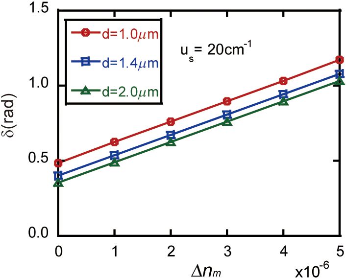
Guo et al.: Study on retardance due to well-ordered birefringent cylinders. . .
matrix measurements.5 Before the experiments, we measured air 4 Results and Discussion
and a polarizer as the standard samples, and the calibration The Mueller matrix can characterize polarization properties of a
errors can be estimated at about 5%.13 sample. There are several other methods to decompose Mueller
Figure 3(a) represents the experimental result for the silk matrix; in a previous work,13 we used the Lu-Chipman Mueller
sample, and Fig. 3(c) is for the glass fiber sample. Earlier matrix polar decomposition method to “decompose” a Mueller
studies have shown that the silk fibers contain fibrous substruc- matrix M into three constituent “basic” matrices, representing
tures of 1.5-μm diameter,5 and the refractive indices along depolarization (MΔ ), retardance (MR ), and diattenuation
radial and axial directions are 1.53 and 1.57.20 The glass (MD ).21 From Eq. (10), we can see that the value of Mueller
fibers have a refractive index of 1.547 and about 10 μm in matrix elements depends on various factors, but we focus on
diameter (observed by SEM).13,20 The corresponding simula- the relationship between Mueller matrix and intrinsic birefrin-
tion results of birefringent and nonbirefringent cylinders gence of cylindrical scatterers. By Monte Carlo simulations,
are shown in Figs. 3(b) and 3(d) with the scattering coefficient we examine how the birefringent cylinders affect the retardance
μs ¼ 30 cm−1 and the other parameters the same as the exper- (δ) for an anisotropic sample. We simulate Mueller matrix
imental conditions; the wavelength in the simulation is 633 nm. images using different birefringence values of the cylinders,
Figures 3(a)–3(d) show very good agreement between experi- evaluate the retardance (δ), depolarization (Δ), and diattenuation
ments and simulations and confirm the validity of the scatter- (D) pixel by pixel using Mueller matrix polar decomposition,
ing model and the corresponding Monte Carlo simulation and then calculate their mean values.
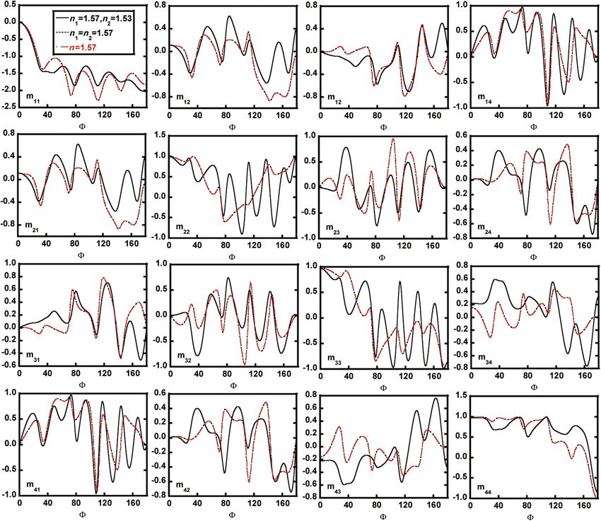
program for scattering medium containing orderly arranged Figure 4 shows the retardance (δ) from the simulated data as
birefringent cylinders. functions of the radial and axial refractive indices difference Δnc
It can be seen from Fig. 3, for both the well-aligned nonbir- and diameters of the cylinders. The diameters of the cylinders
efringent or birefringent cylinders, m12 and m21 are nearly equal, are from 0.6 to 2 μm, and the values of birefringence Δnc are
and m22 is significantly bigger than the other polarization depen- from 0 to 9 × 10⁻³ ; the thickness of the medium is 1 cm.
dent elements. For the Mueller matrix elements m33 and m44 , Figures 4(a)–4(c), respectively, represent three cases of different
however, they are different for the birefringent and nonbirefrin- scattering coefficients, μs ¼ 10, μs ¼ 20, μs ¼ 30 cm−1 . It can
gent cylinders, probably due to the intrinsic birefringence on be seen that the contributions by the birefringent cylinders to the
cylindrical scatters. Considering the possible small fluctuation retardance strongly depend on their diameter and density. For
of arrangement and size for cylinders during the preparation Δnc ¼ 0, the retardance decreases as the diameter of the cylin-
of experimental phantoms, the slight differences between ders increases and increases as the scattering coefficient
experiments and simulations are possibly due to the uncertainty increases, as found in the previous work.13 There is a good pos-
of the simulation approximation. Further simulations with dif- itive linear relationship between δ and the intrinsic birefringence
ferent parameters in the model show that the effects on the of the cylinders, which appear to be very similar to the effects
Mueller matrix elements due to the birefringence in the cylin- due to the birefringent medium between scatterers.13 The slope
drical scatterers are complicated and sensitive to the diameter of the retardance-birefringence curves is shown in Fig. 4, which
and refractive indices of the cylinders. represents how sensitively the retardance varies with the
Fig. 3 Experimental and simulation results of forward scattering Mueller matrix. (a) and (b) are exper-
imental and simulated results of birefringent cylinders (well-aligned silk fiber). (c) and (d) are experimental
and simulated results of nonbirefringent cylinders (well-aligned glass fiber).
Journal of Biomedical Optics 065001-4 June 2014 • Vol. 19(6)
Downloaded From: https://www.spiedigitallibrary.org/journals/Journal-of-Biomedical-Optics on 12 Feb 2022
Terms of Use: https://www.spiedigitallibrary.org/terms-of-useGuo et al.: Study on retardance due to well-ordered birefringent cylinders. . .
Fig. 4 The relationship between the birefringence of the cylinders and the retardance δ. Different curves
represent different diameters of birefringent cylinders, (a)–(c) represent different scattering coefficients of
the sample.
Fig. 5 Slopes extracted from Figs 4(a)–4(c), (a) and (c) represent the relationship between the diameter
and scattering coefficient μs and δ, (b) and (d) represent the relationship between the product of diameter
d and scattering coefficient μs and δ.
Journal of Biomedical Optics 065001-5 June 2014 • Vol. 19(6)
Downloaded From: https://www.spiedigitallibrary.org/journals/Journal-of-Biomedical-Optics on 12 Feb 2022
Terms of Use: https://www.spiedigitallibrary.org/terms-of-useGuo et al.: Study on retardance due to well-ordered birefringent cylinders. . .
only on the order of magnitude of 102 , indicating that the intrin-
sic birefringence of cylindrical scatterers has weaker influence
on the total retardance than the birefringence of the ambient
medium.
5 Conclusion
We established an anisotropic scattering model including bire-
fringent cylinders with different refractive indices along the
radial and axial directions and developed the corresponding
Monte Carlo simulation program. The validity of simulation
program is tested by experiments using well-aligned nonbire-
fringent and birefringent cylinders. The present study shows
Fig. 6 Change in the birefringence of the medium surrounding the that the retardance due to scattering of well-ordered birefringent
nonbirefringent cylinder. The diameters of the cylinder were 1.0, cylinders comes from two sources: scattering by nonbirefringent
1.4, and 2.0 μm, and the scatter coefficient is μs ¼ 20 cm−1 ; the bire- cylinders and an additional part associated with the intrinsic
fringence of the ambient medium Δn m varies from 0 to 5 × 10⁻⁶ . birefringence on cylinders. Moreover, the retardance increases
linearly with Δnc and almost linearly with the diameter of
birefringence on the cylinder, and also increases with the diam- the birefringent cylinder. We also compare the influence of
the birefringent cylinders on the retardance with our previous
eter of the birefringent cylinders and the scattering coefficient.
cylinder-birefringence model. For the same birefringence, the
We extract the values of slopes of the curves by linear function
birefringent cylinders usually contribute much less to the retard-
fitting. We plot in Figs. 5(a) and 5(c) these slopes as functions of
ance δ than the birefringent medium.
the diameter and scattering coefficient of the birefringent
cylinders. After a normalized transformation of abscissa axis
by d · μs, Figs. 5(a) and 5(c) change into Figs. 5(b) and 5(d); Acknowledgments
there is a clear positive and approximately linear correlation We acknowledge financial support from the National Natural
between the slope and the product of cylinder diameter and Science Foundation of China (NSFC) Grant Nos. 11174178,
density. 61205199, and 11374179.
In addition, we did some investigation about depolarization
(Δ) and diattenuation (D) in the birefringent cylinders model.
We can find that, compared with the retardance, Δ and D References
just have a small fluctuation with the birefringence on the bire- 1. K. S. Saladin, Anatomy and Physiology, Watnick, New York (2010).
fringent cylinders. 2. A. F. Huxley and R. Niedergerke, “Measurement of the striations of
In the previous study,13 we have analyzed the contributions isolated muscle fibers with the interference microscope,” J. Physiol.
of retardance by the nonbirefringent cylinders with the birefrin- 144(3), 403–425 (1958).
gent medium between scatterers. According to our previous 3. J. J. Pasquesi et al., “In vivo detection of exercised-induced ultrastruc-
tural changes in genetically-altered murine skeletal muscle using polari-
research work, Fig. 6 shows δ as functions of the medium bire- zation-sensitive optical coherence tomography,” Opt. Express 14(4),
fringence in the cylinder-birefringence sample. The retardance δ 1547–1556 (2006).
increases linearly with the birefringence of the ambient medium 4. S. N. Savenkov et al., “Light transmission in inhomogeneous birefrin-
Δnm and decreases with the diameter of the cylinders. Here, we gent medium as a function of propagation and observation angles,”
compare two types of birefringence, respectively, in the birefrin- J. Quant. Spectrosc. Radiat. Transfer 110(14), 1441–1447 (2009).
5. H. He et al., “Application of sphere-cylinder scattering model to skeletal
gent cylinders and the cylinder-birefringence sample. For the
muscle,” Opt. Express 18(14), 15104–15112 (2010).
birefringent-cylinder scattering samples (Figs. 4 and 5), the 6. M. F. G. Wood, X. Guo, and I. A. Vitkin, “Polarized light propagation in
diameter of the cylinders plays an important role on the retard- multiply scattering media exhibiting both linear birefringence and opti-
ance. However, for the cylinder-birefringence model, the bire- cal activity: Monte Carlo model and experimental methodology,”
fringent medium surrounding the nonbirefringent cylinder is J. Biomed. Opt. 12(1), 014029 (2007).
the major source of the total retardance. 7. A. Pierangelo et al., “Polarimetric imaging of uterine cervix: a case
study,” Opt. Express 21(12), 14120–14130 (2013).
In Fig. 6, the well-aligned nonbirefringent cylinders are in 8. N. Ghosh, M. F. G. Wood, and I. A. Vitkin, “Mueller matrix decom-
parallel to the birefringence axis of the birefringent medium, position for extraction of individual polarization parameters from com-
where the Δnm range is set to a smaller scale to ensure δ plex turbid media exhibiting multiple scattering, optical activity, and
stays in the range of 0 to π. The scattering coefficient of cylin- linear birefringence,” J. Biomed. Opt. 13(4), 044036 (2008).
ders affects only the initial value of the retardance, but not the 9. X. Wang and L. V. Wang, “Propagation of polarized light in birefringent
slope of the curve. turbid media: a Monte Carlo study,” J. Biomed. Opt. 7(3), 279–290
(2002).
For the birefringent medium, the retardance can be written as 10. H. He et al., “Two-dimensional backscattering Mueller matrix of
δ ¼ 2πnm sΔnm ∕λ, where s is the projection along the x direc- sphere-cylinder scattering medium,” Opt. Lett. 35(14), 2323–2325
tion of the moving distance between two successive scattering (2010).
events, Δnm is the birefringence of the medium, nm is the aver- 11. T. Yun et al., “Monte Carlo simulation of polarized photon scattering in
age refractive index, and λ is the wavelength of light. If we set anisotropic media,” Opt. Express 17(19), 16590–16602 (2009).
12. E. Du et al., “Two-dimensional backscattering Mueller matrix of sphere-
the same birefringence parameter as Fig. 6, the coefficient
cylinder birefringence media,” J. Biomed. Opt. 17(12), 126016 (2012).
2πnm s∕λ is nearly equal to the slope of curves in Fig. 6, 13. Y. Guo et al., “A study on forward scattering Mueller matrix decompo-
which is around 104 –105 . By contrast, in the birefringent cyl- sition in anisotropic medium,” Opt. Express 21(15), 18361–18370
inders samples, the slope of the curves shown in Fig. 5 is (2013).
Journal of Biomedical Optics 065001-6 June 2014 • Vol. 19(6)
Downloaded From: https://www.spiedigitallibrary.org/journals/Journal-of-Biomedical-Optics on 12 Feb 2022
Terms of Use: https://www.spiedigitallibrary.org/terms-of-useGuo et al.: Study on retardance due to well-ordered birefringent cylinders. . .
14. M. Shribak and R. Oldenbourg, “Techniques for fast and sensitive mea- 18. X. B. Wu and K. Yasumoto, “Three-dimensional scattering by an infin-
surements of two-dimensional birefringence distributions,” Appl. Opt. ite homogeneous anisotropic circular cylinder: an analytical solution,”
42(16), 3009–3017 (2003). J. Appl. Phys. 82, 1996–2003 (1997).
15. B. Peng, T. Ding, and P. Wang, “Propagation of polarized light through 19. C. F. Bohren and D. R. Huffman, Absorption and Scattering of Light by
textile material,” Appl. Opt. 51(26), 6325–6334 (2012). Small Particles, John Wiley & Sons, New York (1983).
16. V. V. Tuchin, L. V. Wang, and D. A. Zimnyakov,” Tissue structure and 20. W. D. Yu and C. Y. Chu, Eds., Textile Physics, 2nd ed., Donghua Press,
optical models,” Chapter 2 in Optical Polarization in Biomedical Shanghai (2009).
Applications, Elias Greenbaum, Ed., pp. 7–28, Springer, New York 21. S. Y. Lu and R. A. Chipman, “Interpretation of Mueller matrix based
(2006). on polar decomposition,” J. Opt. Soc. Am. A 13(5), 1106–1113
17. J. C. Monzon, “Three-dimensional scattering an infinite homogeneous (1996).
anisotropic circular a spectral approach,” IEEE Trans. Antennas
Propag. 35, 670–682 (1987). Biographies of the authors are not available.
Journal of Biomedical Optics 065001-7 June 2014 • Vol. 19(6)
Downloaded From: https://www.spiedigitallibrary.org/journals/Journal-of-Biomedical-Optics on 12 Feb 2022
Terms of Use: https://www.spiedigitallibrary.org/terms-of-useYou can also read