Towards Robust Robot Control in Cartesian Space Using an Infrastructureless Head- and Eye-Gaze Interface - MDPI
←
→
Page content transcription
If your browser does not render page correctly, please read the page content below
sensors
Article
Towards Robust Robot Control in Cartesian Space Using an
Infrastructureless Head- and Eye-Gaze Interface
Lukas Wöhle *              and Marion Gebhard

                                          Group of Sensors and Actuators, Department of Electrical Engineering and Applied Sciences,
                                          Westphalian University of Applied Sciences, 45877 Gelsenkirchen, Germany; marion.gebhard@w-hs.de
                                          * Correspondence: lukas.woehle@w-hs.de

                                          Abstract: This paper presents a lightweight, infrastructureless head-worn interface for robust and
                                          real-time robot control in Cartesian space using head- and eye-gaze. The interface comes at a total
                                          weight of just 162 g. It combines a state-of-the-art visual simultaneous localization and mapping
                                          algorithm (ORB-SLAM 2) for RGB-D cameras with a Magnetic Angular rate Gravity (MARG)-sensor
                                          filter. The data fusion process is designed to dynamically switch between magnetic, inertial and visual
                                          heading sources to enable robust orientation estimation under various disturbances, e.g., magnetic
                                          disturbances or degraded visual sensor data. The interface furthermore delivers accurate eye- and
                                          head-gaze vectors to enable precise robot end effector (EFF) positioning and employs a head motion
                                          mapping technique to effectively control the robots end effector orientation. An experimental proof
                                          of concept demonstrates that the proposed interface and its data fusion process generate reliable
                                          and robust pose estimation. The three-dimensional head- and eye-gaze position estimation pipeline
                                          delivers a mean Euclidean error of 19.0 ± 15.7 mm for head-gaze and 27.4 ± 21.8 mm for eye-gaze at
                                a distance of 0.3–1.1 m to the user. This indicates that the proposed interface offers a precise control

                                          mechanism for hands-free and full six degree of freedom (DoF) robot teleoperation in Cartesian space
Citation: Wöhle, L.; Gebhard, M.
                                          by head- or eye-gaze and head motion.
Towards Robust Robot Control in
Cartesian Space Using an
                                          Keywords: data fusion; MARG-sensors; hands-free interface; pose estimation; human robot collabo-
Infrastructureless Head- and
                                          ration; robot control in cartesian space; multisensory interface; gaze control
Eye-Gaze Interface. Sensors 2021, 21,
1798. https://doi.org/10.3390/
s21051798

Academic Editor: Santiago T. Puente       1. Introduction
                                               Direct human robot collaboration demands robust interfaces to interact with or control
Received: 8 February 2021                 a robotic system in a human safe manner. Especially in situations where the hands of a
Accepted: 3 March 2021                    person are either occupied (industry 4.0) or not usable, e.g., people with severe physical
Published: 5 March 2021                   disabilities, a safe, reliable and intuitive communication source that enables a direct interac-
                                          tion with the robotic system should be provided. In the context of assistive robotics, most
Publisher’s Note: MDPI stays neutral      of these interfaces have been designed hands-free [1–3].
with regard to jurisdictional claims in        A robust hands-free interface provides the opportunity for people suffering from phys-
published maps and institutional affil-   ical motor impairments the opportunity to be (re)integrated into working life, e.g., for pick
iations.
                                          and place tasks in a library workplace designed for people with tetraplegia [4]. The question
                                          of how an interface could be designed to effectively and intuitively allow for hands-free
                                          robot control has drawn significant research attention in the last decade [5,6]. Recent
                                          approaches focus on the use of head motion or eye-gaze tracking data to allow for direct
Copyright: © 2021 by the authors.         robot control since both modalities are naturally correlated with direct interaction intention
Licensee MDPI, Basel, Switzerland.        and enable accurate control mechanisms [7]. Gaze based control signals can accelerate and
This article is an open access article    simplify human robot collaboration, especially when it comes to object targeting in pick and
distributed under the terms and           place tasks which is essential in the context of human robot collaboration [2,8]. We divide
conditions of the Creative Commons
                                          gaze into two subcategories based on the modality used to extract the gaze vector. The most
Attribution (CC BY) license (https://
                                          known gaze vector is eye-gaze. Eye-gaze vectors represent the three-dimensional vector
creativecommons.org/licenses/by/
                                          from the humans eye to a target gaze point. The direction of the vector changes based on
4.0/).

Sensors 2021, 21, 1798. https://doi.org/10.3390/s21051798                                                 https://www.mdpi.com/journal/sensors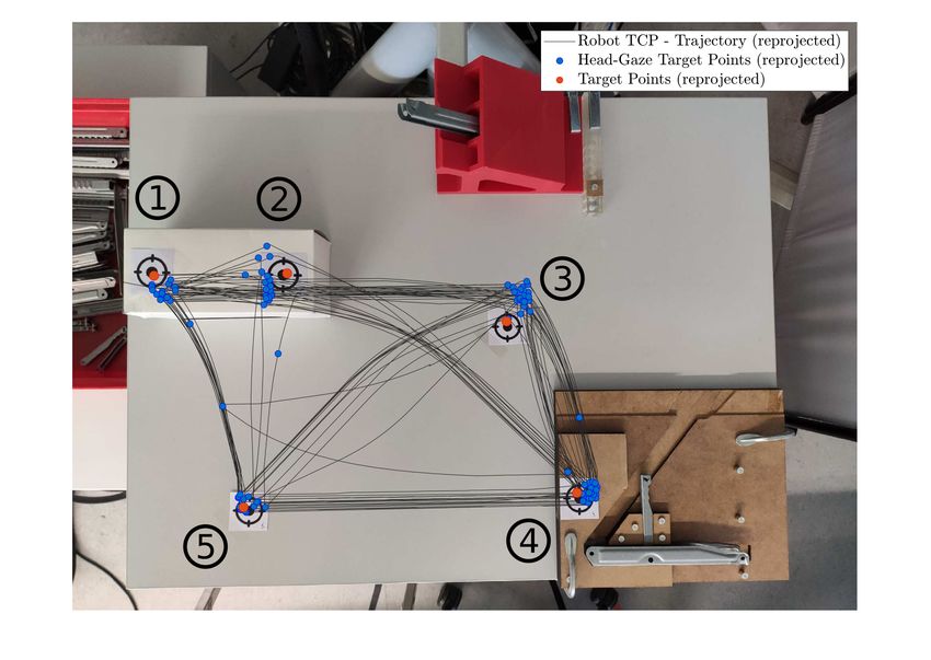
Sensors 2021, 21, 1798 2 of 28
the eye motion [9]. Head-gaze on the other hand describes a vector that is orthogonal with
respect to the rotation axis of the humans head and perpendicular to the face. The direction
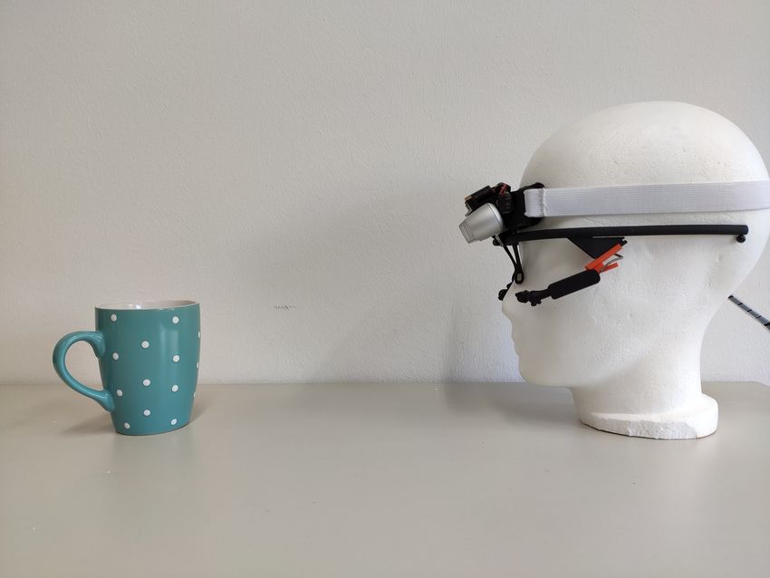
of the vector depends on the orientation of the head [10], see Figure 1b for a depiction of
gaze vectors. Accuracy, affordability and mobility are key factors for eye or head-gaze
based interfaces to enable intuitive human robot collaboration and to transfer research and
development to further applications and end users.
This paper presents a lightweight, infrastructureless head-worn interface for robust
and real-time robot control with a total weight of just 162 g, see Figure 1a. It allows for head
motion, head-gaze and eye-gaze based robot teleoperation in six degrees of freedom (DoF),
three DoF translation and rotation, respectively. The interface combines a head-worn eye
tracker, an RGB-D world camera and a custom MARG-sensor board to calculate the users
head pose and a 3D gaze point which is the input target point for the robotic end effector
in Cartesian position coordinates. The interface furthermore enables orientation control of
the end effector (EFF) by using direct head motion mapping based control.
2. State of the Art Head and Eye-Gaze Interfaces
Recent Interfaces focus on the use of head motion or eye tracking data to allow for
continuous robot control and deliver a low-cost and intuitive control mechanism [6,11].
Head motion based interfaces usually employ low-cost sensors, i.e., Magnetic Angu-
larRate Gravity (MARG)-sensors, to estimate orientation without a need for static infras-
tructure, e.g., markers, that would limit the useable motion range and environment [1].
The orientation estimation from these sensors is based on the angular rate integration
measured by the gyroscope. This raw signal suffers from various noise terms, especially
gyroscope offset, that result in drift of the orientation estimation and therefore reduces
accuracy. The drift is usually compensated by using global reference vector measurements
from accelerometer and magnetometer [12,13]. Whether a magnetometer can be used to
correct for heading errors depends on the magnetic environment [14]. Since the magnetic
environment for robotic collaboration is at most unstable in indoor environments and
nearby the robot, functional safety cannot be guaranteed when using MARG-sensors only.
Some industrial-grade commercially available MARG-sensor systems offer strategies to en-
able a robust orientation estimation in magnetically challenging environments, e.g., XSens
MTi series. This MARG-sensor has a build in feature called active heading stabilization
(AHS) to enable a low drift unreferenced yaw orientation estimation. This feature is able
to deliver yaw drift as low as 1–5 degrees per hour depending on the application [15].
Besides orientation, MARG-sensors can be used to estimate position, at least for a certain
period of time. Centimeter accurate position estimation with MARG-sensors however is
typically based on data fusion with external sensors (e.g., GPS) [15]. In GPS denied envi-
ronments (indoor applications) dead reckoning based on MARG-sensors only can be used.
This method relies on double integration of the acceleration to extract velocity and position.
The double integration step will accumulate every minuscule error and position accuracy
decreases rapidly. Depending on the desired application, MARG-sensor only orientation
and position estimation accuracy’s might be sufficient. In a human robot collaboration
scenario these errors should ideally be removed completely or be kept at a minimum. This
is especially true when it comes to 3D gaze point estimation in Cartesian space. A precise
position estimation must be proved to calculate an accurate gaze position in Cartesian
space. Every head position error will directly influence the gaze point prediction. Therefore,
other heading reference sources should be provided to account for the orientation and
position drift. Furthermore, using head motion only comes at the cost of having to switch
between various motion groups to map from underrepresented 3D motion space of the
head to the full 6D end effector motion range.
Eye-gaze based robot control utilizes the natural eye motion of a human. A recent
approach utilizes 2D gaze points and gaze gestures to control the pose of a robotic arm
in three-dimensional space [11]. The user can switch between motion groups by gaze
gestures to control the arm in various directions (xy-plane, z-plane, rotational xy, rotational
Sensors 2021, 21, 1798                                                                                            3 of 28

                         z) and control the robot by gazing at a dynamic command area (ROI) at the center of the
                         robots’ gripper. This interface needs to track the robots EFF position in order to specify
                         the dynamic command areas and therefore needs a fiducial marker at the EFF, so it relies
                         on infrastructure in terms of stationary markers in the real world scenario. Furthermore,
                         the interface needs more motion group transitions since it only generates two-dimensional
                         commands for a six dimensional control problem.
                               Tostado et al. [16] proposed an interface decoding eye-gaze into a position in 3D space
                         for robotic end point control. The proposed system is capable of controlling a robotic end
                         effector in 3D space by directly gazing at a specific object or point. The system consists of
                         two stationary eye cameras in front of the user and thus is dependent on the infrastructure
                         which limits the possible workspace related to camera field of view and motion range.
                         Furthermore, the system does not include head tracking capabilities and therefore assumes
                         a fixed head position, which is ensured by a chin rest, further reducing mobility.
                               Scalera et al. [17] present a robotic system that enables robotic painting by eye-gaze.
                         The work addresses the prior mentioned mobility restrictions by using a remote eye
                         tracking bar (Tobii Eye Tracker 4C) which enables accurate eye-gaze tracking on a computer
                         screen and accounts for head motions of the user. The filtered eye-gaze coordinates on
                         the computer screen are the input coordinates for the TCP position on the canvas. This
                         approach eliminates most mobility restrictions but relies on the stationary eye-tracking
                         camera attached to a computer screen and only supports two-dimensional commands in a
                         single plane from the computer screen mapped onto the robots’ workspace.
                               Dezmien et al. [18] developed an interface for eye-gaze based robotic writing and
                         drawing. Similarly to Scalera et al. this work utilizes a remote eye tracking bar (Tobii Eye X)
                         to track eye gaze points of a user on a 2D canvas to directly control a robotic arm drawing
                         on the canvas. The approach uses the Tobii Eye X’s head tracking capability to attach or
                         detach the pen on the canvas. Likewise to the prior mentioned approach, the interface
                         enables direct low cost eye-gaze robot control but relies on the stationary camera hardware
                         and is applicable only in a two-dimensional plane.
                               A recent approach delivers a potential interface for a full eye-gaze based control of
                         a robotic arm by combining eye tracking, head tracking and depth information [2]. This
                         interface however is dependent on a stationary infrared motion tracking system for head
                         pose estimation. The motion capture system cannot be used in mobile applications and
                         furthermore exceeds reasonable costs for a control interface. The control approach only
                         includes three-dimensional end effector position control and does not include end effector
                         orientation. The control approach utilizes the human operators hand as the end effector
                         rather than a robotic gripper. The operators hand is coupled to the robotic arm by a
                         magnetic coupling and therefore can only be used by people that are able to close their
                         hands and grab an object.
                               The HoloLens 1 is a commercially available interface that is capable of delivering
                         accurate three-dimensional head-gaze but lacks the ability to track eye positions and deliver
                         eye-gaze. The HoloLens one is weighing 579 g in total [19]. The center of mass is at the
                         front of the head and might therefore be too heavy for long uses from people with severe
                         physical disabilities. The new generation of the HoloLens, the HoloLens 2, is able to
                         deliver eye and head-gaze vectors and comes at a total weight of 566 g distributed more
                         equally [20]. To the best of our knowledge, it has yet to be researched if the HoloLens 2 is
                         more suitable for people with severe physical disabilities in long term use.
                               With the recent technological advantages in camera miniaturization, mobile eye track-
                         ing and computer vision this work aims to fill the gap and propose an infrastructureless
                         and lightweight solution for accurate head- and eye-gaze based six DoF robot control in
                         Cartesian space to facilitate hands free and multi-modal human robot collaboration. It
                         enables head motion, head-gaze and eye-gaze based robot teleoperation in six degrees of
                         freedom. The interface combines a binocular head-worn eye tracker, a low-cost RGB-D
                         world camera and a low-cost custom MARG-sensor board to calculate the users head pose
                         and gaze point in three-dimensional space with respect to a user defined world coordinate
Sensors 2021, 21, 1798                                                                                          4 of 28

                         system. The proposed system does not rely on stationary cameras and is therefore infras-
                         tructureless and mobile regarding potential operational environments and usable motion
                         space. The interface utilizes a state of the art and completely open source visual SLAM
                         (simultaneous localization and mapping) approach, namely ORB-SLAM 2 [21] and fuses
                         it with the orientation measurements of a MARG-sensor board to estimate an accurate
                         head pose. The proposed data fusion enables a robust orientation estimation, even when
                         visual data is lost for a large period of time (≥25 s). For eye-gaze control, a lightweight
                         binocular eye tracker is used to extract a 3D gaze point from the RGB-D cameras depth
                         image which is transformed into the coordinate system defined by the estimated head pose.
                         Head-gaze control is achieved by using the depth cameras center pixel as the gaze vector
                         origin. The three-dimensional gaze point is used as the input control for the robotic end
                         effector. Another feature of the interface is switching from Cartesian position to Cartesian
                         orientation control by a simple eye blink. The end effectors’ orientation control is based on
                         the head motion mapping presented in [1]. An eye safe laser embedded into the interface
                         shows the head-gaze vectors endpoint for direct user feedback.

                         3. Head- and Eye-Gaze Interface
                              Within this work an interface for six dimensional robot teleoperation in Cartesian
                         space, with three dimensions for orientation and three dimensions for position control,
                         respectively, is proposed. This interface is capable of head- or eye-gaze based point-to-
                         point position teleoperation of a robotic arm as well as head motion based EFF orientation
                         control. This is achieved by combining an active infrared stereo camera and a custom
                         MARG-sensor in a 3D printed case that is mounted on top of a mobile binocular eye tracker.
                         The interface is independent of external infrastructure and therefore usable within most
                         indoor environments.

                         3.1. Interface System Setup
                              The Interface consists of three main hardware parts. The infrared stereo camera,
                         a custom MARG-sensor board and a binocular mobile eye tracker with a USB-C world
                         camera connector. This hardware setup tackles various software tasks which rely on each
                         other and enable the robot teleoperation. We divide these tasks into the following categories
                         and explain them in detail in the subsections below: (A) 3D head pose estimation through
                         visual and inertial data fusion, (B) 3D gaze estimation with respect to the robot coordinate
                         frame and (C) the application interface for the robot control. To align all coordinate frames
                         the head pose estimation block also features an input for any absolute pose measurement
                         system (e.g., fiducial marker based pose estimation, infrared marker pose estimations or
                         a three point coordinate system alignment procedure). All software components besides
                         the MARG-filter framework are written in C++ and embedded in the Robot Operating
                         System (ROS) [22]. ROS enables fast and reliable inter device and software networking.
                         The framework already delivers a lot of software packages to interface various robots,
                         vision systems and much other hardware which enables fast integration and merging of
                         the proposed system into various applications. Figure 2 depicts a general overview of the
                         proposed Interface and its associated hard- and software components.

                         3.2. Interface Hardware Setup
                               In this work we use an active infrared stereo camera, namely the d435 from Intel® Re-
                         alSense™ [23]. This camera uses stereo image rectification to estimate depth. Furthermore,
                         it offers an infrared image projector to illuminate the scene for dense depth estimation
                         at varying lighting conditions. The camera provides calibrated and rectified infrared
                         images, depth image and RGB image at up to 90 frames per second depending on the
                         image size. The camera is attached to a custom 3D printed camera mount with tabs for a
                         headband. The camera mount also features an encapsulation for a custom MARG-sensor
                         board. The MARG-sensor system features an Espressif 32 bit dual-core microcontroller
                         unit (MCU) as well as a low power 9-axis ICM 20948 InvenSense MARG-sensor. The MCU
Sensors 2021, 21, 1798 5 of 28
is running the FreeRTOS real-time operating system on both cores at 1 kHz scheduler tick
rate. The MCU publishes and receives data at 100 Hz via micro-USB over full-duplex
UART [24]. One of the GPIO’s is directly soldered to an eye-safe m1 visible red laser, which
is centered above the first d435 cameras infrared image sensor. This laser is dot is used
for direct user feedback but is not involved in the position or orientation estimation. This
custom sensor mount is resting on a binocular eye tracker frame. We use the open source
pupil core binocular c-mount eye tracker for this purpose [25]. The d435 is connected
to the USB-C plug of the eye tracker. The camera mount has a notch that is placed over
the glasses frame and can be secured via a headband on the users head. This stabilizes
the camera with respect to the eye tracker and distributes forces from the nose rest of the
tracker to the complete circumference of the head therefore reducing slippage from the eye
tracker and increases wearing comfort. The complete Interface weighs 162 g. Figure 1a
depicts the designed Interface. The interface USB cables are plugged into a standard laptop
computer that is running the various C++ nodes on the ROS software stack, compare
Figure 2. The laptop is equipped with a 64 Bit i5-5941 quad-core CPU and 6 GB of RAM
running Ubuntu 16.04 with ROS version kinetic.
y
x
z B
head-gaze
eye-gaze
P
z
y
x
N
(a) (b)
Figure 1. Proposed head interface (a) and depiction of head- and eye-gaze vectors (b). The head
interface (a) consists of a pupil core binocular USB-C mount headset ¯ and the custom camera mount
uniting the depth camera ®, MARG-sensor ¬ and feedback laser . Image (b) depicts head- and
eye-gaze vector origins from the interface to a world point P.
A) 3D Head Pose
ω ~ f~
~ , m, N
Bq
MARG- MARG-Filter
sensor Framework
~v
N
Infrared, ~t N
RGB-D-
Depth
RGB-D SLAM B q0
Head Pose Initial Pose
camera Framework estimate (w.r.t. Robot)
N~
B) 3D Gaze [N
B q, t] C) Application
Eye- Gaze Mapper 3D Gaze Robot Control
camera u, v
d~ Transformer N
d~
Figure 2. Block diagram of the overall system setup. The system consists of three main Soft- and
Hardware components that enable the calculation of robust control signals for robotic teleoperation:
(A) The accurate head pose estimation based on visual-inertial position and orientation estimation,
(B) the calculation of 3D eye- and head-gaze from known head pose and gaze points from dense 3D
depth images as well as (C) the application interface for robot control in 6D Cartesian space.
Sensors 2021, 21, 1798                                                                                           6 of 28

                         3.3. 3D Head Pose Estimation
                               The head pose estimation block A) from Figure 2 combines visual odometry and a
                         revised version of our previous MARG-filter framework. The visual odometry estimation
                         is based on a visual SLAM algorithm (ORB SLAM 2) [21]. The MARG-sensor orientation
                         estimation filter framework is explained in detail in [12,24].
                               The proposed data fusion addresses the environmental challenges which arise from
                         the teleoperation task and is not reliably solvable using only a single sensing technology.
                         For example, the orientation estimation from MARG-sensors is based on the numerical
                         integration of angular rate measured through the gyroscope. These low-cost consumer
                         grade MEMS based gyroscopes suffer from DC-offsets, known as gyroscope bias. This bias
                         leads to a drift in the integrated angles. This drift is typically compensated by using global
                         references, i.e., direction of gravity and geomagnetic field of the earth measured by the
                         accelerometer and magnetometer, in the data fusion process. However, the measurements
                         are subject to external disturbances effecting the measured direction of the reference vectors
                         and therefore leading to orientation estimation errors. This is especially the case for the
                         measurement of the geomagnetic field vector used to correct heading estimation errors.
                         Indoor scenarios and the presence of ferromagnetic and permanent magnetic materials
                         (e.g., robotic systems) will lead to varying magnetic field vectors which degrade the effect
                         from the geomagnetic vector measurement on the heading correction. Within this work we
                         use visual odometry data in the data fusion process of the MARG-sensor to apply heading
                         correction and improve absolute orientation estimation in indoor scenarios. On the other
                         hand, the sole use of visual odometry is not robust related to the proposed scenario. Using
                         vision based techniques only (e.g., optical flow) would also result in accumulations of
                         errors since the visual scenery will be exposed to a lot of relative motion from the robotic
                         system. Robust visual odometry is based on the dominance of static feature points over
                         moving objects and therefore degrades in the presence of moving objects, in this case the
                         moving robot system.
                               To address these issues this work utilizes a visual SLAM approach to (a) create an
                         accurate map of the working area to relocalize within the map based on the detected and
                         matched features in order to increase accuracy and robustness and (b) fuse the measure-
                         ments with MARG-sensor data to reduce the impact of relative motion in front of the
                         cameras visual scene on the orientation estimation and (c) to be able to reset to a known ori-
                         entation based on the discrete MARG-sensor estimations. The head pose estimation block
                         fuses visual and inertial sensor readings to form a robust pose estimation of a users head
                         without the need for external marker placement, i.e., fiducial markers. Due to the recent
                         technology and research efforts in camera technologies, depth camera sensors have become
                         small, fast, reliable and affordable when it comes to everyday use. Using a depth camera
                         over a regular monocular 2D image sensor adds a complete new dimension and has major
                         advantages when it comes to pose estimation in general. We therefore use a stereo depth
                         camera as the input measurement for a visual SLAM approach and combine the orientation
                         measurement with a MARG-sensors orientation estimation to generate reliable and robust
                         orientation even under complete loss of visual information. The visual position estimation
                         is used as true head position since MARG-sensors are known for accumulating errors upon
                         estimating translation from double integration of acceleration and might therefore lead to
                         wrong position estimation.

                         3.3.1. Visual SLAM Based Pose Estimation
                              The visual SLAM framework is part of block A, the head pose estimation pipeline in
                         Figure 2. In this work we use a state of the art and open source V-SLAM approach, namely
                         ORB-SLAM 2 [21]. This algorithm has proven to be very robust and precise regarding
                         position and orientation estimation, which is in general referred to as pose. The V-SLAM
                         approach uses ORB (Oriented FAST and Rotated BRIEF) to detect and track features from
                         an RGB-D input image.
Sensors 2021, 21, 1798                                                                                          7 of 28

                              We use the RGB-D based implementation of ORB-SLAM 2 but instead of supplying
                         the RGB image, we use the infrared image of the first infrared camera sensor from the
                         stereo infrared module of the RealSense™ d435 camera (Intel Corporation, Santa Clara,
                         CA, USA). This image is the basis for the depth image alignment. This avoids the need for
                         an alignment step between RGB and depth image. Furthermore, the RGB camera is rolling
                         shutter whereas the infrared cameras have global shutter and will therefore contain less
                         motion blur. The infrared cameras also features a wider field of view (FOV) compared to
                         the RGB camera (H × V × D-Infrared: 91.2◦ × 65.5◦ × 100.5◦ , vs. RGB: 64◦ × 41◦ × 72◦
                         [23]). Using the infrared image decreases the data package throughput send out by the
                         camera. The d435 camera provides the possibility to toggle the laser emitter projector
                         between two consecutive frames. Thus, one image frame is taken with and the next frame
                         without the emitter projector. Images without emitter projector are used as the 2D-image
                         input source to the ORB-SLAM framework, whereas the depth images are provided by the
                         depth estimations from the images with emitter projection. This is enabled by calculating
                         the mean image brightness and selecting the image with lesser brightness as the 2D-image
                         source and the one with higher brightness as the depth source for an increased depth image
                         density, respectively. Additionally, this dense depth image is used as the input to the gaze
                         mapper, compare Figure 2.
                              Figure 3 shows the image pipeline outputs with and without emitter projector for
                         infrared and depth streams. Using the above described image pipeline decreases the
                         necessary data package size that needs to be handled by the host computer. Furthermore,
                         this procedure ensures a wider FOV image for the visual SLAM algorithm and gaze
                         mapping instead of using the RGB image. The visual SLAM framework will locate and track
                         ORB features in the current infrared and associated depth image and inserts keyframes into
                         a new map. Based on epipolar geometry and fundamental matrix construction the camera
                         pose (orientation and position) is estimated using a constant velocity model between
                         consecutive frames and optimized through bundle adjustment. ORB SLAM is capable of
                         loop closure during map creation and furthermore relocalizes the camera when re-visiting
                         known locations inside the generated map [21]. The ORB-SLAM framework features a
                         localization only mode to reduce computational costs that can be enabled if a sufficient
                         map has been captured.

                         Figure 3. Image sequence as seen by the filtered camera outputs. Left, image without emitter
                         projector, middle, image with emitter projector pattern (white spots) and right, depth image.

                              This algorithm is capable of generating reliable position and orientation data while
                         visual frames are available. If a sufficient large map has been created (>50 keyframes)
                         we enable the localization only mode to reduce computational costs and reduce pose
                         estimation errors from relative motion in the visual scenery. To further enhance robustness,
                         we disable the visual odometry constant velocity motion model within the localization
                         mode. This ensures that the pose estimation does rely on matched feature points in the
                         map only and does not interpolate between unmatched features using the velocity model.
                         On the one hand this procedure ensures that the visual pose estimation is less error-prone
                         to relative motion in the scene. On the other hand the overall tracking robustness of
                         ORB-SLAM is reduced which will result in localization failures during strong dynamic
                         motion. If ORB-SLAM fails to localize in the scene the mapping mode is enabled again.
                         The visual SLAM framework passes the visual orientation data to the MARG-filter for data
                         fusion purposes described in Section 3.3.2. The visual SLAM framework directly provides
                         the head position data to the complete head pose estimate, see Figure 2. There is no need
Sensors 2021, 21, 1798 8 of 28
to fuse the position data from the visual SLAM framework, as the position estimation from
the MARG-sensor is not reliable due to drift. The manufacturing immanent DC-offset of
the MEMS accelerometer leads to a second order drift phenomenon based on the double
integration of accelerometer raw sensor data. The orientation estimation from the visual
SLAM approach however is passed to the MARG-filter framework. A reliable orientation
calculation is provided by the MARG-filter framework even when visual feedback is lost
or compromised by relative motion, e.g., the robotic system moving through the scenery.
The MARG-filter framework bridges the downtime of the visual data and furthermore
reinitializes the visual SLAM algorithm by passing the current orientation as the initial state.
3.3.2. Visual-Inertial Orientation Fusion
The second algorithm to robust pose estimation utilizes MARG-sensor measurements
fused with visual heading information from the V-SLAM approach. The fusion of data are
used to calculate an orientation estimation. Figure 4 gives an overview of the proposed
data fusion approach. Synchronization between the MARG and V-SLAM orientation data
is achieved based on a ROS node using an approximate time policy matching the different
sensors timestamps. The node uses the ROS message_filter package to synchronize the
data packets by finding the minimal timestamp difference from a queue of 20 samples
(MARG and Camera samples). The best matched samples are used to transform and
align the V-SLAM orientation into the MARG-sensor coordinate system. This V-SLAM
based aligned orientation is used to calculate the visual heading information N~ v,k which
is passed to the MARG-filter framework, enabling the calculation of a full quaternion BN q
representing the users head orientation estimation. Even if visual information is lost for a
longer period of time (up to 25 s) or the visual information is degraded because of high
dynamic relative motion in the scene, e.g., the moving robotic system, data fusion allows
for a robust orientation estimation.
MARG Filter Framework
GDA KF
MARG-Sensor
N
B q∇,k Update
∇f
Gyro. N
=N ~a,N~
x̂k = x̂−
k + Kk yk
B qk+1 B qk − µk ||∇f ~||
~
a,N
...
Mag. ~k
N m > yk = z∇,k − H x̂−
k
~ k )=
Heading vector (N Predict
Acc. ~v ∨ N
~m ∨ N~ IM U x̂−
N k+1 = Φkxk − wk
N
B qk+1
...
RGB-D camera ~ v,k
N
Infra-
Image Head Pose
ORB Nq
B v →N
B qv,ψ
(Emitter off)
SLAM 2 Nq →N qφ,θ
B B N
Nq
z −1 B qk+1
N q ,C ~t N =N N
B qv,ψ •B qφ,θ
Depth- C v B qC B vh
Image ~ v =N q • 0 •N q̇
NN N~
N
BT
B vh ~
x B vh tk+1
(Emitter on)
Visual heading
RGB-D SLAM Framework
Figure 4. Block diagram of the data fusion software for head pose estimation. The ORB SLAM 2
node calculates a complete pose in the camera frame which is transformed into the MARG-sensors
navigation frame. The translation vector C~t is transformed into the world coordinate system, forming
N~t and is directly used as the true head position. The head orientation estimation N q is based
B
on the MARG-filter framework incorporating three different correction heading vectors (visual
heading, IMU heading, magnetic heading). The filter chooses the appropriate heading source based
on disturbance recognition from vector scalar product deviations for robust orientation estimation.
The following section first explains the MARG filter framework and secondly intro-
duces the data fusion between visual heading information and MARG-sensor orientation
estimation in more detail. The data fusion process consists out of a dual stage filter that
incorporates a gradient descent filter stage (GDA), calculating a correction quaternionSensors 2021, 21, 1798 9 of 28
based on reference sensors (accelerometer and magnetometer) and fuses it with a gyro-
scope based prediction quaternion inside a linear Kalman filter (KF). The complete filter
derivation is given in [12]. The first filter stage is based on Madgwicks popular method for
calculating orientation by solving a minimization problem that rotates a unit vector into a
measurement vector
~ B~s) = N q · 0 · N q̇ − B0 ,
f ( BN q, N d, (1)
B Nd~ B ~s
where BN q is a quaternion, N d~ unit vector and B~s the measurement vector.
The solution proposed by Madgwick et al. [26] is based on gradient descent algorithm
and can be expressed in general form as
~ B~s)
∇ f ( BN qk , N d,
N
B qk +1 = BN qk − µt , k = 0, 1, 2, . . . , n, (2)
||∇ f ( N q , N d,~ B~s)||
B k
where µt represents the gradient step size.
The MARG-filter framework transfers the iteratively updated quaternion, calculated
at the onboard MCU of the MARG-sensor, to the visual SLAM algorithm. The quaternion
is split into a roll and pitch quaternion as well as a yaw quaternion. The roll and pitch
quaternion is directly used as robust input for orientation information, whereas the yaw
quaternion is corrected within the visual SLAM framework using the V-SLAM based
heading vector. This is because the yaw quaternion is subject to drift originating from the
gyroscope offset, which dynamically changes over time due to temperature and mechanical
packaging conditions. Within this work the gyroscope offset drift in heading direction is
corrected by applying a set of equations to calculate the visual heading vector within the
RGB-D odometry framework. In our previous work we proposed the prior mentioned set
of equations to calculate an IMU heading vector and apply it to a GDA based filter while
magnetic disturbance is present [24]. The IMU heading vector substitutes the magnetometer
vector and therefore reduces the needed sets of equations and guarantees convergence as
well as a continuous quaternion solution to the minimization problem. Furthermore, we
use an updated form of Madgwick’s GDA equations from [27] that decouples the heading
vector update from the pitch and roll update calculation and therefore enhances robustness
when the heading vector is disturbed. The process to calculate the visual heading vector
substitute is as follows.
The quaternion CN qV,k from the V-SLAM algorithm is transformed into the MARG-
sensor body orientation through two-sided quaternion multiplication
N N C N C
q
B V,k = q
B 0 · q · q ·
B rig C V,k B rig ,
q̇ (3)
where CB qrig is the rigid transformation from the origin of the first IR cameras coordinate
frame to the MARG-sensor body frame located at the center of the MARG-sensor housing,
q̇ represents the conjugate quaternion, respectively, and BN q0 is the initial quaternion
that aligns the visual orientation estimation in the navigation frame with the MARG-
sensor orientation.
The heading part of the transformed visual quaternion is extracted using the follow-
ing process
T
q = ((qV,k,1 2 + qV,k,2 2 − qV,k,3 2 − qV,k,4 2 )) 0 0 (2 · (qV,k,2 · qV,k,3 + qV,k,1 · qV,k,4 )) ,
N q
B qψ = kqk
T (4)
q = BN qψ + 1 0 0 0 ,
N q
B qψ,v = kqk .
Secondly a roll and pitch quaternion is calculated based on the iteratively updated
orientation estimation from the MARG-sensor by conjugate quaternion multiplication ofSensors 2021, 21, 1798 10 of 28
the heading quaternion from the MARG-sensor and the current output quaternion, to get
rid of the heading rotation
N N N
B qφ,θ,k = B q̇ψ,k · B qk . (5)
A new quaternion is formed that represents the complete visual heading quaternion
by quaternion multiplication from the visual heading and the roll and pitch quaternion
N
B qvh,k = BN qψ,v · BN qφ,θ,k . (6)
This quaternion is now used to directly transform an x-axis unit vector into the visual
heading vector by quaternion multiplication
T
~
x= 1 0 0
. (7)
0 B 0 B
~ v,k = N qvh,k · ~x · N q̇vh,k
BN
The visual heading vector B N ~ v,k is used as a complete substitute to the magnetometer
north heading vector inside the GDA stage forming a complete and continuous quaternion
solution. The quaternion from the GDA is now applied as measurement inside the update
step of the linear Kalman filter to correct for orientation accumulation errors from gyroscope
bias, see Figure 4 KF.
The proposed mechanism of calculating a substitute for the GDA heading vector is
not limited to the visual heading vector substitute presented here. In the case of degraded
data from the RGB-D odometry framework, e.g., visual occlusion, the procedure enables
the use of IMU or magnetometer data for the calculation of the heading vector. Switching
in between the three heading vector modes based on visual, magnetic and inertial data,
respectively, allows robust heading estimation based on the current availability and relia-
bility of the different sensor measurements. In the following inertial and magnetic heading
vector calculation is presented in more detail.
The method for calculating the heading vector B N ~ I MU given by IMU data is similar
~
to the heading vector Nv given by visual data. This is achieved by substituting BN qV
B
in Equation (4) with the Kalman filter output quaternion BN qk and calculating the IMU
heading vector through Equations (5)–(7). The process isolates the heading component
for the transformation quaternion in Equation (6) which allows to sample and hold the
current heading orientation if heading rotation is not exceeding a certain motion condition,
e.g., angular rate slower than 0.01◦ s−1 .
The magnetic heading is calculated based on cross product between the measured
gravity and magnetic field vectors from the MARG-sensor. More details are given in
reference [24].
Regardless of whether the heading vector is calculated based on visual, IMU or
magnetic data it represents redundant information perpendicular to the plane defined by
the pitch and roll component. However, in the case of disturbance of any data source the
other sensors are used to calculate the heading vector. The result is a robust and complete
orientation estimation under various disturbances.
The filter switches between the heading sources based on vector scalar product of
the heading vector based on visual, IMU or magnetic data and the current output of the
Kalman filter heading estimate
eh = arccos B N ~ k ·B N
~h , (8)
~ h is to be substituted with either visual,
where · represents the scalar product and B N
magnetic or IMU heading vectors. Based on the relative deviation (quantity of eh ) the filter
switches towards the appropriate heading vector inputSensors 2021, 21, 1798 11 of 28
~
Nv
if (ev < em ∧ ev < th)
B~ ~m
Nk = N if (em < ev ∧ em < th) , (9)
~
NI MU otherwise
where th is a predefined threshold.
The filter selects the most reliable heading source from the relative deviations (e)
and availability of the heading sources in the current conditions. The fusion process
presented in this work ensures a fast, robust and continuous quaternion solution to be
found under various disturbances of data sources. The filter selects the visual heading
source under static and slow dynamic motion conditions since it delivers accurate heading
information and is capable of correcting drift accumulation. During fast dynamic motion
IMU measurements are selected as heading vector information. This is because of the
V-SLAM motion estimation artifacts caused by latency issues of the visual SLAM pipeline
due to the low sampling frequency of the camera measurements 30 Hz. The filter switches
towards either magnetic or IMU heading vector if the visual heading is not available.
If magnetic or IMU heading vectors are used depends on the respective deviation angle
(e), see reference [24] for details. If the visual heading vector is lost due to the V-SLAM
frameworks inability to relocalize in the map within five seconds, the V-SLAM mapping
process is resetted. During this time the filter relies on IMU and/or magnetic data from
the MARG-sensor. Once the V-SLAM algorithm is restarted the current MARG-sensor
orientation is sampled and used to transform and align the orientation estimation into the
common navigation frame of the MARG-sensor
N N
B q0 = B qk +1 (10)
The visual orientation estimation is transformed into the MARG-sensor coordinate
frame based on Equation (3).
The presented data fusion process is implemented on the custom MARG-sensors MCU
running at 300 Hz ensuring low latency between data fusion updates and MARG-sensor
measurements, while only incorporating visual feedback into the filter if it meets the before
mentioned motion conditions.
3.3.3. Visual Position Estimation
The visual position estimation from the V-SLAM algorithm is transformed into the
MARG-sensor navigation frame based on the fused orientation estimation from the visual
inertial orientation estimation, see Section 3.3.2.
The translation vector is transformed into the MARG-sensor navigation frame based
on the following process
0 0
B~t =CB qrig · C~t ·CB q̇rig ,
k k
(11)
0 0 0
N~t = BN q0 · B~ · BN q̇0 + N~t ,
k tk 0
where N~t0 is the last known position estimate that is sampled upon reset of the map-
ping process
N~
t0 = N ~tk+1 . (12)
Equations (3) and (11) describe the full pose transformation from camera to MARG-
sensor coordinate frame which is denoted as BN T for readability (see Figure 4).
The presented fusion approach allows for robust orientation estimation even if visual
feedback is lost or magnetic disturbance is present and therefore enables robust head pose
estimation which is key for mobile and accurate gaze based robot control.Sensors 2021, 21, 1798 12 of 28
The estimated head pose in the MARG-sensor navigation frame is transformed into
the robots coordinate system to allow for direct orientation and position estimation in the
applications Cartesian space.
3.4. Three Dimensional Gaze Point Estimation
The proposed interface is designed to generate two different gaze signals: eye-gaze
and head-gaze, respectively. First eye-gaze mapping is described followed by gaze trans-
formation, see Figure 5 upper part. Secondly head-gaze mapping and the respective real
world transformation is described, see Figure 5 lower part.
N~
Infrared - Depth - [N
B q, t]
Image Image
Eye- Gaze
camera 2D→ 3D N
Mapper
Projection BT
N
d~
Head- ∆Zx , ∆Zy
Gaze Pixel
3D Gaze Transformer
Figure 5. Block diagram of the 3D gaze estimation. The eye cameras measurements are mapped onto
the infrared stream to generate a pixel pair whereas the head pose pixel pair is a fixed value. Both
pixel pairs are passed to the gaze transformer to reproject the 2D pixel to 3D local camera coordinates.
This local vector is lastly transformed into the world coordinate system forming N d. ~
Obtaining accurate eye-gaze data strongly depends on the eye to world camera
calibration. Three-dimensional eye-gaze estimation from binocular gaze ray intersection
are heavily dependent on the eye model and calibration accuracy [8]. Instead of using a 3D
gaze vergence model between both eye tracker cameras, we use a standard 2D calibration
based on polynomial mapping to calibrate binocular pupil positions onto a cameras image.
The gaze mapper tracks a fiducial marker at five different locations (e.g., on a computer
screen or presented by hand) and samples gaze pixel coordinates from the eye cameras
alongside world pixel coordinates of the fiducial marker. The parameters of the second
degree polynomial are calculated from standard five point target calibration using singular
value decomposition for binocular gaze data [28]. The gaze mapper consists of two custom
ROS nodes that synchronize the pupil detection results with the RealSense infrared image
stream and furthermore enable the AprilTag based eye-gaze calibration routine. This
procedure ensures, that the RealSense camera port is not blocked by a single application
and can be accessed by all nodes inside the ROS network, i.e., ORB-SLAM node, Pupil
service and infrared image synchronization as well as AprilTag detection.
In this work a lightweight binocular eye tracker with an USB-C mount from Pupil Labs
is used. We use the pupil labs open source software pupil service [25]. The pupil service
client provides the pupil detection pipeline which is then used inside the gaze mapper.
The gaze mapper uses the filtered 2D infrared image stream (no emitter, see Figure 3) as the
calibration target image. The calibrated 2D gaze pixel coordinates on the 2D infrared image
are used to get the gaze vectors magnitude from the aligned 3D stereo depth image. This
single real world depth value is transformed into a 3D vector B d~ in the camera coordinate
frame by using point cloud reconstruction from the 2D pixel coordinates alongside the real
world depth value into a 3D point using the cameras intrinsic parameters.
Using the pinhole camera model without lens distortion (see Figure 6a), a 3D point is
projected into the image plane using a perspective transformationSensors 2021, 21, 1798 13 of 28
X
u fx 0 cx r11 r12 r13 t1
vs. = 0 Y
fy cy r21 r22 r23 t2
Z . (13)
1 0 0 1 r31 r32 r33 t3
1
P = (X, Y, Z)
y
u
y
B
z
~t
RN
(u, v)
N~
B~ tz
optical d
z-axis P
x N
~p N~
z pz
principal By y N~
point
N~
N~
py ty
(cx,cy) px
x
N N~
=f tx
Bz
z Bx B
v
(a) (b)
Figure 6. 3D gaze vector reconstruction: (a) pinhole camera model, adapted from [29] and (b)
~ coordinate transformation from body (B) to world
illustration of gaze point (P) depth vector (B d)
coordinate frame (N), where N is either coincident with the robots origin or the transformation from
N to the robots’ origin is known and incorporated into the inverse kinematic chain. The vector N ~p is
the input target point for the inverse kinematic calculation of the robotic system.
Leaving out the perspective transformation, assuming the camera coordinate is the
origin, we can rewrite it to the following:
u fx 0 cx X
vs. = 0 fy cy Y (14)
1 0 0 1 Z
Since we get the pixel coordinates u, v in the infrared stream from the mapped gaze
point we can directly select the real world depth value Z from the depth image stream
which is aligned to the infrared image stream. Having u, v and Z we can rearrange and
reduce the equation to get the X and Y coordinates
(u−c x )∗ Z
X= fx ,
(v−cy )∗ Z
Y= fy , (15)
T
~
Bd = X Y Z .
Head pose estimate and gaze mapper outputs are the input variables for the 3D gaze
transformer, see Figure 5.
The 3D vector B d~ is transformed from the local camera coordinate system into the
world coordinate frame by using the perspective transformation which is the estimated
head pose (BN qk , N ~tk ) in the robots coordinate frame from the visual-inertial pose estimation,
see Figure 6b. The full head pose transformation from MARG-sensor to robot coordinate
frame is given through Equations (3) and (11), substituting the static quaternion (BN q̇rig )
with the one that transforms from the MARG-sensor to the robots’ coordinate frame and
set the initial alignment pose (BN q̇0 , N~t0 ) in the robots coordinate frame. This transformation
can be given either by providing an absolute position estimate in the robots coordinate
system, e.g., using fiducial marker detection, or by using a three point initial setup routine
that defines the robots coordinate system. To perform initial pose estimation the user needs
to focus the laser at three dots to define the x and z axis of the coordinate frame center thatSensors 2021, 21, 1798 14 of 28
are known in the robots coordinate system—e.g., focusing the base of the robot to align
coordinate frames. The y-axis is calculated from the cross product between the defined x
and z-axis.
Substituting the rotation matrix from the perspective transformation by two-sided
quaternion multiplication results in the following formula for 3D world gaze estimation
0 N 0 N 0
Nd~ = B qk · B d~ · B q̇k + N~t , (16)
~ = x y z T.
Nd
Using the above mentioned setup allows for accurate 3D eye-gaze estimation in a
working area, that is restricted by the RGB-D cameras depth resolution. The gaze mapping
method will only correspond to the pixel value chosen.
The interface can also be used for head-gaze based 3D point estimation. In this mode
a small eye safe laser mounted above the camera is used for direct user feedback. The laser
indicates the head-gaze vector endpoint that is used for vector magnitude estimation
and world point transformation. The laser pointers pixel position in the camera frame is
calculated based on Equations (15) and (16). Since the lasers coordinate system and camera
coordinate system are not perfectly aligned, the physical displacements and rotation from
the laser pointer with respect to the camera center and projection of the depth value on
the surface need to be incorporated. The depth value Z from vector B d~ is calculated based
on the known orientation of the camera with respect to the world coordinate frame and
is projected using trigonometric relations of the predicted real world coordinates of the
laser dot with respect to the camera frame (B). This results in the following set of equations
to calculate the projected depth Zl from the center pixel (px, py) and the x and y-axis
displacement of the laser pointer,
Zl = Z ( px, py) + ∆Zx + ∆Zy (17)
where ∆Zx and ∆Zy are calculated as
Xl
∆Zx = tan(π −θ )
Yl (18)
∆Zy = tan(π −ψ)
,
Xl and Yl are the physical displacements between the laser pointers’ center and the cameras
center, while θ, ψ are the pitch and yaw Euler angles acquired from the cameras’ orientation
in the world frame (N), respectively. The laser pointers’ pixel position is calculated based
on Equation (15) where the input vector B d~l is
B~
T
dl = Xl Yl Zl . (19)
3.5. Robot Control
There are various strategies for control of a robot in 3D space by head motions. In this
work we use two control strategies to precisely control the robots EFF in Cartesian space
in all 6 DoF’s. The first control strategy uses head- or eye-gaze to control the robots EFF’s
position in 3D Cartesian space, while the orientation stays fixed. The second mode utilizes
head motion to control the robots EFF’s orientation. This strategy employs a motion
mapping between the 3 DoF of the humans head rotation onto the robots EFF orientation.
This is based on the work from Rudigkeit et al. [1,6]. The user can switch towards the
appropriate control mode by a simple eye blink which toggles the state variable St , see
Figure 7. The control strategies are depicted in Figure 7 and are explained in detail below.Sensors 2021, 21, 1798 15 of 28
Orientation-Control
Deadzone Gompertz
(φ, θ, ψ)
St Jogger Robot
Saturation
IK,
Controller
N
d~
+ - PID Jacobian
FK
Position-Control
Figure 7. 6-DoF Robot control block diagram. The trigger signal St toggles Cartesian orientation and
position control. The toggle is set when an eye blink or other discrete event occurs. The Cartesian
position control is generated through a closed loop PID controller with anti-windup and saturation.
The error term is calculated from the desired 3D head- or eye-gaze (setpoint) and the robots EFF
position from its respective forward kinematics (FK). The orientation of the EFF is mapped based
on a gompertz function if the head angles exceed a certain deadzone. Either the saturated position
or angle increment is fed to the jogger that calculates the inverse kinematics (IK) and Jacobian to
teratively increment the robots position or orientation while the input is non-zero.
In position control the 3D gaze point ( N d) ~ is fed to a PID (Proportional Integral
Derivative) controller. The error term is calculated from the desired 3D point (head- or
eye-gaze) and the robots EFF position, which is calculated based the inverse kinematics
(IK) equation. The output is a Cartesian velocity vector which is saturated to enforce
speed limitations onto the robot for increased safety. This vector is feed to a velocity
based Cartesian jogger. The jogger calculates the desired joint positions and velocities and
publishes both to the robots ROS interface which communicates with the robots internal
controller. The robots joint angles are used to calculate the EFF’s new pose through its
forward kinematics (FK). The new pose is looped back to calculate the new error term. This
simple PID jogging allows for smooth and continuous 3D position robot control in Cartesian
space. During jogging, the robots EFF orientation is held constant since orientation is not
represented by the 3D head- or eye-gaze point.
In orientation control the pitch, roll and yaw angles given by the users’ head motion is
mapped to the 3D orientation of the robots EFF. This motion mapping has been intensively
studied and allows for precise control of a robots EFF orientation [1,6]. Switching from
position to orientation control and vice versa is based on blinking with the right eye.
Upon changing from position to orientation control, the current orientation is sampled
and used as zero orientation baseline with a 15◦ deadzone (see Figure 7). The user needs
to rotate the head to the desired angle (pitch, roll, yaw) beyond the deadzone threshold
to rotate the EFF. The angular velocity of the EFF’s orientation change scales with respect
to the relative angle change. A bigger angle equals a higher angular velocity whereas a
small angle results in low angular velocity. By blinking again, the motion state is switched
back to position control. This setup allows for full continuous Cartesian motion control for
position and orientation of the robotic system.
4. Experimental Setup
The experimental setup is designed to evaluate (a) the long term heading drift reduc-
tion through the proposed visual and inertial data fusion, in contrast to inertial or visual
data only orientation estimation, and (b) the short term orientation estimation stability if
visual data are not available and (c) proof of functionality of the interface for real world
gaze based robot control.
The accuracy of the pose estimation with the proposed interface is benchmarked
against an infrared based marker system from Qualisys [30]. Therefore, the user is wearing
the interface alongside a rigid marker tree on top of the 3D printed custom case, seeSensors 2021, 21, 1798 16 of 28
Figure 8. The user is sitting in front of a table with a surface area of 0.8 m by 1.2 m.
The tables surface is covered with a target marker grid representing the head- and eye-gaze
targets. A total of 24 targets is placed on the surface, spaced evenly in a 0.2 m by 0.2 m
grid, see Figure 8. The target positions are known with respect to the world coordinate
system from the Qualisys system. The current pose of the rigid marker tree is used as the
initial pose of the interface and is passed to the head pose estimation pipeline to align the
interface pose with the Qualisys pose. To examine robustness of the data fusion approach
in magnetically disturbed environments, the magnetometer data and therefore magnetic
heading correction is turned off.
Figure 8. Experimental Setup. The user is wearing the interface and is sitting at a table in front
of a Qualisys motion capture system. The user points at targets by either head-gaze or eye-gaze.
The interface is equipped with a rigid marker tree that is attached on top of the custom camera case
to capture ground truth data.
For eye-gaze accuracy tests a single calibration marker (AprilTag [31]) is presented
to the user at five different locations to map the pupil positions onto the infrared cameras
stream as described in Section 3.4. After calibration, which takes about 30 s, the user
randomly focuses different targets with a fixation time of around 1 s and without restrictions
regarding head motion. The user presses and holds a mouse button upon fixating a target
marker to trigger a record function that indicates the eye or head-gaze is on the target.
Upon button release, the trigger signal is turned off which stops the record function for
this specific gaze target. The mouse button press and release ensures, that the users
intended eye or head-gaze is on the target markers and thus rejects artificially introduced
errors between target motions. The user is encouraged to move around with the chair in
front of the table to evaluate robustness of the presented interface under dynamic motion
conditions. A single trial takes 20 min in total without the calibration process.
The same setup is used to investigate head-gaze accuracy. The laser diode is turned
on to give the user feedback of the current head-gaze point. Likewise, to the eye-gaze
experiment the user starts focusing targets with the laser dot for around 1 s without
restrictions regarding head motion or position and toggles the mouse button when the
target is in focus.
The data streams of the proposed interface (orientation, position, head/eye-gaze point
and on target event) and the ground truth motion capture data (orientation, position,
target locations) are synchronized via timestamp based filtering from a custom ROS-node.
The recording node ensures that maximum latency between the data streams is about 3 ms
in total between the data streams. The data streams are synchronized at a 100 Hz rate.
The proof of concept for the full gaze based control pipeline is tested on a real robotic
system. The user randomly gazes at five different target points inside a robots working
area for 20 min in total. The user blinks with the left eye to send the gaze point to the robot
control pipeline upon which the robot moves to this point. The user sits in front of a dual
arm robotic system and is in control of one arm, see Section 5.4 for more details. The targetYou can also read