Understanding and improving the brake cooling in disc brakes
←
→
Page content transcription
If your browser does not render page correctly, please read the page content below
© 2022 JETIR February 2022, Volume 9, Issue 2                                       www.jetir.org (ISSN-2349-5162)

  Understanding and improving the brake cooling
                 in disc brakes
                                                    Manvendra Singh
                                         Department of mechanical Engineering
         Shri Shankaracharya Institute of Professional Management and Technology, Raipur, Chhattisgarh, India
                                       Email: b.manvendrasingh2000@gmail.com

                                                       Dheeraj Pal
                                         Department of mechanical Engineering
         Shri Shankaracharya Institute of Professional Management and Technology, Raipur, Chhattisgarh, India
                                            Email: Dheeraj.pal19@gmail.com

                                                       Narayan Sen
                                         Department of mechanical Engineering
         Shri Shankaracharya Institute of Professional Management and Technology, Raipur, Chhattisgarh, India
                                          Email: narayansen123456@gmail.com

ABSTRACT:
Braking System is the need of every vehicle it involves mechanical friction between disc and pad which
converts kinetic energy into heat energy. As soon as the brakes are applied, vehicle decelerates with a by-
product of heat generation at the surfaces of disc and pad. Braking is an instant process, as long as the
brakes are engaged the frictional heat generation continues and over a time it spreads within other
components of braking system. This rise in temperature during braking process has an adverse effect on the
braking performance. Generated heat must be dissipated immediately otherwise temperature at the interface
rises with continuous braking. Currently brakes are cooled by the using natural air for cooling. However,
this air cooling is not enough to carry away all the generated heat, hence heat accumulates and creates
thermal problems such as brake wear, brake fade, cracking of disc, brake noise etc. The major problem
associated with thermal behaviour of braking system are brake fade and brake wear, which directly
contribute to the braking performance of braking system.
        In this paper a literature review is carried out with an aim to present finite element analysis of
effective Brake Cooling System for front brake of the Koenigsegg Agera RS. Analyzing the disc rotor with
different material and composition, and finding which material gives better result with actual driving
conditions. By changing the ventilation type and adding drill hole for better heat dissipation. To aid the
cooling of brakes, airflow from the front of the car is captured with ducts and channeled to the brakes
through a flexible hose. This brake cooling hose is attached to an air guide (or brake duct) that is mounted
to the wheel bearing carrier, and directs the air flow against the brakes. In most of the research thermal
effect analysed by simulation are matching with the experimental results.

KEYWORDS: Disc, Pad, Brake, Fade, Wear, Thermal, Brake Colling

JETIR2202039    Journal of Emerging Technologies and Innovative Research (JETIR) www.jetir.org                  a309
© 2022 JETIR February 2022, Volume 9, Issue 2                                 www.jetir.org (ISSN-2349-5162)

1 INTRODUCTION:
1.1 Background
Automotive brakes generate a considerable amount of heat during braking. This heat energy needs to be
dissipated before next braking event, otherwise the temperature in the brake components will also increases,
which leads to brake noise, brake wear, brake fade, cracking of disc etc.
       In automobile, there are two types of brakes: disc brake and drum brake, as shown in figure.

                                          Fig. 1: Disc and Drum Brake

        Whenever brakes are applied, the vehicle starts decelerating. For achieving this deceleration there
are several ways by which brakes can be applied such as hydraulic, mechanical, pneumatic,
electromechanical, magnetic etc. but when it comes to actual stopping of vehicle, brake disc and pad
friction. This friction between disc and pad creates the required friction to stop the vehicle and generates
heat. Air cooling is insufficient in dissipating the entire heat therefore heat accumulates and creates issues
such as brake noise, brake wear, brake fade, cracking of disc etc. Brake wear and brake fade are the main
problems associated with thermal behaviour of braking system and directly impact the braking
performance.

1.1.1 Company Presentation
Koenigsegg Automotive AB is a Swedish company that was started in 1994 and is a relatively small but
prominent manufacturer of extreme and technologically advanced sports cars. The company is since 2003
based at the former air force wing F10 outside Ängelholm, Sweden.
Their most recent model, the Koenigsegg Agera RS, was launched at the Geneva motor show in March
2015. The Agera is planned to go into production during the second quarter of 2016 and it is the first
Koenigsegg to utilize hybrid technology. The combined power of its internal combustion engine and its
electric motors exceeds 1500 horsepower.

JETIR2202039     Journal of Emerging Technologies and Innovative Research (JETIR) www.jetir.org         a310
© 2022 JETIR February 2022, Volume 9, Issue 2                                    www.jetir.org (ISSN-2349-5162)

                  Fig 1.1: Koenigsegg Agera RS (Koenigsegg Automotive AB, 2015) (koenigsegg.com)

1.2 Objective
The objective of this project is to analysis, finite element analysis of effective brake cooling system for
front brake of the Koenigsegg Agera RS

1.2.1 Problem definition
The high performance of the Koenigsegg Agera RS requires efficient brakes. The average brake power
during braking from 300 to 0 km/h, is about 1 MW. Track driving can result in excessively high brake
temperatures, this may lead to friction material degradation, damage to the brake discs or brake fluid
vaporisation. These failures modes can potentially result in partial or complete loss of braking and it can
also lead to thermal damage to surrounding parts.
To increase air flow, the ambient air is captured with the help of duct and channelled to the brakes through
a flexible hose. This brake cooling hose is attached to brake duct that is mounted to the wheel, and guides
the air flow against the brakes.

JETIR2202039     Journal of Emerging Technologies and Innovative Research (JETIR) www.jetir.org          a311
© 2022 JETIR February 2022, Volume 9, Issue 2 www.jetir.org (ISSN-2349-5162)
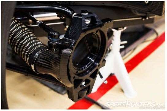
Fig 1.2: Agera Rs front brake
2 Methods
2.1 Possible methods discussion
When finding the solution of a quantitative engineering problem, there are only three main methods –
numerical methods, analytical methods and experimental methods. Many engineering problems can be
solved with analytical method, this method is generally used at some stage in most projects. However, if it
is necessary to make assumptions and simplifications to the problem to be able to calculate, it can normally
provide valuable solutions.
Numerical simulations are run on computers which perform a huge number of calculations and give an
approximate solution, which is very good if the calculation is detailed enough. The numerical approach
makes it possible to study the subject in detail and monitor the properties of interest.
The experimental approach is often the most accurate since few assumptions and simplifications are needed.
However, in some cases it may be difficult to accurately measure physical properties with good precision.
In such cases it is hard to interpret the results and draw conclusions for further development. An
experimental approach is usually more expensive and requires more resources, than analytical or numerical
methods do.
2.2 Method used in this paper
This project involves heat dissipation rate and air flow around rotor disc, therefore the analytical approach
is not applicable.
Whereas experimental approach would be possible but it requires a great number of prototypes, expensive
test equipment and the cost to execution of many tests. And it would also be difficult to measure properties
like temperature and velocity of air in detail. Hence experimental approach is not feasible for this project.
The numerical approach was chosen for this project because it is only feasible method available. This
project only focusses on the finite element analysis (FEA) of disc brake.
JETIR2202039 Journal of Emerging Technologies and Innovative Research (JETIR) www.jetir.org a312© 2022 JETIR February 2022, Volume 9, Issue 2 www.jetir.org (ISSN-2349-5162)
3 Theoretical frameworks
3.1 Brake System
Disc brakes are mostly used in contemporary cars. The brake consists of a disc (rotor) which is coupled to
the wheel and stationary brake caliper to squeeze pairs of pads against the disc to create friction. This action
slows the rotation of shaft, either to reduce its rotational speed or to hold it stationary. The brakes on
passenger cars are actuated with hydraulics using a brake fluid (different from other fluid) in order to avoid
vaporization at high temperatures.
Fig 3.1: Hydraulic disc brake system
3.2 Brake energy
Mechanical brakes are transforming kinetic energy to heat energy and usually an insignificant amount of
energy is also dissipated as sound. During a brake event, the brake caliper pistons press the brake pads
against the surfaces of the rotating brake disc, resulting in friction between the pads and the disc. The
friction force results in a counteracting (braking) torque due to the distance from the rotational centre. Heat
is generated due to the friction in the sliding contact between the pads and the disc. The amount of energy
converted to heat in the brakes during a braking event can be calculated using the formulas below.
The kinetic energy absorbed during the braking event can be calculated using formula
Apart from the braking deceleration, the car is also decelerated by the aerodynamic drag force, formula
There are also other losses, like rolling resistance, but these are negligible in this case. In order to get the
work done by the drag force, it is multiplied by the distance in the form of vdt. And since velocity is not
constant during the braking event, it must be defined as a function of time v(t). The work due to drag are
obtained by integrating over the duration of the braking event.
The total energy (or work) that the mechanical brakes convert to mainly heat, can be calculated by
subtracting the drag energy from the kinetic energy
JETIR2202039 Journal of Emerging Technologies and Innovative Research (JETIR) www.jetir.org a313© 2022 JETIR February 2022, Volume 9, Issue 2 www.jetir.org (ISSN-2349-5162)
The amount of energy absorbed by the front brakes is proportional to the load on the front axle if the tyre
friction coefficient is the same front and rear. With the assumption that the car is braked at the limit of lock
up, that there is negligible aerodynamic downforce and that the aerodynamic drag force acts through the
CG, the load proportion on the front axle can be calculated as below
Fig 3.2: Free body diagram of a braking car
The inertia force ma is acting in the opposite direction of the acceleration.
Load proportion front axle
So, the amount of energy that is converted to heat in one front brake can be calculated with formula
3.3 Temperature calculation
If heat energy is added to a material, its temperature increases. The magnitude of the temperature raise
depends on the material property specific heat capacity (c) and the mass of the object. The temperature
change is calculated with the formula
JETIR2202039 Journal of Emerging Technologies and Innovative Research (JETIR) www.jetir.org a314© 2022 JETIR February 2022, Volume 9, Issue 2 www.jetir.org (ISSN-2349-5162)
Where, ΔT = Temperature change [K]
Q = Heat energy transferred [J]
c = Specific heat capacity
m = mass [kg]
3.4 Modes of heat transfer
Heat transfer s generally occur in three ways – Conduction, Convection and Radiation. Let see how heat
is dissipated in disc brake.
Fig 3.3 Brake heat transfer modes
3.4.1 Conduction
Conduction is the heat transfer process that takes place in solids and through physical contact between
substances. This heat transfer process takes place at a molecular level, the heat causes the atoms to vibrate
and collide with neighbouring atoms resulting in a domino effect that propagates throughout the substance.
Solids and in particular metals are good heat conductors due to their closely packed atoms while gases are
less conductive due to larger distances between molecules. The empirical formula for conduction also
known as Fourier's Law
where
q = heat energy transferred per unit time [W]
k = thermal conductivity of the material
A = surface area [m2]
ΔT = temperature difference over the material thickness. [K]
dx = thickness of the material [m]
JETIR2202039 Journal of Emerging Technologies and Innovative Research (JETIR) www.jetir.org a315© 2022 JETIR February 2022, Volume 9, Issue 2 www.jetir.org (ISSN-2349-5162)
3.4.2 Convection
Convection is the process by which heat is transferred by movement of a heated fluid such as air or water.
If the fluid movement occurs due to density variations caused by local temperature gradients in the fluid, it
is called natural or free convection. This is the way a heating element normally works in a room, the air
close to the element is heated (through conduction) and then that hot air rises due to it being lighter than
the surrounding air. This air motion helps to dissipate the heat in the room and continuously pass cold air
over the heating element. If the fluid motion is caused by an external force such as wind or a fan it is called
forced or assisted convection. Forced convection is in many applications used to increase the rate of heat
exchange.
The empirical formula for convection, also known as Newton's Law of Cooling
where
q = heat energy transferred per unit time [W]
hc = convective heat transfer coefficient
A = surface area [m2]
ΔT = temperature difference between the surface and the bulk fluid [K]
3.4.3 Radiation
Radiation is a heat transfer mode that consists of electromagnetic waves (similar to light) that are emitted
by the heated object. Unlike conduction and convection which needs a medium to transport the heat energy,
radiation also occurs in vacuum and can travel vast distances. Air and many other gases are practically
transparent for radiation, which means that little or no energy is absorbed by it. The electromagnetic waves
emitted during normal cooling are in the so-called infrared spectrum, which is invisible for the human eye.
4 Component Description
4.1 Brake disc
Fig 4.1: Front brakes, inside (left) and outside (right)
The front brake discs are made of Carbon fibre-reinforced silicon carbide (C/SiC) and are 397 mm in
diameter and has a thickness of 40 mm. Ventilation channels are provided in disc with same number of
inlet and outside. The brake discs also have 90 cross drilled (axial) 3 mm holes that pass through the
JETIR2202039 Journal of Emerging Technologies and Innovative Research (JETIR) www.jetir.org a316© 2022 JETIR February 2022, Volume 9, Issue 2 www.jetir.org (ISSN-2349-5162)
ventilation channels. The disc is mounted to its stainless centrepiece with a floating design, which allows
the disc to move a small distance in the axial direction and expand radially while it is kept centred about
the rotational axis, between the bolts holding the stainless centrepiece to the disc there are axial gaps
approximately 2 mm wide
4.2 Brake Pads
The brake pads are of a conventional design, with a steel back plate to which the friction material is bonded.
The friction material has low thermal conductivity compared to the brake disc material
Fig 4.2: Front brake pad (hella.com)
4.3 Brake Caliper
The brake calipers are of the fixed type with a total of six pistons, three on each side of the disc. The caliper
body is milled from aluminium in two pieces which are bolted together. The pistons are made of a ceramic
material in order to conduct less heat into the brake fluid.
Fig 4.3: Front brake caliper (edrmagazine.eu)
JETIR2202039 Journal of Emerging Technologies and Innovative Research (JETIR) www.jetir.org a317© 2022 JETIR February 2022, Volume 9, Issue 2 www.jetir.org (ISSN-2349-5162)
4.4 Wheel Rim
The Koenigsegg Agera RS wheel rims are made of carbon fibre to reduce the unsprang weight. They are
19 inch in diameter.
Fig 4.4: Agera RS wheel rim (AutoEvolution)
4.5 Brake Duct
Brake ducts work by channelling air from a high-pressure source (usually the front surface of the car) to
the brake rotor. The air introduced by the brake ducts is much cooler than the brakes, and the airflow
continuously moves hot air away and allows the brakes to shed heat at a faster rate.
A cheap, light, and effective brake cooling system can be made by routing air from a high-pressure area on
the body into the centre of each rotor. The goal is to increase the air flow rate through the brake rotor vanes,
which will cool the rotors faster.
Fig 4.5: Brake cooling duct (koenigsegg.com)
JETIR2202039 Journal of Emerging Technologies and Innovative Research (JETIR) www.jetir.org a318© 2022 JETIR February 2022, Volume 9, Issue 2 www.jetir.org (ISSN-2349-5162)
5 Results
The majority of the results are presented in this section, a few more where simulated but are not included
in this report.
Result
1
Material Because of its high melting point, tungsten may be used as brake rotor material
(Tungsten) Melting point: 3,410 °C (6,152 °F)
Simulation Maximum Minimum Total Heat Directional
Conditions Temperature Temperature Flux Flux
200℃ 195.98℃ 28362W/m2 (max) 24687W/m2 (max)
3.9603W/m2 (min) -10686W/m2(min)
Comment The results are not satisfactory, but with combination of Gray cast iron gives better
results.
Result
2
Material Titanium alloys are potentially good candidate brake rotor materials with the
(Titanium) advantages of weight reduction and increased strength and corrosion resistance
compared with cast iron.
Simulation Maximum Minimum Total Heat Directional
Conditions Temperature Temperature Flux Flux
200℃ 188.87℃ 27816W/m2 (max) 23781W/m2(max)
1.0867W/m2 (min) -10330w/m2(min)
Comment Results are better than tungsten
JETIR2202039 Journal of Emerging Technologies and Innovative Research (JETIR) www.jetir.org a319© 2022 JETIR February 2022, Volume 9, Issue 2 www.jetir.org (ISSN-2349-5162)
Result
3
Material Gray iron is the most widely used brake rotor material in the industry owing to its
(Gray Cast superior thermal handling capacity, damping characteristics, and wear and cost
Iron) advantages.
Simulation Maximum Minimum Total Heat Directional
Conditions Temperature Temperature Flux Flux
200℃ 187.16℃ 27409W/m2 (max) 23562W/m2(max)
1.0888W/m2 (min) -10250w/m2(min)
Comment Cast iron is very cheap to produce and produces very good friction coefficients but
it is also fragile, it is not compatible with many modern pad materials
6 Conclusion
It can be concluded that improving the cooling was more difficult than anticipated. Gray cast iron is very
cheap to produce and produces very good friction coefficients but it is also fragile, it is not compatible
with many modern pad materials.
Titanium alloys are potentially good candidate brake rotor materials with the advantages of weight
reduction and increased strength and corrosion resistance compared with cast iron. Titanium may be used
as rotor material but it is very costly, although titanium has good thermal properties, high strength to weight
and corrosion resistance, this makes titanium an ideal material. But due to cost reasons we are unable to
use it as brake rotor material.
Most of the modern cars, brake rotors are made from either cast iron or carbon ceramic materials. Tungsten
carbide is a dense, metal like substance, light gray with a bluish tinge, that decomposes, rather than
melts, at 2,600° C (4,700° F). It is prepared by heating powdered tungsten with carbon black in the presence
of hydrogen at 1,400°–1,600° C (2,550°–2,900° F).
Tungsten carbide has high tendency of heat dissipation which makes it perfect for brake rotor material.
Because so little of the rotor actually wears throughout its service life, it produces around 90 percent less
brake dust and due to this life of disc increases around 30 percent. The tungsten carbide coating also allows
the rotors to maintain cooler temperatures after repeated hard stops.
References
[1] Anant Nemade1 , Samir Telang2 , Arvind Chel3 , Geetanjali Kaushik - thermal behaviour of disc
braking system: a review
[2] Paweł Szymański1 *, Dorota Czarnecka-Komorowska1 , Katarzyna Gawdzińska2 Aleksandra Trubas3 , Ewelina
Kostecka2 - a review of composite materials used in brake disc pad manufacturing process
JETIR2202039 Journal of Emerging Technologies and Innovative Research (JETIR) www.jetir.org a320© 2022 JETIR February 2022, Volume 9, Issue 2 www.jetir.org (ISSN-2349-5162) [3] Arne Lindgren - Development of Brake Cooling [4] Manekari V, Raju JG.Design and analysis of ventilated and slotted disc brake IJRATS 2019. E-ISSN:2321-9637, www.ijrat.org. [5] Wei L, Choy YS, Cheung CS. A study of brake contact pairs under different friction conditions with respect to characteristics of brake pad surface, Journal of Tribology International, Elsevier 2019:99-110. DOI: org/10.1016/j.triboint.2019.05.016. [6] Laguna-Camacho JR, Juárez-Morales G, Calderón-Ramón C, Velázquez-Martínez V, Hernández-Romero I, MéndezMéndez JV. A study of the wear mechanism of disc and shoe brake pads, Journal Engineering Failure Analysis 2015;56:348-359 DOI: http://dx.doi.org/10.1016/j.engfailanal.2015.01.004 [7] Clay Mathematics Institute. (2000). Navier–Stokes Equation. Retrieved April 10, 2016, from Clay Mathematics Institute: http://www.claymath.org/millennium-problems/navier%E2%80%93stokesequation JETIR2202039 Journal of Emerging Technologies and Innovative Research (JETIR) www.jetir.org a321
You can also read