Eve Single Pro-line DE-Manual - Besserladen.de
←
→
Page content transcription
If your browser does not render page correctly, please read the page content below
–
Eve Single Pro-line DE
Manual

Pro-line DE

2
EVE SINGLE PRO-LINE DE

                             OUTSIDE
MODEL WITH CHARGING CABLE/               MODEL WITH SOCKET/
  MODELL MIT LADEKABEL                  MODELL MIT STECKDOSE

                              1                                1

                              2                                2

4                                  4

                              3                                3

            INSIDE/                           BOTTOM/
          INNENSEITE                         UNTERSEITE
    11                       11

    5

    6
                             10a
    10a
                                   13
                             9
    11

                             11

                             7

                             8
                                   14                          15
    12

                                   17                          18
                             10b
                                                               16
    11                       11

    10a

                                                                    3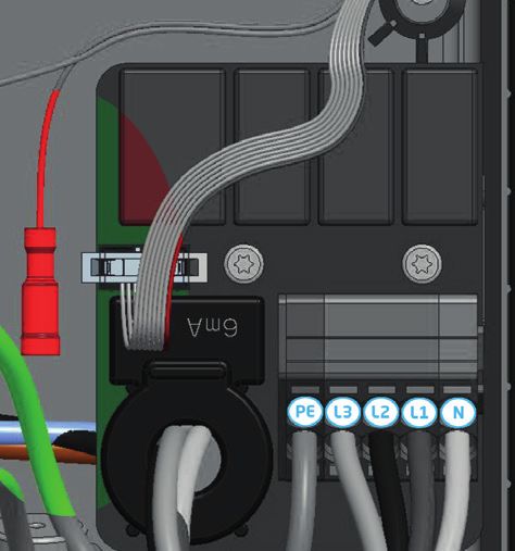
4
ENGLISH
Step-by-step Eve Single
Pro-line DE installation and

–
commissioning
Congratulations on your purchase of an Alfen charging
station for electric vehicles!
To ensure safe installation, and full utilisation, of all advanced features of your charging
station, we recommend that you read this manual carefully and save it for future reference.

While we have done our utmost to provide you with a complete and comprehensive manual,
it may occasionally be subject to updates and content improvement. The latest version will
always be available for download at www.alfen.com.

                                                                                                     5
TABLE OF CONTENTS

          1       Safety and usage instructions                 7    5.3     Register your ICU EZ account                     26
          1.1     Purpose and intended audience                 7    5.4     Managing settings                                26
          1.2     General safety                                7    5.5     Register your charging station to your
          1.3     Disclaimer                                    7            own management system                            26
          1.4     Copyright
ENGLISH

                                                                     Appendices
          2      Product                                        8    Appendix A: Error codes and problem-solving              27
          2.1    The charging station                           8    Appendix B: Default selections for optional
          2.2    User interface                                 9                factory settings                             29
          2.2.1  Status indications on Eve Single Pro-line           Waste Electrical and electronic equipment (WEEE)         34
                 DE models                                      9
          2.2.2 Status indicator symbols                        9
          2.3    Operation                                      10   DECLARATION OF CONFORMITY
          2.4    Eichrecht                                      11   Manufacturer information:
          2.5    Access control for local authorisation              Alfen ICU B.V.
                 (RFID, only Pro-line models)                   12   Hefbrugweg 28
          2.5.1 Installing the Master Key                       12   1332 AP Almere
          2.5.2 Adding and removing passes in                        The Netherlands
                 the local database                             12
          2.5.3 Removing the Master Key                         12   Declares that the charging station of the type Alfen Eve
          2.6    Technical specifications                       13   Single Pro-line DE, to which this declaration applies,
          2.6.1 Eve Single Pro-line DE models                   13   complies with:
          2.6.2 The Eve Single Pro-line DE overview             13
          2.6.3 Eve Single Pro-line DE specifications           13   1) The provisions of the low voltage directive 2014/35/EU
          2.6.4 Communication and protocols                     13   2) The provisions of the EMC guideline 2014/30/EU
          2.6.5 Communications security                         14   3) The following harmonised standards:
          2.6.6 General product spacifications                  14       IEC 61851-1 ed. 3 (2017)- Electric vehicle conductive
          2.6.7 Available memory                                15       charging system - General requirements, on national
          2.6.8 Use conditions                                  15       level implemented under DIN-EN 61851-1.
          2.6.9 Casing                                          16   4) Eichrecht certified by CSA Group Bayern GmbH (1948)
          2.6.10 Installation instructions                      16       Module-B : DE MTP 19 B 004 M
          2.6.11 External protection according to                        Module-D : DE MTP 19 D 003 MI-003
                 EV/ZE-Ready                                    17   • Mess- und Eichgesetzes vom 25.07.2013 (BGBl. I S.
          2.7    Optional factory settings                      17      2722), zuletzt geändert durch Artikel 1 des Gesetzes
          2.8    Accessories                                    18      vom 11.04.2016 (BGBl. I S. 718)
                                                                     • Mess- und Eichverordnung vom 11.12.2014 (BGBl. I S.
          3       Assembly and connecting                       19      2010), zuletzt geändert durch Artikel 10 der Verordnung
          3.1     Installing and connecting                     19      vom 30.04.2019 (BGBl. I S. 2034).
          3.2     Assembly and installation requirements        20   • REA-Dokument 6-A „Regeln und Erkenntnisse des
          3.3     Mechanical installation                       20      Regelermittlungsausschusses nach § 46 des Mess- und
          3.4     Electrical installation                       22      Eichgesetzes für Messgeräte und Zusatzeinrichtungen im
                                                                        Anwendungsbereich der E-Mobilität“ Stand: 16. März 2017.
          4       Commissioning the charging station            23   • PTB-Anforderungen an elektronische und software-ge-
          4.1     Safety instructions before use                23      steuerte Messgeräte und Zusatzeinrichtungen für
          4.2     Commissioning Eve single Pro-line DE models   23      Elektrizität, Gas, Wasser und Wärme [PTB-A 50.7] vom
          4.3     Configuring the charging station with                 April 2002.
                  Service Installer (application)               23
          4.3.1   Preparation                                   23   All mentioned products are labelled with the CE mark.
          4.3.2   Using the Service Installer application       24
          4.3.3   Changing language settings                    24   Almere, The Netherlands, 3 februari 2020.
          4.4     Activate functionality with the
                  Service Installer application                 24

          5       Connectivity                                  25
          5.1     Management systems                            25   Ir. M. Roeleveld
          5.2     Setting up a connection                       25   CEO
          5.2.1   Wireless connection                           25
          5.2.2   UTP (Ethernet) connection                     25
     6                                                                     Eve Single Pro-line DE manual | Version 1.0 | February 2020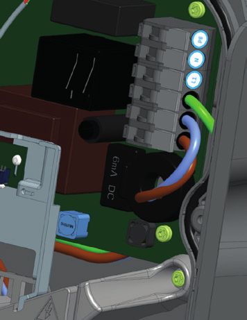
1. SAFETY AND USAGE INSTRUCTIONS

1.1 Purpose and intended audience                                  1.3 Disclaimer
The Alfen Charging station (the “Product”) is intended             This manual applies to the Product equipped with firmware
exclusively for charging electric vehicles and, when installed     version 4.7.0 or higher.
correctly, may be used by untrained individuals.
                                                                   This document has been subjected to rigorous technical

                                                                                                                                    ENGLISH
Installation, commissioning and maintenance of this                review before being published. It is revised at regular
Product may only be performed by a qualified electrician           intervals, and any modifications and amendments are
(Alfen certified partner). It is essential that the qualified      included in the subsequent issues. The content of this
technician has:                                                    document has been compiled for information purposes only.

• Expertise on all relevant general and specific rules             Although Alfen has made its best efforts to keep the
  regarding safety and incident prevention                         document as precise and up-to-date as possible, Alfen shall
• Comprehensive knowledge of applicable electrical                 not assume any liability for defects and damage which
  regulations.                                                     results from the use of the information contained herein.
• The ability to identify risks and avoid potential hazards.
• Received and read these installation and operation               In no event will Alfen be liable for direct, indirect, special
  instructions.                                                    or consequential damages (incl. loss of profits) resulting
                                                                   from any errors or omissions in this manual. All obligations
1.2 General safety                                                 of Alfen are stated in the relevant contractual agreements.
                                                                   Alfen reserves the right to revise this document from time
        DANGER!                                                    to time.
These safety instructions are important to ensure safe
operation. Failure to comply with them in accordance with          Any deviation to the Products including, but not limited
general electrical safety regulations could result in a risk of    to, customer-specific modifications (like customisation
electrical shock, fire and/or life threatening injury.             by placing stickers, SIM cards or the usage of different
                                                                   colours), hereafter referred to as ‘Customisation’, can alter
Using this product is expressly prohibited in the following        the final product experience, product appearance, product
situations:                                                        quality and/or product lifespan. Alfen is not liable for any
• In the vicinity of explosive or highly flammable                 damage to, or caused by, the product (including applied
   substances.                                                     Customisation) if this damage is caused by this applied
• If the product is located in or close to water.                  Customisation. Contact your dealer for more information on
• If the product or its individual components are damaged.         Customisation versus the default product.
• Usage by children or individuals not able to properly
   assess the risks associated with using this product.            1.4 Copyright
                                                                   Copyright © Alfen N.V. 2020. All rights reserved. The
Alfen ICU B.V. (“Alfen”) shall not be liable in any way, for any   disclosure, duplication, distribution and editing of this
kind of damage, and all warranties on both the product and         document, or utilization and communication of the content
accessories shall become void where:                               are not permitted, unless authorized in writing. All rights,
• The Products have been subject to misuse, faulty                 including rights created by patent grant or registration of a
   installation or maintenance; or                                 utility model or a design, are reserved.
• The Products have been dissembled, modified or
   repaired; or
• The manuals, use conditions and maintenance
   instructions which are applicable for (parts) of the
   Products or have been provided by Alfen are not
   complied with; or
• The Products are used in the vicinity of explosive or
   highly flammable substances or in or near to water; or
• In case of normal wear and tear; or
• There is a failure of the distribution network; or
• There is a force majeure situation, or the defect is
   otherwise caused from the outside.

More extensive safety information is available in the
relevant sections of this document.

Eve Single Pro-line DE manual | Version 1.0 | February 2020                                                                         7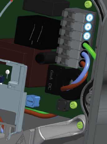
2. PRODUCT
2.1 The charging station
On page 3 of this manual, you will find the images of the Eve Single Pro-line DE product line. In this chapter, you will find
more information on the contents of these charging stations and how they can be used to charge your vehicle.
ENGLISH
Eve Single Pro-line DE (page 3)
Outside
1 Colour display
2 RFID pass reader
3 Type 2 socket or plug holder
4 Energy meter viewing window
Inside
5 UTP (Ethernet) connector
6 RJ11 connector
7 SIM card holder
8 Terminal block for the power cable
9 Clamps for outbound charging cable (model without socket outlet)
10 a. Screws for wall-mounting frame
10 b. Screws for wall-mounting frame with earth connection
11 Screws for front cover
12 Eichrecht compliant electricity meter
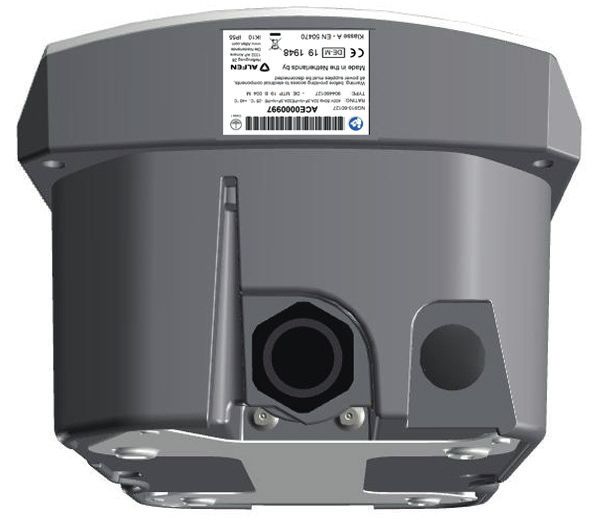
Bottom
13 Identification label
14 Cable gland for the power cable
15 Cable gland for charging cable
16 Wall-mounting frame
17 Grommet for UTP cable/Ethernet cable
18 Grommet for P1 cable
Identification label
The identification label 13 found on the bottom of the charging station specifies elements such as:
• Model, production date and serial number.
• Technical specification number.
• Article number and maximum charging current.
When contacting Alfen, always have your serial number available to facilitate quick support.
8 Eve Single Pro-line DE manual | Version 1.0 | February 2020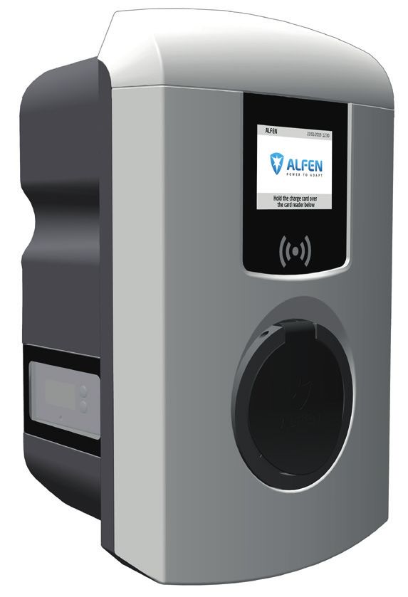
2. PRODUCT

2.2 User interface
The Eve Single Pro-line DE has a colour display which informs the user on the progress of the charging by using status
indications.
2.2.1 Status indications on Eve Single Pro-line DE
models

                                                                                                                                                ENGLISH
General information on charging station
 1 The charging station ID: Identification is determined by
                                                                               ALFEN 1             2 22/01/2019 12:30

    the reseller or operator of the central management                              Fahrzeug wird geladen      3
    system. Use this ID to convey to a helpdesk for which                                               22kW      4
    charging station you need support.
 2 Date and time: these are set through a central                                  5    18.1kW
    managemant system (automatically) or during                                                                   22.67kWh             7
                                                                                                 6
    installation, using the Service Installer application.
                                                                                                       01:23h      8
    If the product does not have a current time, this field is                     akux Imzb fq2u rt7d qoly 7ipe 6ez4 ke2b nevf b3I3
                                                                                                                                       9

    hidden.                                                                              Um Laden zu stoppen                   10          11
                                                                                          Ladekabel abziehen
Status and information screen
                                                                         Figure 1: Display of Eve Single Pro-line DE during charging with
Status and information screen: the charging station                      type 2 Socket
informs the user of its current status and provides the user
with a response to the actions performed. The following
information is available:
 3 Status information.

 4 Maximum charging capacity of the outlet.

 5 Current charging capacity to the connected

    vehicle.
 6 Status indicator (refer to paragraph 2.2.2).

 7 Energy picked up during the current transaction.

 8 Duration of the current transaction.

Instruction field
  9 During a charging session the public key is shown on

    the display.
 10 User instructions will be displayed in this location.

    Where an error occurs, an error code and instruction will
    be shown (see Appendix A for more information).
 11 A full progress bar indicates the necessary steps are

    completed and charging will start.

2.2.2 Status indicator symbols

    Charge pass accepted,                              Communicating with vehicle                         Warning, notification with
      cable connected                                     or charging complete                                   error code

               --kW

        --kW            --.--kWh

               --.--h

    Charging transaction                               Error, notification with error
 active, with charging speed                                        code
          indication

Eve Single Pro-line DE manual | Version 1.0 | February 2020                                                                                     9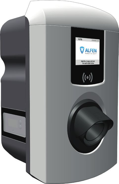
2. PRODUCT

          2.3 Operation
          Specific user actions are presented in a sequence that clearly shows the progress and corresponding status indications.
          The first steps can be conducted in any sequence. Upon detecting a charging cable or charge pass, all Eve Single Pro-line DE
          products will show the green check mark symbol. The light blue (cyan) hourglass symbol will only be displayed if and when
          a connection between the vehicle and charging station is established. During charging the status indicator will show the
ENGLISH

          charging transaction is active.

                                    Operation Plug & Charge – Authorisation without a charge pass
            Start

                                    1                        2                        3

                                                                                                  --kW

          Pro-line                                                                         --kW            --.--kWh

                                                                                                  --.--h

            Stop

                                    1                        2                        3

          Pro-line

                               RFID - Charging station with user authorisation
            Start

                                1                        2                        3                                   4

                                                                                                                                 --kW

          Pro-line                                                                                                        --kW            --.--kWh

                                                                                                                                 --.--h

            Stop

                                1                        2                        3                                   4

          Pro-line

  10                                                                            Eve Single Pro-line DE manual | Version 1.0 | February 2020
2. PRODUCT
2.4 Eichrecht
The Eve Single Pro-line DE charging stations are Mess- and Eichrecht compliant. The charge stations are outfitted with
measuring equipment to ensure the meter values can be verified and validated by the end user. According to the Eichrecht
law and regulation the operator must provide the correct value on the energy meter at the time of Invoicing.
In addition the charging station will show how much has been charged at the end of a charging session.
ENGLISH
A digital signature protects the meter values according to the calibration law and regulations. With this digital signature,
the end user can check the correct kWh counter value on the Eichrecht compliant electricity meter. The Eichrecht compliant
energy meter is located on the side of the charging station.
Eichrecht Eichrecht
compliant compliant
energy energy
meter meter
Figure 2: The Eve Single Pro-line DE with the Eichrecht compliant electricity meter on the side
During a charging session the public key and the kWh value are shown on the measurement unit. The measurement unit is
illuminated making it readable at all time.
Figure 3: The Eichrecht compliant energy meter display with kWh value and public key
REMARK
For more information and operation of the Eichrecht feature please refer to the 'Eichrecht Benutzerhandbuch Anhang
Eichrecht-konforme EV-Ladelösung'-Addendum to this manual delivered with your product.
Eve Single Pro-line DE manual | Version 1.0 | February 2020 112. PRODUCT
2.5 Access control for local authorisation (RFID)
To control local user access to an Alfen Eve Single Pro-line DE charging station, you need to install an RFID pass as the
'Master key'. With this Master Key, you can determine who can use your charging station.
REMARK
ENGLISH
Your charging station must be configured correctly in order to accept Master Keys. For stand-alone charging stations this
functionality is automatically ON. If the charging station is delivered with a pre-programmed management system, this
functionality will be OFF.
2.5.1. Installing the Master Key
A Master Key can be easily installed using the following steps:
1 Select an RFID pass like the included Alfen pass, that complies with the specifications mentioned in paragraph 2.6.3.
2 Hold the RFID pass in front of the pass reader for 10 seconds. The charging station does not recognise the pass and
will give a warning first. You can ignore this.
3 After 10 seconds, the RFID pass will be registered as the Master key. The following icon appears on the screen:
NOTICE!
The Master Key cannot be used for charging. It is only used
for access control of the charging station.
The charging station will only recognise one RFID pass as the Master Key.
2.5.2 Adding and removing passes in the local database
Once the Master Key is registered, it can be used to add or remove charging passes from the local database. For every pass
held in front of the charging station, the station will give a sound signal. Follow the on-screen instructions to manage
access control:
Hold the Master Key in front Hold the charge pass that you Hold the charge pass that you
of the pass reader want to add in front of the pass want to remove in front of the
reader pass reader
Display
Supporting text Master Key held in front of Pass added Pass removed
on display reader
Add or remove charge passes
If you add or remove a charge pass accidently, immediately hold it in front of the pass reader to undo the action.
To close the database, hold the Master Key in front of the pass reader once more.
REMARK
To prevent the local database from being 'open' to access control, the menu will close automatically if no card has been
detected or removed after 10 seconds. The symbol will disappear from the display.
2.5.3 Removing the Master Key
A Master Key can only be removed using the Service Installer application. If necessary, you can ask for help from one of our
technicians. This might, however, incur costs. Therefore, always keep the Master Key in a safe location. More information on
the use of the Service Installer application can be found in paragraph 4.3.2.
12 Eve Single Pro-line DE manual | Version 1.0 | February 20202. PRODUCT
2.6 Technical specifications
2.6.1 Eve Single Pro-line DE models
Models
Pro-line DE
ENGLISH
Eve Single Pro-line DE, 3 phase, display, type 2 socket 904460123 NG910-60123
Eve Single Pro-line DE, 3 phase, display,
904460127 NG910-60127
charging cable (5 or 8 meter, see 'Accessories')
2.6.2 The Eve Single Pro-line DE overview
3 phase •
RFID pass reader •
RGB LED -
Display •
Energy meter MID certified, encrypted data transport
Eichrecht support •
Max. 6mA DC detection •
Residual Current Breakers -
Short-circuit protection -
Mobile network communication •
Ethernet/LAN network connection •
2.6.3 Eve Single Pro-line DE specifications
Plug & Charge authorisation
RFID authorisation
Operation
Central system
Third-party apps
Display 3.5" TFT colour display, 320 x 240 pixels
RFID (NFC) ISO/IEC 14443A/B, MiFare Classic 13.56 MHz, DESFire
RFID pass reader
Maximum length: 7 bytes
Mobile network possibilities GPRS
Energy meter MID certified & Eichrecht compliant
Status indication Integrated in the display
Access Locations with restricted access
Locations with non-restricted access
2.6.4 Communication and protocols
Controller Central unit for charging currents and communication
Vehicle communication Mode 3 in accordance with IEC 61851-1 ed. 3 (2017)
Internet/networking possibilities Mobile network communication, Ethernet/LAN
Communication protocol Central System OCPP 1.5 (JSON), OCPP 1.6 (JSON)
OCPP
Supported RJ45 protocols
TCP/IP
DSMR 4.0-4.2 and SMR5.0 (P1 port)
Supported RJ11 protocols
I/O for supporting external relay
Modbus (Master/slave) TCP/IP
Eve Single Pro-line DE manual | Version 1.0 | February 2020 132. PRODUCT
2.6.5 Communications security
SIM card Mini SIM card
APN username and password
Central System authentication TLS 1.2 x509 2048/4096 bit root certificate
ENGLISH
EVSE authentication HTTP Basic authentication, with or without TLS
Remote console access (SSH, telnet) Not supported
Diagnostic files Encryption: AES 128 bit
Firmware update files Encrypted and digitally signed
Encryption: SHA256 hash (pkcs1/PSS padding with 2048 RSA key)
Signature: RSA public key 2048 bit
EVSE Interal Flash AES 128 bit (erased when read)
Root certificate Installed in the factory, update through UpdateFirmwire file
For more information on the implementation of information security in Alfen Charging Equipment, you can contact
ace.salessupport@alfen.com
2.6.6 General product specifications
Number of outlets 1
Types of outlets Fixed cable
Type 2 socket, in accordance with IE62196-2
Supported power systems TN-C, TN-C-S, TT, IT grid
Nominal output voltage (+/- 10%) 400VAC (3x230VAC)
Maximum design current 32A per phase
Maximum design power 22kW
Connection clamps Cable gland, clamping range for 14-25.5mm cable thickness
Cable clamps on input filter block. Range:
• 10mm 2 per vein: solid (VD) wire
• Max. 6mm 2 per vein: stranded (VDS) wire with ferrules
Activation relay Integrated, simultaneous activation
Extra safety relay in series
Residual current protection Integrated 6mA DC leakage current detection
Response time: 1-5 seconds
Overcurrent protection Integrated in firmware; shut down at: 105% after 1,000 seconds;
110% after 100 seconds; 120% after 10 seconds; 150% after 2 seconds.
Available in- and outputs RJ45 (Ethernet/LAN)
RJ11 (active load balancing)
NOTICE!
Alfen Eve Single charge stations contain a 6mA DC detector that protects the earth leakage circuit breaker against DC leak-
age currents. The DC detector prevents type A earth leakage circuit breakers from becoming 'blind' to dangerous leakage
currents. The charging station will respond well in advance of any dangerous situation (6mA vs 30mA). Instead of jumping
the earth leakage circuit breakers, the charging station will stop the charging process in a controlled manner if leakage
currents are detected. After a time-out, and provided that the 6mA leakage current is no longer measured, the charging
process will be restarted. Three restarts are possible before the charging process is stopped permanently and an error code
is displayed. This function does not, nor will it ever, replace an earth leakage circuit breaker and cannot be tested as such
by the installer. If legislation and regulations require a type B earth leakage circuit breaker to be installed, regardless of the
presence of a 6mA DC detector, this can be installed without any problems.
14 Eve Single Pro-line DE manual | Version 1.0 | February 20202. PRODUCT
2.6.7 Available memory
Charge passes Local list: approx. 800 charge passes (via the Backend)
White list: approx. 1,200 charge passes (local)
Transaction database Approx. 1,500 transactions (of 4u with 15min Wh-metering values)
ENGLISH
Logging for diagnostics Approx. 45,000 lines
2.6.8 User circumstances
Operating temperature -25°C - 40°C
Relative atmospheric humidity 5 - 95 %
Electrical safety class I
Degree of protection (casing) IP55
IK protection (mechanical impact) IK10
Stand-by use Pro-line: approx. 3.9 – 4.1W
Environmental conditions • Indoor use
• Outdoor use
Electromechanical environmental E2 according to the Measuring Instruments Directive (2014/32/EG)
conditions
Mechanical environmental conditions M1 according to the Measuring Instruments Directive (2014/32/EG)
NOTICE!
Where products are exposed to the elements, the case can be subject to gradual aging of the material, which can result in
product discolouration over time. Therefore, wherever possible, place the product in a sheltered place to optimise the life
of the materials.
NOTICE!
The operating temperature assumes the ambient temperature of a product delivered in the default casing colour 'RAL9016'.
Direct exposure to sunlight may have an adverse effect on the temperature range.
The ambient temperatures in the table above refer to a to decrease the internal temperature. This stabilises the
product in its default casing, colour RAL9016. Other internal temperature and makes it less likely that a
(darker) colours may have an adverse effect on the product. transaction will be unexpectedly paused.
If the product is exposed to lower or higher temperatures, If the product is directly exposed to sunlight, the
continuous operation cannot be guaranteed. automated temperature management may automatically
If temperatures exceed the maximum values, the charging start below the maximum ambient temperature.
station will automatically decrease the charging current
Eve Single Pro-line DE manual | Version 1.0 | February 2020 152. PRODUCT
2.6.9 Casing
Type Wall-mounted unit
Mounting options Wall mounting or mounting post (accessory)
Material Polycarbonate, UV resistant and flame retardant
ENGLISH
Colour RAL9016 (Traffic White): front side
RAL 7043 (Traffic Grey B): rear
Locking Torx T20 screws
Dimensions Eve Single Pro-line DE Socket (H x W x D)
Casing 370 x 240 x 175mm
Packaging 470 x 320 x 290mm
Dimensions Eve Single Pro-line DE Fixed (H x W x D)
Casing 470 x 320 x 290mm
Packaging 470 x 320 x 410mm
Weight
Casing Approx. 4,5 kg
Total, incl. packaging Approx. 5 kg
2.6.10 Installation instructions
NOTICE!
Your installation must comply with the standards and regulations of the location (country) where it is installed. The tables
below are recommended and based on the proper practical functioning of the charging stations, provided all necessary
conditions are met.
Printing errors are expressly reserved
Input: minimal
recommended cable 3-phase 11kW charging, 16A per phase: 5 x 4 mm2.
diameters (based on 3-phase 22kW charging, 32A per phase: 5 x 6 mm2.
assumed max. 50m
cable length)
Short-circuit protection With breaker circuits: With fuses:
3-phase 16A (11kW): 1 x 20A, 3P, type B or C 3-phase 16A (11kW): 3 x 20A gG
3-phase 32A (22kW): 1 x 40A, 3P, type B or C 3-phase 32A (22kW): 3 x 35A gG
Residual current Earth leakage circuit breakers: 30mA type A or B, 4P
protection (possibly 11kW charging: minimum 20A
i.c.w. circuit breakers) 22kW charging: 40A
For specific EV/ZE Ready requirements, see paragraph 2.6.11 for detailed specifications and
related requirements for the installation
Nominal input voltage • VL1-N: 230VAC (+/-10%)
• VL2-N: 230VAC (+/-10%)
• VL3-N: 230VAC (+/-10%)
• VL1-L2: 400VAC (+/-10%)
• VL1-L3: 400VAC (+/-10%)
• VL2-L3: 400VAC (+/-10%)
• VPE-N: ≈ 0VAC
Nominal frequency 50 Hz
Grounding TN system: PE cable
TT system: separately installed grounding electrode < 100 Ohm spreading resistance
IT system: connected to a shared reference (common earth) with other metal parts
Connection method Permanently connected
16 Eve Single Pro-line DE manual | Version 1.0 | February 20202. PRODUCT
2.6.11 External protection according to EV/ZE-Ready
NOTICE!
An installation in accordance with the EV/ZE Ready standard requires a high immunity type Residual Current Breaker
(if a type A RCD is applied). The RCD must comply with Level 4 specifications.
ENGLISH
IEC 61000-4-16 or IEC 61543
Level 3 Level 4
Frequency range Cont. test Vrms (V) Current (mA) Cont. test Vrms (V) Current (mA)
1 kHz - 1.5 kHz 1 6.6 3 20
1,5 kHz - 15 kHz 1 - 10 6.6 - 66 3 - 30 2 - 200
15 kHz - 150 kHz 10 66 30 200
2.7 Optional factory settings
Description Options
Authorisation Plug & Charge
RFID*
Maximum charging current 16A
32A*
Smart Charge options Off
(see Appendix B) Active load balancing*
Smart Charging Network*
Own logo in display Off (Alfen logo)
On (your own logo)
Languages supported English, Dutch, German, French, Spanish, Portuguese, Italian, Norwegian,
Swedish, Finnish
User availability if temporarily Accept all RFID passes
offline Only valid passes in database
Not available
Action if plug is released on vehicle Stop transactions and release the plug
side Pause charging until cable plugged back in
Choice of management system Stand alone, ICU Connect*, other options*
Communication through * GPRS, UTP/LAN, Autodetect
* Settings may incur additional costs.
The default settings are always displayed first.
Eve Single Pro-line DE manual | Version 1.0 | February 2020 172. PRODUCT
2.8 Accessories
Mounting pole Art. 803873036-ICU
Post dimensions (H x W x D) 1.180 x 60 x 120mm
Base plate 300 x 200 mm
ENGLISH
Wall-mount dimensions (H x W x D) 348 x 196 x 3mm
Material SAE 304 stainless steel,
Fine-structure powder coating
Colour RAL 7043 (Traffic Grey B)
Packaging (H x W x D) 1.200 x 340 x 220 mm
Weight 12 kg
Mounting Pole 2x Eve Single Pro-line DE Art. 803873037-ICU
Pole dimensions (H x W x D) 1.180 x 340 x 220mm
Material SAE 304 stainless steel,
Fine-structure powder coating
Colour RAL 7043 (Traffic Grey B)
Packaging (H x W x D) 1.200 x 340 x 220 mm
Weight 12 kg
Concrete base Art. 833829300-ICU
Dimensions (H x B x D) 570 x 350 x 220 mm
Weight 42 kg
Metal base Art. 803873065-ICU
Dimensions (H x B x D) 598 x 204 x 300
Weight 7.8 kg
Packaging (H x W x D) 50 x 295 x 620
Type 2 charging cable, 5m, 3 phase, up to 32A (22kW) Art. 203100304-ICU
Type 2 charging cable, 8m, 3 phase, up to 32A (22kW) Art. 203100305-ICU
Extra RFID card Art. 203120010-ICU
18 Eve Single Pro-line DE manual | Version 1.0 | February 20203. ASSEMBLY AND CONNECTING
Package contents Contents of the charging station package: Alfen Eve Single Pro-line DETM,
installation manual, wall-mounting frame, installation supplies and RFID charge
passes (depending on options selected)
1x 1x 1x 1x 1x 2x
ENGLISH
Eve Single Pro-line DE Wall-mounting This manual Quick Installation M25 x 1.5 M25 x 1.5
- With Socket frame Guide (For model (For model with
- With Fixed cable with socket) fixed cable)
4x 4x 4x 4x 6x 1x 1x 1x
Screw Plug 4.5-5 M8 nut M8 washer Torx screw Reduction Filler washer for Torx T20
5 x 50mm 8mm M4 x 8mm fitting the cable gland wrench
M32 x 1.5
3.1 Installing and connecting
Carefully read these instructions prior to installing the
DANGER!
The charging station contains electric components that
charging station. Alfen ICU B.V. is not liable for any
may still contain electrical charge after being disconnect-
consequential damage caused by usage of this manual.
ed. Wait at least 10 seconds after disconnection before
REMARK commencing work.
The installation must be carried out by a qualified
professional who has read this manual and works in
compliance with IEC 60364 standards. Neglecting this WARNING
may lead to severe injuries or hazardous situations while The adaptors or conversion adaptors are not allowed to be
working with electricity. used.
REMARK
This work may not be carried out during rain or if air WARNING
humidity exceeds 95%. Cord extension sets are not allowed to be used.
REMARK
A charging station must always be installed on a dedicated DANGER!
power circuit. The electric system must be entirely disconnected from
every power source prior to performing installation or
maintenance work!
DANGER!
Hazard of fatal injury if installed incorrectly!
Non-compliance with the installation and environment REMARK
requirements may lead to hazardous situations while The conditions at the specific location may influence the
working with electricity. installation requirements.
Eve Single Pro-line DE manual | Version 1.0 | February 2020 193. ASSEMBLY AND CONNECTING
3.2 Assembly and installation requirements • A temperature difference within 24 hours < 35 °C.
See the table in paragraphs 2.6.10 and 2.6.11 for • The recommended installation height is 80 - 120 cm
the safety options and necessary cable diameters from the ground to the bottom of the casing.
for a proper connection. • The charging port on the vehicle needs to be easy to
reach with the (attached) charging cable.
ENGLISH
Ensure that the following requirements for installing the • Ensure that the charging station is placed at a location
Eve Single Pro-line DE have been met: where users can use their charging cable (approx. 5 -
• The cable trajectory from the main distribution panel to 8 metres) without placing any tension on the cable.
the Eve Single Pro-line DE must be secured against • Prevent other drivers from being able to drive over
short-circuiting and overcurrent with: the cable.
- a B- or C-type circuit breaker (or other, in accordance • Prevent pedestrians from tripping over cables.
with local standards and regulations), or
- gG-type fuses (or other, in accordance with local 3.3 Mechanical installation
standards and regulations). Use the following tools and equipment to install the Eve
• The cable trajectory must be equipped with 30mA fault Single Pro-line DE:
current protection with a type A or B residual-current • Spirit level;
device (RCD). The RCD must be capable of withstanding • Impact drill with 8mm stone drill bit;
the maximum current the charging station can process • Cross-head screwdriver (PZ2);
(20A or 40A) • Cross-head screwdriver (PH4);
• The cable trajectory and the charging station are part of • Wire stripper;
a TN-S system; the equipment must be earthed at the • Torx T20 wrench (included);
main distributor or with an earth pin (TT). In an energy • 4x 5 x 50mm screw (included);
grid without neutral make sure that the station is • 6x M4 x 8mm screw (included);
properly earthed, one of the phases is used as a neutral • 4x plugs 4.5 - 5mm (included);
and that the voltage-levels of par. 2.6.10 are complied • 4x M8 washer (included);
with. • 4x M8 nut (included)
• The cable trajectory must be installed in accordance
with the usual local professional standards. Mounting post: Install the post with the concrete base
or metal base (accessory):
REMARK 1. Dig a hole of approx. 50x50cm with a depth of 65cm.
The installation and cables should be installed to match 2. Place the concrete or metal base in this hole.
the maximum charging current to the input of the charging 3. Attach the post on the base with four threaded
station. This should assume continuous load. The cable bolts M10x25 mm and the corresponding rings (ref.
diameters stated in this manual are indicative. The installer image on the cover or the base’s installation
is always responsible for choosing the right cable diameter manual).
and complying with the relevant standards and legislation. 4. Attach the mounting block with two screw bolts
M10x25 mm.
5. Attach the charging station on the post with two
REMARK screw threads M10x25 mm.
Protect Alfen products installed in public areas and car park 6. Attach the ground wire on the post with M4x12 mm
sites from mechanical impact and/or collisions which can screws and an M4 washer.
cause damage to the equipment. 7. Guide the ground wire through the concrete base
and the base to the charging station.
While selecting a location to install the Eve Single Pro-line 8. Refill the hole in which the base is placed and
DE, the following criteria must be taken into account: level the surface.
• Never install in a potentially explosive atmosphere. 9. Once completed, cover the area with a levelled
• Never install in areas prone to flooding without imple- protection such as tiles.
menting compensatory measures.
• Always fully comply with local technical requirements
and safety regulations.
• An on-site connection is created that complies with the
specifications in paragraphs 2.6.10 and 2.6.11.
• The installation site must have a levelled and solid
foundation.
20 Eve Single Pro-line DE manual | Version 1.0 | February 20203. ASSEMBLY AND CONNECTING
Preparing the charging station Wall mounting the charging station
The front cover is firmly attached to the charging station
and is secured with two screws on the top, two in the REMARK
middle and two on the bottom. Prior to the installation, Always allow 50cm free space around the charging station
the white front casing must be removed from the charging to allow for simple placing and removal of the case.
ENGLISH
station. This is done as follows:
1 Place the charging station on the floor, front cover
To properly install the charging station, use the frame as a
down. Use some soft flooring or protect the casing to
template for the drill holes.
prevent scratches or damage to the charging station.
2. Loosen the six screws with the included Torx T20
wrench or T20 screwdriver.
3. Store these screws in a safe place as you will need
them later.
4. Put the charging station onto its back.
5. Now carefully pull the front cover upwards to lift it off
the charging station.
Installation on a mounting post
Figure 5: Wall mounting with included frame
1. Remove the strips of adhesive tape to take the frame
off the rear of the casing.
2. Hold the frame in the desired location.
3. Use a spirit level to check if the frame is straight.
4. Mark the drilling holes through the holes in the frame.
REMARK
Check the stated sizes with a tape measure. The distances
between the drilling holes are: Horizontal, on top: 132mm/
Figure 4: Post-mounted installation
horizontal, bottom: 150mm/Vertical: 210.5mm
1. Carefully remove the frame from the rear of the casing
5. Drill the holes on the marked locations.
as it is not required for installation on the mounting
6. Put the (nylon) plugs into the four drill holes.
post.
7. Attach the frame of the charging station to the wall
2. Place the Eve Single Pro-line DE over the threaded
with the screws (5 x 50mm) included in the package.
ends on the mounting post. Even though the product
8. Place the Eve Single Pro-line DE onto the frame. Even
will be supported by the post directly, hold the charg
though the product will be directly supported by the
ing station to prevent the station from falling and
frame, hold it firmly to prevent the station from falling
getting damaged.
and becoming damaged.
3. Attach the Eve Single Pro-line DE to the pole with the
9. Attach the Eve Single Pro-line DE to the subframe
M8 nuts included in the package. Place the
using the M8 washers and M8 nuts included in the
yellow/green earth wire under the head of the nut
package. Place the yellow/green earth wire under the
on the bottom right before fixing the nut into place
washer and M8 nut on the bottom right before fixing
10 b (pp. 2-3)
the nut into place.
Eve Single Pro-line DE manual | Version 1.0 | February 2020 213. ASSEMBLY AND CONNECTING
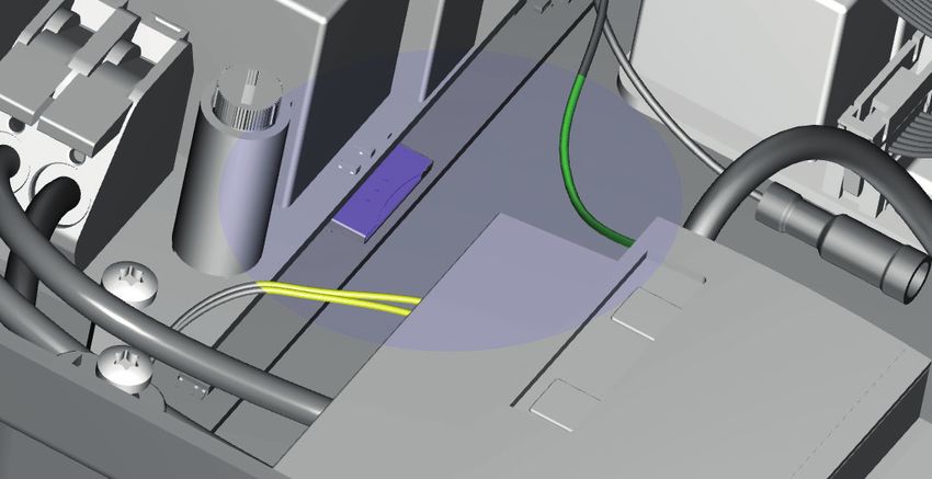
4.1 Electrical installation
WARNING
Read and follow all of the safety instructions in this manual!
ENGLISH
DANGER!
The electrical system must be disconnected from every
power source before performing any installation or
maintenance work!
1. Loosen the guide tube (M32) on the bottom, remove
the cable gland and disassemble it.
2. Place the ring over the power cable/charging cable.
3. Feed the power cable/charging cable into the charging Figure 7: Attaching individual charging cable wires..
station and slide the cable gland (and, if needed, the
filler washer) and the nut over the cable. 10. Attach the Control Pilot (CP) connector to the red
4. Remove the insulation with a wire stripper to reveal connection cable. This is right next to the connection
the wire cores far enough to fit them into the terminal for the power cables. See figure 8.
terminal block.
5. Attach the power cables to the connection clamps of
the filter block (see figure 8).
For installation of the model with socket, continue to
step 11.
6. Remove the cap ( 14 on page 2).
7. Repeat the previous steps 2 - 4 for the charging cable
included in the package.
8. Remove the transparent subframe by removing the
three Torx T20 screws. (See figure 6)
Figure 8: Connection clamps power cable and Control Pilot (CP)
connector for the charging cable (red) to Pro-line
11. Tighten the cable guide tube firmly so that the power
cable/charging cable does not have any slack.
12. Reattach the transparent subframe if you took it off
(tethered models only)
13. Press the front cover back onto the charging station.
14. Screw the front cover back onto the charging station
with the Torx T20 wrench. Use all six screws for this.
Figure 6: Detach subframe
9. Push the charging cable further in and connect the
wires to the outgoing clamps on the platform. See
figure 7 for the location on the 3-phase Pro-line
model. With the 1-phase model, only the connection
points for N and L1 are available.
22 Eve Single Pro-line DE manual | Version 1.0 | February 20204. COMMISSIONING THE CHARGING STATION
REMARK 4.3 Configuring the charging station with Service
The Service Installer application is available for download Installer Application
for Microsoft Windows on: www.alfen.com/en/downloads.
See the chapter 'EV charging points'. If you do not yet have 4.3.1 Preparation
an account to use the Service Installer application, you can Eve Single Pro-line DE charging stations are easily
ENGLISH
request one through http://support.alfen.com -> configured using the Service Installer Application. This
'Configuration Tool' -> 'Sign up for an account'. application allows you to access many settings, view the
factory settings and see all the completed transactions and
recognised charge passes.
4.1 Safety instructions before use
Follow the safety instructions below before commissioning The version number of the Service Installer Application is
your charging station: connected with that of the firmware to show you which
new functionalities are supported by your charging station.
1. Make sure the charging station is properly connected
to the power supply as described in this manual. Tip: Before installing the charging station, make sure you
2. Make sure the distribution of the power supply is have a user account and are using the newest version
separately protected by an appropriate breaker of the Service Installer Application. You can request an
(MCB or fuses) account at: http://support.alfen.com. Click on 'Sign up for an
3. Make sure the charging station is installed in account'. Note that new account creation may take several
accordance with this manual. working days.
4. Make sure the casing is always closed during
normal operation. Connect the charging station to your laptop with an
5. Make sure the charging cable is not twisted and that Ethernet cable (UTP).
the cable, plug and casing do not have any damage.
4.2 Commissioning Eve Single Pro-line DE models
Turn on the local power supply. The charging station will
run self diagnostics. The following steps will occur within
a few seconds:
1. The output is tested:
- Testing locks
- Testing internal relays: you will hear these click.
2. The display will illuminate briefly.
3. The display turns on and displays the message
'Charging station is powering up'.
4. The display will show the start screen, recognisable
by the logo on the screen.
5. The Eve Single Pro-line DE is now ready for use. If
the charging station is set to connect with the
management system, it will do so directly and
automatically.
6. If desired, the charging station can be configured
further. Use the Service Installer software package
to gain access.
7. Have you had the charging station configured for
Smart Charge functionality? If so, check the settings
with the Service Installer application to optimally
configure the charging station for the local situation.
More information is available in Appendix B.
Eve Single Pro-line DE manual | Version 1.0 | February 2020 234. COMMISSIONING THE CHARGING STATION
4.3.2 Using the Service Installer application
When you log in, you will see the charging station settings divided into different categories. In most cases, the charging
station has already been configured according to preferences with few adjustments necessary. If you ordered the smart
charge options (see Appendix B) , check the settings and adjust them where necessary to optimally configure the charging
station for its location.
ENGLISH
The Service Installer application is divided into the following categories:
General charging stations settings and Settings on the user interface/display
status information
Power settings to configure the charging Load balancing, all of the smart charging
station for the local grid options and settings in one location
Authorisations: managing charge passes and Activity log of the charging station
methods for user authorisation
Transaction information for historic and Live monitoring: Take a look at the status of
current transactions the charging station
Connectivity settings e.g management Warnings: shown in a single overview for quick
system connection settings (see paragraph analysis
4.3), mobile communication (GPRS) and local
network settings.
Functionalities shown in grey were not specified when ordering and so the charging station does not support them.
4.3.3 Changing language settings
Alfen's charging station interface supports ten different languages.
Changing the language can be done in two ways:
1. Via the Service Installer application; proceed from General Settings to 'Localisation'. Where, you can edit the
language settings.
2. Via a connected management system; Go to the language settings screen on the management platform. Every Alfen
charging station has the 'Language' setting item. The table below provides an overview of the languages supported.
Language Country Language Country Language Country Language Country Language Country
code code code code code
Dutch nl_NL German de_DE Spanish es_ES Italian it_IT Swedish sv_SE
English en_GB French fr_FR Portugese pt_PT Norwegian nn_NO Finnish fi_FI
4.4 Activate functionality with the Service Alfen charging stations offer the unique possibility to
Installer application be upgraded with new functionalities, even if these did
The charging station is connected to Alfen through the not yet exist when the station was purchased. Returning
Service Installer Application. When necessary, you can to factory settings or retrieving a new 'license' will be
retrieve the last known settings. This makes it possible to sufficient. If the option is then activated, you can use and
go back to factory settings or to retrieve new settings. install it as desired.
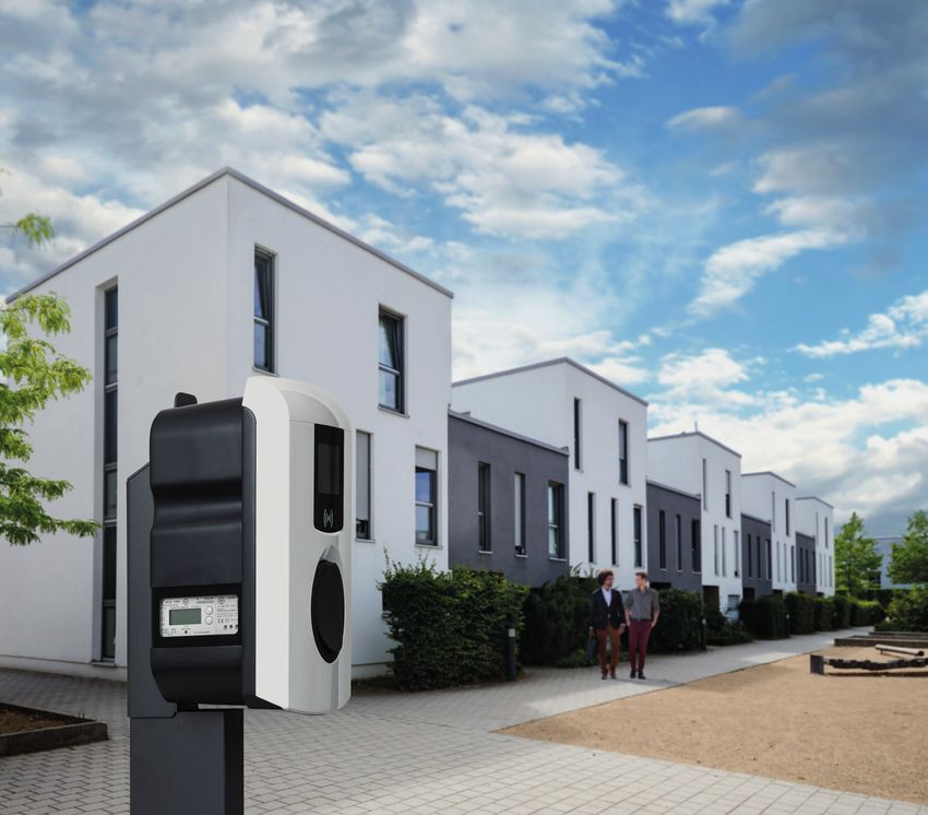
24 Eve Single Pro-line DE manual | Version 1.0 | February 20205. CONNECTIVITY
5.1 Management systems
Alfen charging stations are intelligent, and can
communicate with a range of online third party
management systems or our own, Alfen ICU EZ. All of
these provide the opportunity to track users’ energy
ENGLISH
consumption, control charging remotely and simplify
charging station maintenance via remote access.
Each charging station is already configured to directly 7
connect with the chosen management system at point
of manufacture, with internet connection established via Figure 9: location of SIM card holder
GPRS or a UTP (Ethernet) cable connection depending
on the model and/or customer preference. Where a GPRS
connection is available, and was specified, the charging WARNING
station is usually supplied with the SIM card installed and The SIM card holder needs to be handled with the utmost
will connect automatically once the product is powered on. care. To access the SIM card holder, disconnect the
If the SIM card holder (item. 7 on page 3) does not contain transparent subframe (3 x Torx T20 screw). To install a
a SIM card, it will either be included in the package or can card, access the SIM card holder from the left side. This will
be back-ordered. If in doubt, please contact the reseller or provide you with more space. Be careful not to crush any
provider. cables while replacing the subframe.
For more information on the Alfen management system ICU 5.2.2 UTP (Ethernet) connection
EZ, visit: www.alfen.com/en/ev-charge-points/services Which cable do you need?
A CAT5 UTP cable (max. 100 metres) is the minimum
5.2 Setting up a connection required to connect the charging station to the internet.
5.2.1 Wireless connection This cable is suitable for speeds up to 100Mbps.
To connect wireless, the charging station must be
equipped with a SIM card suitable for GPRS. The correct Installation
settings must also be chosen to connect with the desired 1. Connect the UTP cable to your router.
management system. 2. Make sure the charging station is turned off
(de-energised) at the local installation.
There are several (short cuts) in the Service Installer 3. Feed the UTP cable in through one of the grommets
Application to support this. These allow easy selection on the rear of the casing. Then, fix the connector
of the desired management system and related settings. onto the cable and connect to the Ethernet port on
Always check the signal strength after installation, using the upper left-hand corner on the charging station
the Service Installer Application. controller ( 5 on pages 2 and 3). Use the right RJ45
connector for a solid core or flex core cable.
REMARK A connector suitable for both types is also sufficient.
Whether and which management system a charging station
Be careful not to damage the core(s).
connects to is arranged by the company reselling the
4. Connect the charging station as described in paragraph
product. This inclusdes the services offered via this system,
3.4 and then turn on the power supply on the local
which are outside the scope of delivery of Alfen.
installation.
5. In order for your charging station to communicate with
Where Alfen ICU EZ online management system was ICU EZ via an UTP Ethernet connection, it may be
specified when ordering, the Eve Single Pro-line DE necessary to change your network settings if these
will already have a SIM card installed and will connect are additionally secured. The necessary information to
automatically when the product is powered on. If you chose obtain access through your network is:
another management system when ordering, you might - IP address ICU EZ: 93.191.128.6
need to install the SIM card yourself. Figure 9 shows the - Port: 9090
location of the SIM card holder. - FTP port: 21
- Inbound - outbound
Eve Single Pro-line DE manual | Version 1.0 | February 2020 255. CONNECTIVITY
It might be necessary to add a MAC address. You can find 5.4 Managing settings
this in the Network Settings tab in the Service Installer If your charging station is connected to a management
Application. system, it is possible to manage settings remotely even
without using the Service Installer Application. Alfen
charging stations offer many configuration
REMARK
ENGLISH
possibilities, for everything from basic settings to advanced
Make sure your network settings allow connection to the smart charge settings. These fall broadly into the following
Alfen servers through a secured FTP connection. This categories:
enables software updates and the exchange of diagnostics. • General information, such as the present charging
current and temperature
5.3 Register your ICU EZ account • General settings for the charging station like language,
If you want to enter into a contract for ICU EZ management intensity of the status indications and charging capacity
services with Alfen, visit: www.alfen.com/en/services/ • Switching between RFID and Plug & Charge
management-charging-stations to register. • Settings for transaction messages
• Smart charge settings
REMARK • Connectivity
You can only register as a user once you own an Alfen • Smart Charging Network
Charging Station configured for ICU EZ. In order to register, • Overview of activated options (see paragraph 2.7) and
you will need the information for your first charging station. possibility to change (license code)
We use this information to identify you. As soon as your
account has been set up, you will receive a confirmation Alfen innovates continuously. Settings are regularly
email to enable your account and set your password. Did added, extended, adjusted and removed. The latest version
you forget to register, but you have already ordered the of all settings can always be found at:
ICU EZ? No problem. If you ordered the charging station to www.alfen.com/en/downloads
be configured to ICU EZ, your charging station is already
registered and active in the management system. All 5.5 Register your charging station to your own
transactions and other actions from the past are saved and management system
visible to you. When using a non-Alfen management system, it is essen-
tial that you register the charging station model. The Eve
1. Complete the registration form on the Alfen website. Single Pro-line DE model will send a ChargePointModel in
2. In the 'remarks' field, enter the numbers located on the accordance with OCPP specifications when logging in. The
back of your charge passes. table in paragraph 2.6.1 indicates available options.
3. Click 'Send'.
4. Alfen will process your request and activate your
account. Your login details will be sent as soon as
possible.
5. With these login details, you will be able to log in to
the website www.alfen.com/en/more/login.
6. After logging in on ICU EZ, you will be able to access
your charging station and its status immediately.
26 Eve Single Pro-line DE manual | Version 1.0 | February 2020APPENDIX A: ERROR CODES AND PROBLEM-SOLVING
This appendix provides a description of, and advice related to, the error codes that can be generated by the Eve Single Pro-
line DE charging station. If you are not able to find a working solution, please contact the seller of the charging station, or
contact Alfen Support using the contact information displayed on the back of this manual.
Code Alarm message text Icon Possible causes Possible solutions
ENGLISH
001 Not able to charge. Generic Error. Contact the service department of your
Please call for support. charge point supplier.
Charge point error
101 One moment please. Your DC fault current (>6mA) One specific vehicle: Contact your car
charging session will detected by charging station. dealership.
resume shortly.
Multiple vehicles: Contact
the service
department of
your charge point
supplier.
102 Not able to charge. Internal error. Contact the service department of your
Please call for support. charge point supplier.
104 Not able to charge. Error internal voltage. Contact the service department of your
Please call for support. charge point supplier.
105 Check installation or call Internal error. Contact the service department of your
for support. charge point supplier.
106 Not able to charge. Power interrupted by internal Contact your installation engineer.
Please call for support. 30mA AC residual current
protection device.
Installation error
201 Error in installation. Protective earth not Contact your installation engineer.
Please check installation connected or unstable.
or call for support.
202 Input voltage too low, not Supply voltage below 210 Contact your installation engineer.
able to charge. Please call VAC.
your installer.
206 Temporary set to Charging station is set to Contact your charge point operator.
unavailable. Contact CPO inoperative by the Charge
or try again later. Point Operator.
211 Not able to lock cable. Unable to move lock motor Contact your installation engineer.
Please call for support. during start-up.
212 Error in installation. Missing phase in installation. Contact your installation engineer.
Please check installation
or call for support.
Vehicle error
301 One moment please your Generic error. • Check car and charging cable.
charging session will • Otherwise contact the service depart-
resume shortly. ment of your charge point supplier.
302 One moment please your Vehicle draws more current One specific vehicle: Contact your car
charging session will than allowed / did not dealership.
resume shortly. respond in time to reduce
charging speed. Multiple vehicles: Contact
the service
department of
your charge point
supplier.
Eve Single Pro-line DE manual | Version 1.0 | February 2020 27APPENDIX A: ERROR CODES AND PROBLEM-SOLVING
Code Alarm message text Icon Possible causes Possible solutions
Vehicle error
303 One moment please your Safety measure, charging is • Check car and charging cable.
charging session will started too often within 1 • Otherwise contact the service depart-
ENGLISH
resume shortly. minute. ment of your charge point supplier.
304 Charging not started Cable connected for more • Reconnect cable.
yet to continue please than 2 minutes without • Otherwise contact the service depart-
reconnect cable. starting a charging session. ment of your charge point supplier.
External factors error
401 Inside temperature high. Temperature inside the Unexpected Contact
Charging will resume charge point above 70 • Ambient temperature. the service
shortly. degrees Celsius. • No EV charging department
of your
charge point
supplier.
Expected: Contact your
• Ambient temperature. installation
• Installed in direct engineer.
sunlight.
• EV charging.
402 Inside temperature low. Temperature inside the Unexpected Contact
Charging will resume charge point below -40 • Ambient temperature. the service
shortly. degrees Celsius. department
of your
charge point
supplier.
Expected:
• Ambient temperature.
403 Charging not started Generic error. Contact the service department of your
yet to continue please charge point supplier.
reconnect cable.
404 Not able to lock cable. Unable to lock the charging • Check socket and charging cable plug.
Please reconnect cable. cable. • Otherwise contact the service depart-
ment of your charge point supplier.
405 Cable not supported. Check charging cable (PP One specific cable Cable broken.
Please try connecting value out of range according Issues with other
your cable again. to IEC norm values) charge points
All cables. No issues Contact
with other charge the service
points. department
of your charge
point supplier.
406 No communication with Check charging cable (CP One specific cable Cable broken.
vehicle value out of range according Issues with other
Please check your to IEC norm values) charge points.
charging cable
All cables. No issues Contact
with other charge the service
points. department
of your charge
point supplier.
28 Eve Single Pro-line DE manual | Version 1.0 | February 2020APPENDIX B: DEFAULT SELECTIONS FOR
OPTIONAL FACTORY SETTINGS
The Eve Single Pro-line DE charging station has the follow- The charging station and the smart meter communicate
ing Smart Charge options: via the P1 port. For this, the DSMR protocol is used (for
supported versions, see paragraph 2.6.5). Periodically,
1. Active load balancing: this offers the same functional- information on current usage is exchanged. When the
ity for managing charging speeds as the default load meter capacity is reached, the charging station will adjust
ENGLISH
balancing in double charging stations. Managing the the connected vehicle. This prevents the installation from
maximum charging current now, however, is a dynamic overloading, otherwise the cost of the grid connection will
process. The charging station communicates with the unnecessarily go up. This functionality effectively makes
smart meter in your installation or home and takes the for 'peak shaving', it controls the power supply during peak
current usage and maximal capacity of your grid connec- moments.
tion into account.
2. Smart Charging Network (SCN): When activated, Alfen If the P1 port of the smart meter is already occupied by an-
charging stations will recognise each other within a other device, you can use a splitter. For advice on splitters,
local network, a so-called charging plaza. In that case, please contact your dealer.
the local grid settings are shared between the charging
stations. Together, the charging stations decide how
much power each outlet - provided a vehicle is connect- NOTICE!
ed - will be allocated. To simplify the order process of Not all splitters can be used. 2-wire connectors cannot be
smart charge functionalities, a number of parameters used. In that case, your charging station might not be able
have been provided with default settings. This appendix to communicate with the smart meter. Alfen is not
provides the values of these settings. If your installation liable for continuous and correct operation of the
needs different settings from these defaults, use the connection to the P1 meter if this has multiple devices
Service Installer to configure the charging station for and/or splitters attached.
your specific situation.
To set up the active load balancing correctly, set the follow-
B.1. Active load balancing ing parameters:
Requirements for the installation: • Station-maxCurrent; This limits the maximum current on
• Alfen charging stations with activated Active Load the charging station group.
balancing functionality. • SmartMeter-maxCurrent; This is the capacity of your
• Communication cable with 4-wire RJ11/RJ12 grid connection. When in doubt, check this with your grid
connectors. operator.
• Smart meter supporting one of the following • Load balancing safe current (A): the value of the current
protocols: that remains available for the charging station (or charg-
- DSMR or eSMR over a P1 port. See paragraph 2.6.5. ing plaza) when the connection between the energy
for the supported versions of this protocol. meter and the charging station is lost.
- Modbus TCP/IP: the charging station will assume the
role of the Modbus Master in this configuration.
The smart meter is the Slave.
• The charging station is also able to communicate with a
customer’s Energy Management System (EMS).
-The communication protocol Modbus over TCP/IP is
used to transfer data from the EMS to the charging
station.
-In this case the charging station acts as a ‘slave’ and
the EMS as a ‘master’.
NOTICE!
Alfen recommends a maximum cable length of 20 metres,
combined with the P1 port. Always check if the communi-
cation with the smart meter is working properly. The quality
of the signals depend on several factors. Therefore, always
limit the cable length to prevent risks concerning the signal.
Alfen ICU B.V. is not liable for continuous and correct oper-
ation of the connection to the P1 meter and the quality of
the transferred signals.
Eve Single Pro-line DE manual | Version 1.0 | February 2020 29You can also read