General Aspects, Islanding Detection, and Energy Management in Microgrids: A Review - MDPI
←
→
Page content transcription
If your browser does not render page correctly, please read the page content below

sustainability

Review
General Aspects, Islanding Detection, and Energy Management
in Microgrids: A Review
Md Mainul Islam *, Mahmood Nagrial, Jamal Rizk and Ali Hellany

                                          School of Engineering, Design and Built Environment, Western Sydney University, Locked Bag 1797, Penrith,
                                          NSW 2751, Australia; m.nagrial@westernsydney.edu.au (M.N.); j.rizk@westernsydney.edu.au (J.R.);
                                          a.hellany@westernsydney.edu.au (A.H.)
                                          * Correspondence: mm.islam@westernsydney.edu.au

                                          Abstract: Distributed generators (DGs) have emerged as an advanced technology for satisfying
                                          growing energy demands and significantly mitigating the pollution caused by emissions. Microgrids
                                          (MGs) are attractive energy systems because they offer the reliable integration of DGs into the utility
                                          grid. An MG-based approach uses a self-sustained system that can operate in a grid-tied mode
                                          under normal conditions, as well as in an islanded mode when grid disturbance occurs. Islanding
                                          detection is essential; islanding may injure utility operators and disturb electricity generation and
                                          supply because of unsynchronized re-closure. In MGs, an energy management system (EMS) is
                                          essential for the optimal use of DGs in intelligent, sustainable, reliable, and integrated ways. In this
                                          comprehensive review, the classification of different operating modes of MGs, islanding detection
                                          techniques (IDTs), and EMSs are presented and discussed. This review shows that the existing IDTs
                                          and EMSs can be used when operating MGs. However, further development of IDTs and EMSs is
                                still required to achieve more reliable operation and cost-effective energy management of MGs in the
                                   future. This review also highlights various MG challenges and recommendations for the operation
Citation: Islam, M.M.; Nagrial, M.;       of MGs, which will enhance the cost, efficiency, and reliability of MG operation for next-generation
Rizk, J.; Hellany, A. General Aspects,    smart grid applications.
Islanding Detection, and Energy
Management in Microgrids: A               Keywords: demand response; energy management; islanding detection; microgrid
Review. Sustainability 2021, 13, 9301.
https://doi.org/10.3390/su13169301

Academic Editor: Thanikanti               1. Introduction
Sudhakar Babu
                                               To meet increasing energy demands, most governments and policymakers are search-
                                          ing for alternative energy sources because of growing environmental concerns, the continu-
Received: 20 June 2021
Accepted: 2 August 2021
                                          ous depletion of fossil fuels, and the high cost of traditional energy sources. Renewable
Published: 19 August 2021
                                          energy sources (RESs), such as wind and solar energy, do not generate emissions and cause
                                          low levels of pollution. Electricity generation from wind and solar energy meets more than
Publisher’s Note: MDPI stays neutral
                                          20% and 8%, respectively, of the total power demands in some countries, which means it
with regard to jurisdictional claims in
                                          can exceed the local power demand [1]. Figure 1 illustrates the market share of primary
published maps and institutional affil-   energy sources in global energy supply over a period of 200 years, which shows the efforts
iations.                                  made regarding systematically decarbonizing the global energy system [2]. Global energy
                                          systems are progressively becoming less carbon-intensive and involving more RESs. By
                                          2050, it is forecasted that the global energy system could become more efficient while
                                          connecting and distributing electricity to automobiles, factories, and buildings that rely on
Copyright: © 2021 by the authors.
                                          a modern, secure, and resilient electricity system. However, unlike traditional power gener-
Licensee MDPI, Basel, Switzerland.
                                          ation, RESs, especially wind and solar energy, provide a variable energy supply depending
This article is an open access article
                                          on the weather conditions. Thus, the uncertainty and inconsistency of RESs should be
distributed under the terms and           considered when estimating their power generation capacity. As a solution to this problem,
conditions of the Creative Commons        energy storage technologies such as batteries are typically used. Because of the current,
Attribution (CC BY) license (https://     massive deployment of RESs, the operation and economical schemes concerning energy
creativecommons.org/licenses/by/          storage and renewable technologies have gained more importance. RESs are typically used
4.0/).                                    to form microgrids (MGs) to meet consumer needs. This helps in attaining an effective

Sustainability 2021, 13, 9301. https://doi.org/10.3390/su13169301                                     https://www.mdpi.com/journal/sustainability
Sustainability 2021, 13, 9301                                                                                               2 of 45

                                shift from traditional grids into intelligent ones, a reliable and uninterrupted power supply,
                                and a two-way controlled power flow, in addition to improving power quality (PQ) and
                                protecting the environment [3].

                                Figure 1. Market shares of primary energy sources in the global energy supply since 1850.

                                     One main feature of MG technology is that it can operate in both grid-tied and islanded
                                modes. The proliferation of renewable source-based distributed generators (DGs) continues
                                with the increasing acceptance of MGs. The diverse deployment capability of MGs offers
                                several advantages, such as an increase in the integration of DGs into the grid, efficiency
                                improvement, cost reduction, and risk and emission reductions [4]. However, MGs still face
                                some challenges. For example, they require innovative management and control strategies
                                because traditional strategies cannot continuously respond to the dynamic behavior of
                                MGs [5]. Therefore, an appropriate control approach is required to assure smooth power
                                switching in MGs, particularly under islanding conditions. The control scheme must also
                                enhance the PQ of MGs and control the phase angles, frequency, and voltage variations
                                to maintain them within the desirable limits. The detection of islanding is essential for
                                avoiding hazards and PQ problems. Once the MG is detached from the utility grid (UG),
                                the controller can maintain a stable voltage and frequency to transfer sustainable energy to
                                consumers. An energy management system (EMS) is a key supervisory controller in the MG
                                system [6,7]. EMSs are applied to an MG scheme to maintain the energy balance between
                                sources and loads, to deliver better-quality, sustainable, reliable, and clean energy to
                                consumers [8]. In this review, an extensive overview of different aspects of MGs, including
                                their classification, operating modes, islanding detection (ID), and EMS of MGs with the
                                application of numerous optimization techniques, is presented and discussed.
                                     An MG-based literature database is introduced, considering three key objectives:
                                1.   To focus on the classification and modes of operation of MGs;
                                2.   To understand various methods of MG islanding-state detection;
                                3.   To include the maximum number of approaches for implementing MG EMS.
                                     The electronic databases Web of Science, SCOPUS, and Google Scholar were searched
                                by the authors for MG-related peer-reviewed publications, to create a dedicated database.
                                The search was implemented utilizing a combination of keywords. The references were
                                retrieved based on whether the keywords reflected our research objectives; the final re-
                                search database comprised 173 references from among 808 research articles (Figure 2) over
                                a 20-year timespan (2002–2021), based on the relevance of the research objectives. Among
                                these 173 references, 88% were from peer-reviewed journal articles, 8% were conference
                                proceedings, and 4% were books and websites. Moreover, journal details, such as the publi-
                                cation year, journal impact, and reliability of the reported results/data, were considered
                                while choosing the research papers.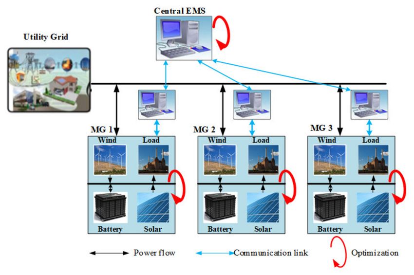
Sustainability 2021, 13,
Sustainability 2021, 13, 9301
                         x FOR PEER REVIEW                                                                                  33 of
                                                                                                                               of 45
                                                                                                                                  49

                                              Archives of previous               Supplementary
                                              studies via electronic            records via other
                                             web searching (N = 785)            sources (N = 18)

                                                             Archives after removing
                                                              duplication (N = 808)

                                                                Archives screened         Archives omitted
                                                                   (N = 415)                 (N = 393)

                                                                Articles evaluated
                                                                                          Articles omitted
                                                                  for eligibility
                                                                                             (N = 160)
                                                                    (N = 255)

                                                         Studies incorporated (N = 173)

                                                                                MG energy               Issues and
                                    Introduction    General aspects of
                                                                               management           recommendations
                                       (N = 8)       MG (N = 15)
                                                                                (N = 77)                 (N = 7)

                                                                    MG islanding
                                                                 detection (N = 66)

                                  Figure 2. Flow diagram of the review process.

                                  2. General
                                  2. General Aspects
                                              Aspects ofof MG
                                                           MG
                                  2.1. Microgrid Structure
                                  2.1. Microgrid Structure
                                       MGs are coordinated schemes that employ distributed energy resources (DERs) using
                                       MGs are coordinated schemes that employ distributed energy resources (DERs)
                                  a grid that can be linked or detached from the UG at the point of common coupling (PCC)
                                  using a grid that can be linked or detached from the UG at the point of common coupling
                                  (Figure 3). The PCC is the point where the power generation and loads are joined together.
                                  (PCC) (Figure 3). The PCC is the point where the power generation and loads are joined
                                  The following sections explore the components that establish an MG.
                                  together. The following sections explore the components that establish an MG.

                                  2.1.1. Distributed Generators (DGs)
                                        An MG is a wise choice for incorporating various types of DGs because they can
                                  utilize several sources in different locations. DGs such as wind turbines, photovoltaics
                                  (PVs), biomass and fossil fuel‐based generators and hydro‐turbines act as small‐scale
                                  power generators that can supply power to end‐users. They significantly reduce
                                  emissions [9]. DGs can efficiently produce and deliver energy, while offering significant
                                  environmental benefits. DGs include a controller to regulate frequency/voltage and
                                  active/reactive power to assure a successful and smooth connection with MGs [10].

                                  2.1.2. Storage Systems
                                        Energy storage systems (ESSs) are important components of MGs because they serve
                                  as standby power generators for RESs. ESSs store energy from local DGs when excessive
                                  energy is generated, or from the UG when the market price is low. They return energy to
                                  the grid during peak demand periods to reduce interruptions and maintain system
                                  stability. An ESS can significantly reduce the fluctuating effects of RESs, providing a cost‐
                                  effective MG operation and better system efficiency. Moreover, it can improve other
                                  system characteristics, such as stability, PQ, power imbalance, reliability, and remote MG
                                  operation.
                                  Figure 3. TheFurthermore,     ESSs can
                                                 layout of a microgrid     enhance transient and dynamic stabilities, voltage
                                                                       (MG).
                                  unbalance (VU), and frequency control to develop a dynamic power system. Several
                                  2.1.1. Distributed
                                  studies              Generators
                                            have presented          (DGs) discussions of ESS operations in power systems
                                                                extensive
                                  [11,12,13].
                                        An MG is a wise choice for incorporating various types of DGs because they can
                                  utilize several sources in different locations. DGs such as wind turbines, photovoltaics
                                  2.1.3. Loads
                                  (PVs),  biomass and fossil fuel-based generators and hydro-turbines act as small-scale power
                                  generators
                                        MGs can that can supply
                                                   deliver  powerpower    to end-users.
                                                                   to various           They such
                                                                              types of loads, significantly reduce emissions
                                                                                                   as for residential          [9].
                                                                                                                      or industrial
                                  DGs   can  efficiently produce   and  deliver energy, while offering significant environmental
                                  use, which are typically classified as critical and non‐critical loads to control and attain
Sustainability 2021, 13, 9301                                                                                             4 of 45

                                benefits. DGs include a controller to regulate frequency/voltage and active/reactive power
                                to assure a successful and smooth connection with MGs [10].

                                2.1.2. Storage Systems
                                     Energy storage systems (ESSs) are important components of MGs because they serve
                                as standby power generators for RESs. ESSs store energy from local DGs when excessive
                                energy is generated, or from the UG when the market price is low. They return energy
                                to the grid during peak demand periods to reduce interruptions and maintain system
                                stability. An ESS can significantly reduce the fluctuating effects of RESs, providing a cost-
                                effective MG operation and better system efficiency. Moreover, it can improve other system
                                characteristics, such as stability, PQ, power imbalance, reliability, and remote MG operation.
                                Furthermore, ESSs can enhance transient and dynamic stabilities, voltage unbalance (VU),
                                and frequency control to develop a dynamic power system. Several studies have presented
                                extensive discussions of ESS operations in power systems [11–13].

                                2.1.3. Loads
                                     MGs can deliver power to various types of loads, such as for residential or industrial
                                use, which are typically classified as critical and non-critical loads to control and attain the
                                expected operation of MGs [14]. This strategy prioritizes ensuring service to critical loads
                                and enhances the reliability and PQ of particular loads. Critical loads are disconnected
                                during grid faults using protective systems, and are then continuously operated using local
                                generation (users’ own generation facility) [14].

                                2.2. Mode of Operation
                                    MGs can operate in two modes, islanded and grid-tied modes [15]. In the following
                                subsection, these MG operation approaches are discussed in detail.

                                2.2.1. Islanded Mode
                                      MGs are typically linked to the UG through a PCC and are mostly tied to an electric
                                power network at medium (or low) voltage levels. In the islanded mode, the MG is
                                disconnected from the UG but can provide a consistent power supply to users, based
                                on DG bids. ESS-integrated MGs increase the effectiveness and reliability of the power
                                network, which in turn reduces the power fluctuations caused by RESs. In emergency
                                cases, if the MG is disconnected from the UG owing to network faults, the MG may operate
                                separately (in the islanded mode) with the support of DGs and the integration of battery
                                ESSs (BESSs) to maintain power network reliability and stability [16]. The primary objective
                                is to regulate the frequency and voltage of the network. Harmonization during the rejoining
                                of the MG with the network is recovered using frequency discrepancies between the UG
                                and MG in the islanded mode [9,17]. Figure 4 shows an MG system operating in the
                                islanded mode, using a switch for changeover actions.

                                2.2.2. Grid-Tied Mode
                                     In the grid-tied mode, MGs can deliver (or consume) energy to (or from) the UG, de-
                                pending on the power network requirement. Adopting BESSs along with MGs significantly
                                improves the system operation because they improve the reliability of the system [18].
                                BESSs can maintain frequency and voltage variations to keep them within tolerable ranges,
                                to ensure the reliability of MGs. Usually, BESSs are employed along with RESs to facilitate
                                standby generation, supply power to reduce the peak load demand during grid outages,
                                and control voltage and frequency to stabilize the grid. BESSs are also used in the demand
                                response (DR) approach in the grid-tied mode, to control the voltage and frequency of
                                the power system. Several studies, exploring BESS sizing and best scheduling, the EMS
                                approach, and the control of MGs in grid-tied schemes have been conducted to realize
                                economic electricity generation [9,18,19]. Grid-tied MGs include a PCC and an intelligent
                                bi-directional switch (Figure 5). The bi-directional switch manages the two-way connection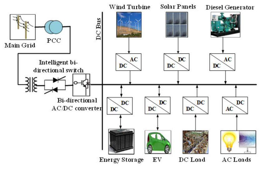
Sustainability 2021, 13, 9301                                                                                       5 of 45

                                of the MG to the main UG. The MG can take energy from the UG when it is needed, as well
                                as transferring surplus power to the UG.

                                Figure 4. Islanded mode of MG operation.

                                Figure 5. Grid-tied mode of MG operation.

                                2.3. Classification of MGs
                                    According to the operating method specified by the Consortium for Electric Reliability
                                Technology Solutions [15], MGs are classified into three groups: alternating current MG
                                (ACMG), direct current MG (DCMG), and hybrid AC–DC MG (Figure 6).

                                Figure 6. Classification of MGs.

                                2.3.1. Alternating Current MG (ACMG)
                                     An ACMG is linked to the UG via a PCC, in which a switch controls the MG operating
                                modes. A power electronic device is required for those DGs that produce a DC voltage,
                                including ESSs, to convert it into an AC voltage that can be connected to an AC-bus sys-
                                tem. Figure 7 represents an ACMG system connected to the UG via a PCC. An ACMG is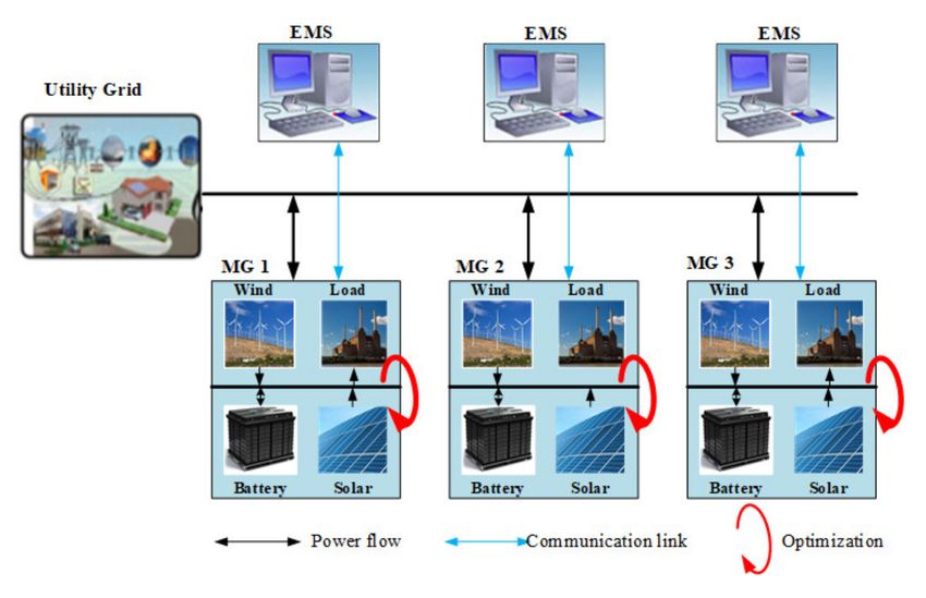
Sustainability 2021, 13, 9301                                                                                         6 of 45

                                simple to install and connect to the traditional UG when implementing a reconfigurable
                                system. The generators, storage devices, and user loads need to be compatible with the UG.
                                The voltage transformation and regulation are easy because of the electrical transformers.
                                Moreover, circuit protection and security schemes are mature for AC systems [14]. The
                                main shortcoming of the ACMG technique is that it requires vast and complicated power
                                electronic devices to integrate DGs with the UG, introducing a harmonic effect in the power
                                network [20]. In addition, parameters such as voltage magnitude, frequency, and phase an-
                                gle must be coordinated and harmonized with the existing UG. These requirements restrict
                                the use of ACMGs with UGs. An ACMG usually requires more additional transformation
                                stages than a DCMG [20].

                                Figure 7. ACMG-based power system.

                                2.3.2. Direct Current MG (DCMG)
                                     The DCMG scheme can be efficiently integrated with DGs, as it mainly generates a
                                DC voltage. ESSs and RESs both operate with a DC voltage. DCMG systems are typically
                                attached to the UG through a PCC. In this technique, ESSs, PVs, electric vehicles (EVs),
                                and DC loads are linked to the DC bus via DC–DC converters. AC loads, along with
                                wind turbines and diesel generators, are attached to a DC bus through AC–DC converters.
                                Figure 8 illustrates the structure of a DCMG system. The architecture of the DCMG system
                                is much simpler than that of an ACMG system, as it does not require grid harmonization
                                of DGs, harmonics, and reactive power flow, which improves the system efficiency [21].
                                However, the use of power electronic converters creates reliability problems and contributes
                                to the ineffective power flow control from/to the distribution UG [14].

                                Figure 8. DCMG-based power system.
Sustainability 2021, 13, 9301                                                                                                    7 of 45

                                    2.3.3. Hybrid AC–DC MG
                                          This approach is a combination of ACMG and DCMG. In this architecture, the ACMG
                                    is directly linked to the PCC. However, the DCMG uses a two-way AC–DC converter to
                                    connect with the AC-bus system [22]. A control unit is required in each converter to ensure
                                    the reliability and effectiveness of the network. The control unit is situated between the UG
                                    and network buses (Figure 9). A bidirectional converter is employed to control and regulate
                                    the DC bus voltage and power flow between the AC and DC MG. The main advantage
                                    of hybrid MGs is that the DG units can be easily connected to the DC- or AC-bus because
                                    DGs do not require synchronization. Thus, the control is simple and reduces energy losses.
                                    However, the control schemes in MG have some problems, which are discussed in [23].
                                    Table 1 gives a comparison between various MG operation schemes.

                                    Figure 9. Hybrid MG-based power system.

                                             Table 1. Comparison between MG operations.

       Type                     Conversion                     Merits                          Demerits                     Refs
                                                                                     Requires vast and complicated
                          DC loads require an                                          power electronic devices to
                                                     Easy reconfiguration; easy
                           AC–DC converter;                                             integrate DGs into the UG;
      ACMG                                            voltage transformation                                              [14,15,20]
                       AC loads can easily connect                                 difficult to synchronize the voltage
                                                           and regulation
                               to the bus                                          magnitude, frequency, and phase
                                                                                        angle with the existing UG
                                                          Few converters
                                                                                   Reconfiguration with the existing
                                                           are necessary;
                                                                                            UG is complicated;
                      Requires a DC–DC converter        DC loads can easily
      DCMG                                                                         difficult to produce an AC voltage;     [14,21]
                         and DC–AC inverter             connect to the bus;
                                                                                           difficult to maintain a
                                                        no synchronization
                                                                                        standardized voltage level
                                                              required
                      A transformer is used on the
                                                     Both AC and DC loads can
                         AC side, and a DC–DC                                       Difficult to manage and control;
   Hybrid MG                                          easily connect to the bus;                                           [22,23]
                        converter is used on the                                          complex architecture
                                                           less energy loss
                                DC side

                                    3. Islanding Detection (ID)
                                         MGs can operate in islanded or grid-tied mode, based on various approaches. An effi-
                                    cient islanding detection technique (IDT) is essential for achieving optimal MG operation.
                                    System reliability is a key priority in the islanding approach, whereas the main goal of the
                                    grid-tied approach is to achieve the best economic operation of MGs. Thus, identifying
                                    the operation state in real time is indispensable for maximizing the performance of MGs.
                                    Islanding may be subdivided into controllable and uncontrollable islanding [24]. Control-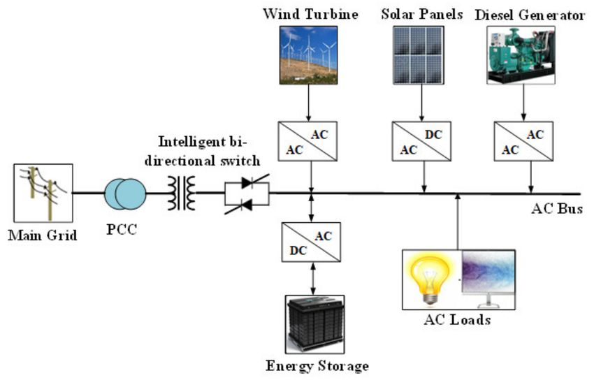
Sustainability 2021, 13, 9301                                                                                                       8 of 45

                                    lable islanding involves MGs consistently delivering power to fulfill the load while they
                                    are disconnected from the UG. Unplanned islanding is an undesirable situation caused
                                    by problems such as equipment failure, line-tripping, and human errors, with MGs being
                                    detached from the UG. This may occur infrequently and affect the safety of MG.

                                    3.1. ID Standards and Test Indices
                                          An MG should detect the failure of the grid connection and isolate itself from the
                                    power supply network within 2 s of the occurrence of unplanned islanding [25]. A reliable
                                    and efficient IDT is required for detection. Many ID standards have been prepared as
                                    instructions for researchers to develop and enhance IDTs. These standards incorporate
                                    IEEE Std.1547-2003, IEEE Std. 929-2000, UL 1741, IEC 62116, the Canadian C22.2, UK
                                    G83/2/3, Korean, German VDE0126-1-1, Japanese and AS4777.3-2005 [25–28]. Table 2
                                    lists the standards for ID, giving its required detection time, quality factor, frequency, and
                                    voltage operating range. Rapid detection is a prerequisite for MGs to have sufficient time to
                                    operate the islanding approach, ensuring security and reliability. Islanding disconnection
                                    time is also imperative. The German VDE0126-1-1 standard has the strictest disconnection
                                    time limit, below 0.2 s [29]. Besides detection time, the quality factor (Qf ) is also important.
                                    According to the IEEE929-2000 standard, Qf can be represented as shown in Equation
                                    (1). The selected Qf of 2.5 corresponds to a power factor (PF) of 0.37. As PF increases, Qf
                                    decreases. Therefore, the test requires that Qf ≤ 2.5 equates to lines with uncorrected PFs
                                    from 0.37 to unity, and appears to cover all reasonable distribution line configurations [29].
                                    With the Qf at zero, where either capacitive or inductive loads are zero, the Japanese
                                    standard recommends introducing a rotating machinery load when the MG is investigated
                                    for anti-islanding. The machinery load is supposed to behave in such a way as to increase
                                    the Qf . In addition to the Qf , the voltage/frequency operation range also influences the
                                    ID capability. The Australian Standard AS4777.3-2005 and Japanese Standard require that
                                    frequency and voltage ranges are set by the manufacturer.

                                                                         Q f = tan(arccosine[ PF ])                                    (1)

                                                          Table 2. ID Standards.

          Standard                Detection Time           Quality Factor            Frequency (Hz)                Voltage (p.u.)
        IEEE 1547                       t
Sustainability 2021, 13, 9301                                                                                                9 of 45

                                •    Power Mismatch Space
                                     The frequency and voltage variations at the PCC are related to the power discrepancy
                                between generation and load demand when the MG works in a scheduled mode. The
                                power mismatches, ∆P and ∆Q, will be zero if the DG power generation and load demand
                                are equal [31]. ∆P and ∆Q can be obtained using Equations (2) and (3), respectively. The
                                quality factor (Qf) is described as the strength of resonance of the islanding test load,
                                as shown in Equation (4). NDR is obtained using these equations (Figure 10) [32]. For
                                ∆P and ∆Q in the shaded region, islanding is not detected. Another effective method
                                was introduced in [33] to determine the NDRs for a typical frequency and voltage for
                                synchronous-based DG. The approach is feasible for assessing NDR using a few analytical
                                statements, without the need for time-consuming simulations.
                                                                          2                            2
                                                                                      ∆P

                                                                  V                               V
                                                                               −1 ≤      ≤                   −1                 (2)
                                                                 Vmax                  P         Vmin
                                                                             2 !                                    2 !
                                                                                    ∆Q

                                                                      f                                       f
                                                      Qf 1 −                      ≤     ≤ Qf 1 −                                (3)
                                                                     f min           P                       f max
                                                                                        r
                                                                                          C
                                                                                 Qf = R                                         (4)
                                                                                          L
                                where Vmax and Vmin are the maximum and minimum voltages permissible in MG; fmax and
                                fmin are the maximum and minimum frequencies; V and P are the rated voltage and active
                                power; ∆P and ∆Q are the active and reactive power mismatch, respectively; Qf is the
                                quality factor; R, L, and C are the load resistance, inductance, and capacitance, respectively.

                                Figure 10. Schematic of NDR.

                                •    Load Parameter Space
                                     NDR in the load parameter space can be represented as:

                                                             F1 (c f , G, Q f ) < ∆Cres < F2 (c f , G, Q f )                    (5)

                                where cf , G, and Qf are the chopping fraction, acceleration gain, and quality factor, respectively.
                                     In [31], the author used the L × Cres axis (inductance × resonate capacitance) to define
                                NDR in the load parameter space. In this technique, the load resistance is determined by
                                assuming a power match between the DG and load demand. In [34], an alternative method
                                considering Q × fr was employed to define NDR, where fr is the resonance frequency. The
                                key advantage of this technique, compared with the previous technique, is that it does not
                                require the use of various curves to analyze NDR with numerous resistive loads.

                                3.1.2. Detection Time
                                   Detection time is the period between the MG’s disconnection from the UG to the
                                moment of islanding detection by IDTs, and is given as:

                                                                               ∆T = TIDT − Ttrp                                 (6)
Sustainability 2021, 13, 9301                                                                                         10 of 45

                                where ∆T is the run-on time, TIDT is the time of islanding, and Ttrp is the time at which the
                                MG disconnects from the UG.

                                3.1.3. Error Detection (ED) Ratio
                                     The ED refers to a situation in which the IDT identifies incorrect islanding, although
                                the MG is connected to the UG. The incorrect ID may happen because of load switching
                                or various disturbances, which leads to the measurement tools surpassing their limit [35].
                                The ED ratio can be estimated as follows:
                                                                                 Ned
                                                                       Er =                                               (7)
                                                                              Ned + Ncd

                                where Er is the ED ratio, and Ned and Ncd are the total numbers of ED and correct detection,
                                respectively.

                                3.1.4. Power Quality (PQ)
                                     Techniques that consider disturbance injection can considerably diminish NDR when
                                identifying islanding. Nonetheless, it is necessary to introduce interference to deform
                                the power output profile and degrade PQ. This is an important test parameter when
                                selecting IDTs.

                                3.1.5. Effect on MG
                                    Injecting disturbances in the system does not have any considerable impact when the
                                DGs are attached to the UG. However, it considerably reduces PQ if the MG is detached
                                from the UG. Therefore, IDTs with less impact on the MG are preferred.

                                3.1.6. Implementation Cost
                                      Several IDTs incorporate improved and sophisticated hardware for improving op-
                                eration. However, higher performance at a huge investment cost reduces its practical
                                utilization. Therefore, an optimal balance should be maintained between performance and
                                the investment cost in real-time applications.

                                3.2. Islanding Detection Techniques (IDTs)
                                     IDTs are generally categorized as remote (central) and local (Figure 11). Local IDTs
                                measure the parameters on the MG side. They are further subdivided into passive, active,
                                and hybrid techniques [36]. Passive techniques directly monitor parameters such as current,
                                voltage, phase, and frequency for ID. Active techniques purposefully introduce a noisy
                                disturbance to check whether it affects the frequency, voltage, and other parameters of
                                the system.

                                3.2.1. Local Techniques
                                     The local techniques are classified into three groups. These are described in the
                                following subsections.
                                •    Passive Techniques
                                     These were the first techniques used for ID. The passive IDTs directly monitor pa-
                                rameters such as current, voltage, total harmonic distortion (THD), and frequency at the
                                PCC to the UG. A threshold limit is defined for the parameters, and the outstripping of
                                this predefined limit denotes islanding. The parameters significantly differ if the MGs are
                                isolated. The protective relays sense the deviations and send a signal to trip the breaker
                                switch. Figure 12 shows the basic block diagram of a passive IDT. Studies have introduced
                                several passive IDTs, some of which are discussed below.
                                1.   Under/overvoltage (UOV) and under/over frequency (UOF): UOV/UOF is the oldest
                                     passive technique. It operates based on the setting of the allowable range of voltage
                                     and frequency. This technique is employed in all grid-tied inverters to measure
Sustainability 2021, 13, 9301 11 of 45
various abnormal conditions. Inverters stop the supply of power (both active and
reactive power) if the frequency and voltage exceed the predefined limits at the PCC.
In the MG, the power discrepancy between the generation and load demands at the
PCC can be represented as follows:
∆P = Pload − PDG (8)
∆Q = Qload − Q DG (9)
where ∆P and ∆Q are the active and reactive power mismatch; Pload and Qload are the
active and reactive load; PDG and QDG are the active and reactive DG power.
In the grid-tied mode, the UG adds ∆P and ∆Q to balance the active and reactive
power. However, if islanding occurs, its frequency and voltage will drift until the
active and reactive powers are balanced; thus, this technique detects islanding by
measuring frequency and voltage variations.
Although this technique has no impact on PQ, its primary weaknesses are its extensive
NDR and unpredictable detection time, which may exceed 2 s [37]. One method was
proposed to minimize NDR by implementing an interface control in parallel to UOV
and UOF [38]. Another method proposed decreasing the NDR by controlling the P–V
and P–Q characteristics of constant-current-controlled inverters [36].
2. Harmonics measurement: this technique monitors the change in THD and primary
harmonics (3rd, 5th, and 7th) at the PCC to identify MG isolation [39]. Under normal
conditions, when the MG is connected to the UG, insignificant harmonics are intro-
duced by loads because the grid impedance is small. When the MG operates in the
islanding state, the inverters develop current harmonics, which are transferred to the
load, and the transformer’s hysteresis effect further exacerbates harmonic distortions
at the PCC. Thus, MG islanding can be easily identified [40].
The implementation of this technique is easy even when multiple DGs are connected
to the same PCC. Conversely, high Q-factor detection using this technique is difficult,
and detection limit selection is challenging because UG disturbance can easily induce
false detection [36].
3. Phase Jump Detection (PJD): this technique is based on measuring the phase dis-
crepancy between the output current and terminal voltage of the inverter, which
typically occurs as a sudden “jump.” In normal MG operation, the inverter’s current
and voltage will be harmonized at the PCC by modifying the phase-locked loop (PLL)
required by the inverters. If isolation occurs, the local load and inverter are separated
from the UG. The PJD system checks variations in the phase angle to identify island-
ing [31]. This approach is simple to implement, does not distort the inverter PQ, and
can be used in multi-inverter systems [41].
The main limitation of this technique is in the setting of detection limits because of
the load-switching effects. It is challenging to detect islanding using this technique
if the loads do not generate a large enough phase error. Thus, PJD is useful only for
MGs that evince nearly constant load switching and a large phase angle.
4. Rate of Change in Frequency (RCF): The frequency will change if the MG disconnects
from the UG. When the frequency surpasses a set limit, the inverters shut down,
and islanding is identified. RCF is evaluated over a few cycles [42]. RCF is more
responsive, and its detection time (24 ms) is less than that of UOV/UOF [43]. Any
distortion generated by load variations could lead to frequency deviations in ID.
Nonetheless, when severe frequency deviations occur, the detection time can be in
fewer than five revolutions [44]. The main shortcoming of RCF is that it is very
responsive to load fluctuation and switching (even a small disturbance can change
the frequency), which may affect ID. Moreover, the selection of the detection limit
is challenging. This technique is unable to discriminate between islanding and load
variations as the cause of frequency change [45]. Thus, RCF is not suitable for loads
with high variations.Sustainability 2021, 13, 9301 12 of 45
5. Rate of Change in Power (RCP): This technique monitors DG power output changes
because the disconnection from the grid causes load changes. When the MG is
islanded, the RCP output will be higher than that of the MG in the grid-tied mode,
even when the load change rate is equal in both cases. Thus, the power changes are
monitored for a few test cycles. The MG will be isolated from the UG if the combined
changes in the test cycles surpass the set detection limit. The rate of change in the
reactive power approach was proposed in [46] to detect the islanding of synchronous
generator-based DGs.
The usual detection time of RCP is approximately 24–26 ms [43]. In comparison
with UOF, the detection time is not affected by such small power discrepancies. This
technique can also immediately identify uncoordinated reclosing of the UG supply to
the MG to ensure the reliable functioning of the electric power network. However,
this technique has an NDR, even under power balance conditions.
6. Voltage Unbalance (VU): When the MG disconnects from the UG, the VU of DG
changes because of the change in the network topology. If the unbalance in the
three-phase DG output voltage surpasses the allowable limit, this is considered
islanding [47]. The VU deviation is monitored and compared under normal and
steady-state loading conditions, and any unexpected VU is identified as MG islanding.
The single-cycle average of VU and VU deviation was investigated every 1/4 cycles
(4.17 ms) in [48]. Recently, single-cycle control-based inverters to detect islanding
were proposed in [49], where simulation results showed that this technique could
work effectively with less NDR.
Passive detection techniques are cost-effective, easy to implement, and have short
detection times. Thus, these techniques can handle most of the instabilities that occur
in the UG. Nevertheless, the main shortcoming of passive IDTs is the large NDR, which
hampers the identification of the correct MG operating state. In addition, the load
affects islanding detection in these techniques. These shortcomings could be resolved
using active IDTs, which are discussed in the following section. Table 3 gives a
comparison between various passive IDTs, highlighting their benefits and limitations.
Table 3. Comparison of passive islanding techniques.
Detection Error Implementation
IDT NDR Improvement Ref
Speed Detection Rate and Speed
Additional
parameter is
UOV/ Easy but reaction time
Large 4 ms to 2 s - implemented [36–38]
UOF is variable
with the
UOV/UOF
Large with a Easy but challenging to
THD 45 ms High [36,40]
high Q factor define a threshold
Complicated
implementation, Controlled
PJD - 10 to 20 ms High [41]
challenging to define a using a PLL
threshold
Easy but selection of
RCF small 24 ms High - [43,45]
threshold is difficult
Smaller than More complicated than
RCP 24 to 26 ms - - [43]
UOV/UOF UOV/UOF
Combining VU
Easy for a and THD to
VU - 53 ms Low [47,48]
three-phase system enhance the
performanceSustainability 2021, 13, 9301 13 of 45
Figure 11. Classification of IDTs.
Figure 12. Basic block diagram of a passive IDT.
• Active Techniques
Active IDTs are implemented by injecting a minor disturbance, as shown in Figure 13, into
the UG to determine whether the MG is in the islanding state (Figure 13). The disturbance is
injected at specific intervals. Numerous active IDTs have been introduced in the literature;
some of them are discussed in the following subsections.
1. Impedance Measurement (IM): this technique involves varying the current amplitude
of the inverter. When the MG is separated from the UG, the voltage magnitude
changes because of the change in the current’s magnitude, which causes an impedance
variation that can be employed for ID [40]. However, in an active direct technique,
a shunt inductor is temporarily attached to a supply voltage. The supply voltage
reduction and short-circuit current approaches are utilized to determine the power
system source impedance [36].Sustainability 2021, 13, 9301 14 of 45
The IM-based ID time is approximately 0.77–0.95 s [29], and its NDR is very small
for individual DG systems, which is its main advantage. However, this technique
has many limitations, including its low detection performance for multi-inverter
arrangements, except when all inverters are working simultaneously. Moreover,
it is difficult to define the impedance base limit because IM requires a precise UG
impedance value. Thus, the practical implementation of this technique represents a
challenge.
2. Sliding Mode Frequency Shift (SMFS): this technique employs positive feedback to
vary the phase at the PCC, followed by using the temporary frequency to identify
islanding. The phage angle of the inverters can be defined as follows:
!
π f m −1 − f y
θ = θ x sin (10)
2 fx − fy
where θx is the maximum phase angle at the frequency fx, and fy and fm − 1 are the
rated and previous cycle frequency, respectively.
When the MG is operating under normal conditions, the phase angle between the
PCC voltage and inverter current is maintained at close to zero. The phase angle of
the frequency and load may change when the MG is detached from the UG. Thus,
islanding can be detected if the frequency deviation surpasses the set limit [50]. The
detection time of SMFS is approximately 0.4 s [34]. The main benefits of SMFS are
that its implementation is easy, and it has a smaller NDR than other active techniques.
However, this technique reduces the grid PQ and transient stability. These problems
are common for all techniques that use positive feedback. This could be solved by
including an extra phase shift, called the enhanced-SMFS [50].
3. Active Frequency Drift (AFD): similar to SMFS, this technique employs positive
feedback to change the frequency of the inverter current. In a grid-tied mode, the
PCC voltage and frequency will not change, owing to the steadiness of the UG. When
grid separation occurs, the voltage crosses zero earlier than expected, thus creating
a phase discrepancy between the inverter’s current and voltage. This induces the
inverter to drift the frequency of the current to cancel the phase discrepancy. The drift
frequency outstrips the set limit, and islanding can be identified [47].
The advantages of AFD are that its implementation is simple, and it has a small NDR.
Notably, no NDR is present in resistive loads within a sensing period of 2 s [29].
However, this technique is unable to detect islanding for multiple inverters because of
various deviations in the frequency bias of the inverters [51]. The PQ of the inverter
output deteriorates more rapidly with the increase in the distortions in the injected
current. Load parameters have a significant effect on this technique. The islanding
sensing time and NDR increase with higher Q values if the load is not resistive. Thus,
AFD is only suitable for an ID of MGs comprising resistive loads and a single inverter.
The Fourier series coefficients and RMS value of the current waveform are used to
improve traditional AFD. This approach can decrease THD by approximately 30%
of the current waveform. Hence, the technique can rapidly identify islanding with
a reduced NDR. The performance of the traditional approach can be significantly
enhanced by using AFD with positive feedback (AFDPF) [52].
4. Sandia Frequency Shift (SFS): this technique, typically called AFDPF, is a modification
of AFD that uses positive feedback for ID. At PCC, this technique tries to alter
the voltage frequency when attached to the UG, but the UG prohibits this. When
detachment from the UG occurs, the chopping coefficient increases with the frequency
increase at PCC. This results in an increase in the inverter frequency. This frequency
shift enables efficient ID. The ID time here is approximately 0.5 s.
The implementation of this approach is simple, and its NDR is small compared with
those of other active IDTs. SFS is used in conjunction with the Sandia voltage shift
(SVS)-related islanding technique, which is a very efficient approach [53]. Nonethe-Sustainability 2021, 13, 9301 15 of 45
less, SFS significantly affects the PQ and the system stability, which may lead to
adverse behavior in the system response. Furthermore, positive feedback introduces
harmonics and noise [54].
5. Frequency Jump (FJ): this is another modified form of AFD, based on varying the
voltage frequency to identify islanding. When the MG is detached from the UG,
islanding could be determined by an alteration in the voltage frequency [29,31]. FJ is
efficient in discovering MG isolation with a single inverter. However, as is similar to
AFD, the identification efficiency decreases when multiple inverters are connected
in parallel.
6. Sandia Voltage Shift (SVS): this technique is analogous to SFS. By employing positive
feedback in the voltage amplitude at PCC, the inverter modifies its power and current.
In the grid-tied mode, the voltage amplitude is unaffected by the power change,
whereas, without connecting with the UG, the power variations stimulate the voltage
drift to identify islanding [40]. The SVS scheme is simple to implement and operate,
and its performance is similar to that of SFS. The main disadvantage of SVS is that it
somewhat degrades PQ. In this technique, the inverter operation efficiency is reduced
because of the frequent changes in the inverter’s output power [40,55].
7. Negative-Sequence Current (NSC) Injection: this technique involves injecting NSC
into a voltage source converter and measuring the voltage at the PCC, to identify
MG isolation. When the MG is attached to the UG, the injected NSC passes through
the UG without affecting the voltage at the PCC. However, the injected NSC passes
through the load and leads to an imbalance in the PCC voltage when the MG is
detached from the UG, causing the voltage to exceed the threshold.
This technique can identify islanding within 60 ms, which is an extremely short
detection time compared with other active techniques [56]. This technique offers the
advantages of not having NDR and being unresponsive to load variation.
The above studies reveal that active techniques offer higher reliability, a smaller NDR,
and better ID efficiency than passive techniques. However, the critical shortcoming of
active IDTs is the disturbance in the power network, which significantly degrades PQ. The
islanding identification time is longer because additional time is required to respond to the
disturbance. Table 4 gives a comparison between various active IDTs.
Table 4. Comparison of Active IDTs.
Error
Detection Implementation
IDTs NDR Detection Weakness Ref.
Speed and Speed
(ED) Rate
Performance declines
NDR small for
IM 0.77 to 0.95 s - Easy and fast with multiple-inverter [29,36,40]
a single system
systems
NDR smaller Easy and PQ and transient
SMFS Approx. 0.4 s Low [34,50]
than AFD medium stability problems
Performance declines
NDR increases Easy and
AFD Approx. 2 s High with multiple-inverter [29,47,52]
with higher Q medium
systems
Complex but PQ and transient
SFS Smallest NDR Approx. 0.5 s Low [31,53]
fast stability problems
Smaller than Medium and
SVS Low Degrades PQ [40]
UOV/UOF fast
Degrades PQ; less
NSC injection No NDR 60 ms Low - [56]
stable operationSustainability 2021, 13, 9301 16 of 45
Figure 13. Basic block diagram of an active IDT.
• Hybrid Techniques
This technique combines passive and active IDTs as the main and subordinate tech-
niques, respectively, (Figure 14) for enhancing the detection accuracy. Some hybrid tech-
niques are briefly discussed in the following subsections.
1. Voltage Unbalance and Frequency Set Point: a hybrid technique that employs positive
feedback, VU, and THD techniques was proposed in [57]. The hybridization elimi-
nates the individual shortcomings of both approaches. The three-phase voltages are
constantly measured at the DG output terminal while the VU is calculated. Because
VU is more responsive to system disturbances, VU is calculated for every MG, rather
than THD. When any disturbance occurs in MG, a high VU peak is generated. This
approach can effectively distinguish between the islanding state and load switching.
The detection time of this hybrid technique is ~0.21 s [57].
2. Voltage and Real Power Shift: this method uses voltage variation (passive IDT) and
actual power shift (active IDT) to eliminate the individual drawbacks in determining
the MG operating state [58]. Using this technique, islanding can be identified with a
multi-inverter-based MG working at a PF of unity. The active IDT is employed in the
system network if the passive IDT fails to recognize the MG isolation. This approach
can only alter the real power of the MG at a PF of unity.
3. Voltage Fluctuation Injection: this approach is based on the addition of voltage
variation. Here, a passive IDT (RCF/RCV) and an active IDT (correction factor) are
combined as a standby to obtain improved efficiency. This method uses digital signal
processing to determine the correction factor, RCF, and RCV to precisely distinguish
the types of disturbances [36]. In [59], RCF is applied as a safety system, while
dynamic power fluctuation and reserve VAR detection are used as a standby safety
system during islanding state identification. The NDR decreased for ID when RCF
was employed with an active technique. This technique can determine MG islanding
in 0.21 s [60].
4. Hybrid SFS and Q–f Approach: in this approach, SFS (active IDT) and the Q–f droop
curve (passive IDT) are combined in order to detect islanding. The optimal gain is
obtained by employing an optimization technique to reduce the limitation of SFS and
minimize NDR. Next, the Q–f droop curve is utilized to increase the effectiveness of
ID [61].
5. Combining VU with SFS and SVS: this approach can decrease the adverse effects on
the power system transient response compared with using SFS and SVS techniques
alone [57]. Unlike the VU approach, this technique can easily segregate the load
switching and islanding states with no false detection.
Hybrid techniques can reduce NDR and enhance detection accuracy. Furthermore,
these methods do not significantly affect PQ. However, they do increase the system com-
plexity. Table 5 gives a comparison between different hybrid techniques.Sustainability 2021, 13, 9301 17 of 45
Figure 14. Basic block diagram of hybrid IDTs (black color rectangle represents passive
technique and red color rectangle represents active technique).
Table 5. Comparison of Hybrid IDTs.
Implementation
IDTs NDR ED Rate Weakness Ref
and Speed
VU and frequency Slightly degrades PQ;
Small Low Complex and fast [57]
set point slow for ID
Voltage and real Complex and
- Low Only effective at unity PF [58]
power shift moderately fast
NDR is reduced when
Voltage fluctuation Complex and Only useful in a
RCF is employed with Low [36,59]
injection moderately fast complicated system
an active technique
Hybrid SFS and Complex and Needs an additional tool to
Small Low [61]
Q–f approach moderately fast calculate the optimal gain
VU with SFS Only useful in a
Small None Complex but fast [57]
and SVS complicated system
3.2.2. Remote IDTs
The remote IDTs are categorized into two groups. These are described in the following
subsections.
• Communication Based Techniques
Communication based IDTs depend on the information transfer between the MG and
UG. They use communication frameworks and signal-processing approaches similar to
those used for ID. Under normal conditions, the transmitter frequently sends a signal to
the receiver. However, when islanding occurs, the communication breaks and the receiver
does not receive any signal. Figure 15 shows the working principle of communication
based IDTs.
Figure 15. Working principle of communication based IDTs.Sustainability 2021, 13, 9301 18 of 45
1. Power Line Carrier Communication (PLCC)
In this technique, a transmitter is installed at the grid side and continuously sends a
signal to a receiver installed at the MG side through the power line. If the PLCC signal is
cut off, it implies that the MG is disconnected [62]. The PLCC signal duration is modeled
through four successive cycles. MG isolation can be identified if the signal is interrupted in
three consecutive cycles [63]. This technique does not influence PQ because it has a very
small to no NDR. It also has no impact on the grid’s transient response. This technique
is very efficient for multiple-inverter systems; however, it requires massive investment
because of the expensive transmitters. Therefore, PLCC is uneconomical for low-density
DG systems.
2. Signal Generated by Disconnection (SGD)
This technique is analogous to PLCC. It can identify islanding by monitoring the
signal transmission status between the MG inverters and the UG. If the receiver fails
to receive a signal for a predefined period, the MG will ultimately be tripped [64]. The
main difference between the two techniques is that in SGD, communication is realized
through telephone lines, microwaves, and other technologies [29]. SGD has no NDR, and it
provides supplementary control to the MG through the UG, communicating between the
MG and other UG sources. However, SGD needs a large investment because it requires
communication wiring and communication protocols for the telephone line, as well as
repeaters for signal transmission through microwaves.
3. Supervisory Control and Data Acquisition (SCADA)
This technique is based on communication between the MG and UG, via transfer-trip-
detection schemes, to instantaneously monitor breakers. The status of circuit breakers is
sent to the MG through the SCADA system [40]. This technique can regulate the MG, but
it is comparatively slow in determining islanding. In addition, it requires complicated
installation and verification; thus, it is uneconomical for small-scale systems.
The advantages of the remote techniques are that they have no NDR, show no deteri-
oration in PQ, and are effective for multi-DG systems. However, they require additional
instruments for establishing a communication network between the UG and MG, which
increases the cost of the system. Table 6 summarizes the types of remote IDTs.
Table 6. Summary of communication-based IDTs.
Techniques Advantages Disadvantages Improvement Ref.
Suitable for multi-inverter systems
High cost of
PLCC no NDR; - [62,63]
implementation
no effect on UG transient response
Easy to implement; Need advanced communication
SGD Expensive [29]
no NDR to transfer signals;
Communicates with all DGs; Complicated; Direct transfer trip may escape
SCADA [40]
additional control of DG costly process; MG isolation
• Intelligent Techniques
Intelligent IDTs are related to communication techniques, but they do not require
a threshold selection. The most common intelligent IDTs that are combined with signal-
processing approaches include artificial neural networks (ANNs), probabilistic neural
networks (PNNs), decision trees (DTs), support vector machines (SVMs), and fuzzy logics
(FLs). In these techniques, the signal-processing unit extracts features from the signals and
feeds them to the classifier for ID (Figure 16).Sustainability 2021, 13, 9301 19 of 45
Figure 16. Basic block diagram of intelligent IDTs.
1. Artificial Neural Network (ANN)-based Technique
This technique has significant features that are utilized to monitor variations in the
power system parameters. This technique involves using a computational framework
resembling a biological system. It implements a mathematical scheme utilizing neural
networks (NNs) similar to those in a biological brain [65], which store all information
and data. An ANN-based IDT with multi-inverters was used in [66] to identify islanding,
and it provided high accuracy and adequate system operation. This approach was also
employed in [59,67] for ID. In [68], the measured parameters at the PCC were established
using Fourier transform to obtain the second harmonic. The harmonic components were
employed for the training of the ANN. The ANN-based approach is useful for detecting
the islanding state; however, the feature choice and processing time of DGs in the MG
require further investigations.
2. Probabilistic Neural Network (PNN)-based Technique
PNN is another classification approach that utilizes a Bayesian classifier. PNN over-
comes the shortcomings associated with ANN, such as the computational burden and
vulnerability to incorrect optima. PNN is generally employed in conventional pattern-
recognition applications. It involves four stages: input, pattern, summation, and output [69].
Each stage executes its function for classifying the features without using any learning
process. A PNN with several parameters was used in [70] for ID, and the simulation results
proved that this approach is more effective for identifying the islanding state compared
with other approaches. In [60], a PNN associated with the phase-space approach used an
extracting feature to classify islanding states.
3. Decision Tree (DT)-based Technique
A DT is another classification approach used to identify the islanding state. The
DT approach was used along with the wavelet packet transform (WPT) and the discrete
wavelet transform (DWT) in [71] and [72], respectively. In these studies, the measured
signals (voltage or current) for multiple DGs were provided to either the DWT or WPT
for feature extraction, and the DT classifier was used to detect islanding states. DT can
detect islanding with more than 99% accuracy. Induction and synchronous DGs have
been studied [73] considering the noise effects, and the accuracy was approximately 96%.
A DT-based IDT considering transient-state signals was introduced in [74]. Based on
the simulation outcomes, the proposed technique achieved a classification accuracy of
~99%. A universal IDT was proposed in [75], in which several classification approaches
incorporating DT were employed for ID events. In [36], the DT approach was modified and
employed for hardware implementation, where a band pass filter replaced the function of
the DWT.
4. Support Vector Machine (SVM)-based Technique
SVM is a dynamic classification scheme that specifies the decision boundary to segre-
gate the data required for training [76]. The SVM classifier, including an autoregressive
model, was introduced in [77] to extract the features of the current and voltage signals
measured at the PCC. The proposed IDT yielded high classification accuracy with a shorter
detection time. Moreover, an SVM approach for ID was proposed in [78,79]. The same
method was applied to discriminate islanding from grid faults in a MATLAB/SimulinkSustainability 2021, 13, 9301 20 of 45
environment [78]. An extensive study of the utilization of SVM, including S-transform,
H-transform, mathematical morphology, and time–time transform for ID, was presented
in [80]. SVM, combined with a mathematical morphology approach, demonstrated the
highest accuracy (more than 98%). Nonetheless, SVM is less effective in practical ap-
plications because it involves a high computational burden, owing to data training and
algorithm complexity.
5. Fuzzy Logic (FL)-based Technique
FL can be used as a classifier for detecting the islanding state. A fuzzy-based multi-
criteria approach was introduced in [81] for ID. It monitors the changes in voltage, RCF,
and RCP at the PCC, and islanding is identified using FL rules. The study in [82] combines
fuzzy membership functions and rule-based (RB) schemes to enhance the fuzzy systems.
This method is convenient for real-time ID. A fuzzy-RB classifier was proposed in [83]
and [84], in which a DT sets the classification boundaries. The fuzzy membership func-
tions and rules were developed with the boundaries to detect islanding. However, FL
classifiers are extremely hypothetical, owing to different class combinations. Furthermore,
FL-based techniques are more responsive to noisy data because of the repeated generation
of rules [85].
Traditional techniques can effectively detect islanding but their performances degrade
as the system complexity increases. However, intelligent approaches can simultaneously
control multiple parameters and increase the robustness of the system. The use of intelligent
techniques is increasing because of their low ID time and high accuracy. Figure 17 shows
the proportion of research articles on different IDTs. Table 7 summarizes the types and
features of intelligent IDTs.
Figure 17. The proportion of research articles on different IDTs.
Table 7. Summary of intelligent IDTs.
Classifier Effectiveness of the Classifier Weakness of the Classifier Ref.
ANN Easy implementation Generally, needs to train the classifier [65,66]
PNN Computational ease Effective for conventional pattern recognition [69,70]
DT Quick training Inconvenient for un-correlated variables [72–74]
SVM Reduce training error Selection of parameters is difficult [77,79]
FL Easy implementation Not robust [82,85]
The comparison between various IDTs is shown in Table 8. It can be interpreted that
none of the IDTs is accurate, as each technique has its own advantages and disadvantages.
Figure 17 shows the proportion of research articles on different IDTs.Sustainability 2021, 13, 9301 21 of 45
Table 8. Summary of various IDTs.
IDT Advantages Disadvantages Improvement
An improved passive technique
NDR is large; considering the voltage/frequency
Passive No impact on PQ;
ED rate is higher than behavior of the load and adaptively
technique Detection speed is fast
active technique thresholdcan significantly reduce the
NDR [86].
A modified reactive power control
NDR is small; approach can detect ID with negligible
Active technique Deteriorates PQ
ED rate is less NDR. This method does not deteriorate
PQ [87].
Slightly deteriorates PQ;
Hybrid NDR is very small; A hybrid converter-based ID can achieve
Only effective for a
technique ED rate is low zero-NDR and does not degrade PQ [88].
complicated system
Various devices like smart meters, phasor
Need a large amount of
No NDR; measurement unit can be applied for ID.
Communication investment;
No impact on PQ; This can significantly reduce the
based technique Not economical for the
ED can be eliminated implementation time and cost making it
small system
practical and economically viable.
Advanced digital signal processing
Easy implementation; Need to train classifier;
Intelligent methods combined with a learning
No threshold selection Parameter selection is difficult;
technique algorithm can be an effective tool for
is required Large computational burden
ID [89].
4. MG Energy Management System (EMS)
The EMS performs several functions, such as monitoring, analyzing, and predicting
the DER power generation, energy, and ancillary market prices, load consumption, and
meteorological conditions (Figure 18). These functions enable the EMS to obtain the
optimal operation of MG while satisfying all constraints. Figure 19 shows the EMS for
coordinated MG systems. In this MG structure, each MG EMS controls the power of its
own MG. The surplus power from an MG is stored in the ESS or is delivered either to the
distribution system or an adjoining MG through the coordination of the EMS. Similarly,
the power shortage of the MG is acquired either from the UG or an adjoining MG under
the coordination of the EMS. Thus, the EMS maintains an uninterrupted power supply
throughout the entire system to stabilize it and maintain economical operation.
Figure 18. MG EMS functions.You can also read


