Recognition of Traffic Lights in Live Video Streams on Mobile Devices
←
→
Page content transcription
If your browser does not render page correctly, please read the page content below
SUBMISSION TO IEEE-TCSVT - SPECIAL ISSUE ON VIDEO ANALYSIS ON RESOURCE-LIMITED SYSTEMS                                                             1

Recognition of Traffic Lights in Live Video Streams
                on Mobile Devices
                                                Jan Roters, Xiaoyi Jiang, and Kai Rothaus

   Abstract—A mobile computer vision system is presented that                  more mobile phones than inhabitants and almost every current
helps visually impaired pedestrians cross roads. The system                    mobile device has a built-in camera.
detects pedestrian lights in the environment and gives feedback                   Recently, mobile devices have attracted substantial attention
about the current phase of the crucial light. For this purpose
the live video stream of a mobile phone is analyzed in four                    in the computer vision and multimedia community and became
steps: localization, classification, video analysis, and time-based            an active research field [2]–[4]. Due to the increasing compu-
verification. In particular, the temporal analysis allows to alleviate         tational power and memory capacity more and more complex
the inherent problems such as occlusions (by vehicles), falsified              algorithms can run directly on mobile devices.
colors, etc. and to further increase the decision certainty over a                In this work we present a mobile vision system to detect
period of time. Due to the limited resources of mobile devices very
efficient and precise algorithms have to be developed to ensure the
                                                                               pedestrian lights in live video streams to help pedestrians
reliability and the interactivity of the system. A prototype system            with visual impairment cross roads. Thereby, we are faced
was implemented on a Nokia N95 mobile phone and tested in real                 with different challenges. Pedestrian lights are standing on the
environment. It was trained to detect German traffic lights. For               opposite site of the street in an unknown environment. There
the prototype training and testing, we generated image and video               can be more than one traffic light or perhaps there are even
databases including manually specified ground truth meta-data.
These databases described in this paper are publicly available
                                                                               distracting lights from surrounding objects. Moreover, general
for the research community. Quantitative performance analysis                  issues typical in real world applications, such as awkward light
is provided to demonstrate the reliability and interactivity of the            and weather conditions, are essential in our system as well.
prototype system.                                                              Due to the limited resources of mobile devices very efficient
                                                                               algorithms have to be developed. The traffic lights have to be
                                                                               recognized in low resolution and low quality video streams.
                          I. I NTRODUCTION
                                                                               For this purpose we define features of the traffic lights to
     IGHTLESS people are limited in mobility. Alone in
S    Germany the quantity of people with visual disabilities
increased about 50% from 1985 to 2007. It is thus more
                                                                               analyze single video frames to get the locations of all visible
                                                                               lights in the field of view. Afterwards, we classify them to
                                                                               identify the crucial light, i. e. the light that matters to the user.
important than ever before to develop assistance systems to                    To increase the detection performance we extend our approach
help visually impaired people participate in everyday life.                    to concurrent frames using video analysis on the live video
   In this work, a system for mobile devices is presented that                 stream. For these steps we take care of two main objectives:
helps people with visual impairment cross roads with nearby                       1) Interactivity: The system should perform fast so that
traffic lights. Since guide dogs are too expensive and pedes-                         the user gets the information within a short time if it is
trian lights are rarely equipped with acoustic or haptic signals,                     safe to pass the pedestrian crossing or not.
small mobile devices offer a cheap and handy alternative. Our                     2) Reliability: A false positive feedback of a green light
contacts to an organization of visually impaired people clearly                       (i.e. a red traffic light is shown but the user gets a
confirmed such a need, which initialized and motivated our                            positive feedback to walk) should be avoided in any
work.                                                                                 circumstances.
   Our research has been motivated by two aspects: (1) the                     As a proof of concept, a prototype system was developed on a
demand of cheap and easy-to-use assistance systems to help                     Nokia N95 mobile phone that is able to give the user feedback
visually impaired people participate in all day life and (2) the               within a few seconds in real field tests. We tested the prototype
possibilities of mobile vision, which are offered by modern                    in real environments, i. e. normal situations, different lightings
mobile computing devices equipped with cameras (e.g. smart                     (sunlight and dusk) and awkward weather conditions (rainfall
phones or PDAs with camera).                                                   and snowfall).
   Mobile phones are becoming ubiquitous [1]. According                           Several interesting works have been reported in the field
to the International Telecommunications Union, mobile sub-                     of mobile vision for supporting people with visual disabili-
scriptions raised from 1 billion in 2002 to approximately 4.6                  ties. For instance, Liu [5] presented a currency reader that
billion at the end of 2009. In the Western world there are                     can identify the value of U.S. paper currency. Wachenfeld
  J. Roters, X. Jiang, and K. Rothaus are with the Department of Mathematics   et al. [6] used a mobile phone to read barcodes and to
and Computer Science, University of Münster, Einsteinstrasse 62, 48149        obtain related additional product information from internet.
Münster, Germany. E-mail: {jan.roters;xjiang;kai.rothaus}@uni-muenster.de     A system for helping blind people choose clothes is presented
  Copyright (c) 2011 IEEE. Personal use of this material is permitted.
However, permission to use this material for any other purposes must be        in [7]. The prototype reported in [8] is a machine that will
obtained from the IEEE by sending an email to pubs-permissions@ieee.org.       read a document for a person with visual impairment and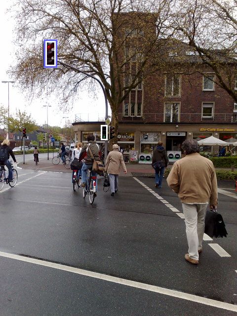
SUBMISSION TO IEEE-TCSVT - SPECIAL ISSUE ON VIDEO ANALYSIS ON RESOURCE-LIMITED SYSTEMS                                                          2

respond to voice commands for control. Many such works
have been reported at the Conference series on Computers
and Accessibility (ASSETS), Computers Helping People with
Special Needs (ICCHP), Human-Computer Interaction (HCI),
and other relevant conferences.
   An early system that detects traffic lights was presented
in 2004 by Aranda and Mares [9]. It used a portable PC
in a backpack featured with a digital camera and a pair of
auriculars. The mobile system ‘Crosswatch’ [10] helps pedes-          Fig. 1. Program usage: pedestrian standing at the traffic light pole holding
trians at traffic intersections with zebra crossings orientate        the mobile device in an upright position
themselves in the correct direction. In that work a prototype
was developed to run with interactive frame rates on a Nokia
camera phone. There also exist options for maintaining the            with when detecting pedestrian lights are discussed. Also, the
mobility of sightless people in an indoor environment. In             German pedestrian lights used in our design and field tests are
[11] a mobile navigation system is presented, which uses              specified.
special color markers to guide the user in a prepared indoor
environment. Traffic light detection is not only helpful for          A. Program Usage
pedestrians but also an important task for driver assistance             To use the program we assume that the pedestrian knows
systems. In [12] the traffic light detection is used for estimating   the path to walk. For instance these paths are trained by
crossroads to give the driver additional guidance information.        orientation and mobility specialists to improve skills to walk
Another vision-based traffic light detection system is presented      independently with a white cane and to get aware of the
in [13], where a static camera position is however assumed to         surroundings and their orientation.
simplify the detection approach.                                         At traffic intersections the orientation and mobility special-
   This paper is an extension to our previous work [14]               ists usually teach their clients locations of the traffic lights
of single frame analysis to video analysis and time-based             with the acoustic or haptic signals. Nevertheless, without those
verification. To our best knowledge, this work is the first           attached signals the pedestrian has to know the location of the
prototype of traffic light analysis reported in the literature,       pole of the traffic light at his side of the street. To use the
which works on the basis of a mobile phone and thus has               traffic light detection the pedestrian has to be in range of the
the potential of being used by visually impaired people.              traffic light pole (see Fig. 1).
In addition to the overall system architecture, we need to               To get the traffic into field of view the mobile device is
carefully design all system components to cope with the very          held in an upright position in an approximate direction of the
limited resources of current mobile phones on the one hand            traffic light on the other side of the street. Since the user only
and to achieve sufficient performance in both accuracy and            knows an approximate direction the mobile device may be
time on the other hand. In particular, the video analysis and         panned slowly a few degrees left or right until the device tells
time-based verification introduced in this paper substantially        the user that a traffic light has been detected. Furthermore,
improves the performance of traffic light identification.             the user may take a few steps left or right to get another
   The remainder of this paper is organized as follows. In            perspective.
Section II, we concretize the external restrictions and specify          An example of the program usage is shown in
the challenges and problems of real world conditions. Fur-            a demonstration video on the authors’ website at
thermore, we define the design of traffic lights that should          http://cvpr.uni-muenster.de/research/pedestrianlights.
be detected. The system architecture is presented in Section
III. We discuss the used mobile device of the prototype and
give further information about the image/video databases,             B. Real World Conditions
which we generated for training and testing purpose and made
                                                                         The development of a mobile vision system to detect pedes-
publicly available. Thereafter, the four steps of the algorithm
                                                                      trian lights very accurately is challenging due to several real
are described: localization (Sec. IV) and classification (Sec. V)
                                                                      world conditions. The chosen mobile capture device limits the
on single frames of the video stream, the extension to video
                                                                      possibilities of computer vision algorithms in several aspects:
analysis (Sec. VI), and time-based verification (Sec. VII).
In Section VIII we give example results and a quantitative               1) The resolution of the capture device is relatively low.
performance assessment of our traffic light detection approach.          2) Mobile devices often provide only poor image quality,
Possible extensions are outlined and conclusions are given in                e. g. falsified colors and unsharpened images due to
Section IX.                                                                  automatic white balance and auto focus.
                                                                         3) Computation power and memory resource are re-
                                                                             stricted.
                II. P ROBLEM S PECIFICATION                           Not only the capture device, but also the objects to be captured
   In this section we discuss how to use the program on               impose restrictions by design and location:
the mobile device to get traffic lights into field of view.              4) Pedestrian lights have different appearances in differ-
Furthermore, the problems and the restrictions one is faced                  ent countries and even for different manufactures.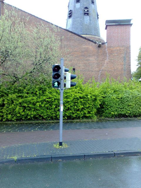
SUBMISSION TO IEEE-TCSVT - SPECIAL ISSUE ON VIDEO ANALYSIS ON RESOURCE-LIMITED SYSTEMS                                                                       3

           (a)                       (b)                        (c)                      (d)                         (e)                         (f)
Fig. 2. Challenges of detecting traffic lights in images: (a) minimal distance, (b) maximal distance, (c+d) two traffic lights, (e) occlusion, and (f) rotation
(from [14])

           (a)                         (b)                          (c)                                   (a)            (b)            (c)
Fig. 3.   Difficult illumination: (a) dusk, (b) frontlighting, and (c) night     Fig. 4. Examples of pedestrian light design in Germany: (a) two lights,
                                                                                 (b) three lights, (c) three lights and an additional ”please wait” sign

   5) The distance to the pedestrian lights could vary between
                                                                                 GPS signal of the mobile phone. The necessary adaptations
      approximately 4 and 24 meters. Therefore, the scale of
                                                                                 will be discussed in Section IX.
      a traffic light in an image is very small (see Fig. 2(a)
                                                                                    Our prototype system was trained to detect pedestrian
      and (b)).
                                                                                 lights that occur in most German cities (see Fig. 4). For the
   6) There may be many traffic lights in the image but only
                                                                                 remainder of this paper the following features of a pedestrian
      one is crucial (see Fig. 2(c) and (d)).
                                                                                 light are assumed to be valid preconditions:
Sight and light conditions may complicate the traffic light                         1) Shape: rectangular with aspect ratio of 1/2, 1/3, or 1/4.
detection:                                                                          2) Color arrangement: at the bottom there is one green
   7) Traffic lights can be temporarily occluded by vehicles                            light, at the top/middle there are one or two red lights.
      (see Fig. 2(e)).                                                                  At the top there is an optional blinking white light, but
   8) Traffic lights could be hardly visible in bad weather                             in our approach we ignore this light.
      situations like fog, heavy rain or snowfall.                                  3) Circuitry: either red or green light is switched on.
   9) The illumination condition varies between night and                           4) Background: the majority of the traffic light is dark.
      daylight. Thus, the captured colors of one traffic light                      5) Design: possible shapes of the green or red lights are
      depend on the capture time (see Fig. 3).                                          limited.
Finally, the user of the system could hold the mobile capture                       6) Installation: mounted at a vertical pole at a height of
device in an unfavorable position:                                                      approximately 2.15 meters and a distance between 4 and
  10) The image could have been captured with a non-                                    24 meters.
      neglected rotation (see Fig. 2(f)).
                                                                                                  III. S YSTEM A RCHITECTURE
   Problems related to camera failure and awkward ambient
light situations will not be discussed because it would go                          Our traffic light detection pipeline (see Fig. 5) consists of
beyond the scope of this work. Furthermore, awkward weather                      two concurrent steps and an additional step that combines
conditions are excluded.                                                         them. In the first concurrent step we identify the crucial pedes-
                                                                                 trian light in the field of view in the recent frame of the video
                                                                                 stream. It consists of localization followed by classification. In
C. Specification of Pedestrian Lights in Germany                                 the localization step we try to filter all the image regions out
   Due to the different appearances of pedestrian lights in                      that may contain traffic lights. The classification step decides
different countries or, even to some extent, cities, we restrict                 which regions contain pedestrian lights and which light is
our system to detect one chosen pedestrian light design. It                      crucial to the user.
should be possible to adapt to other designs and choose the                         The video analysis concurrently computes the crucial light
correct pedestrian light recognition system according to the                     location independent from the traffic light identification. For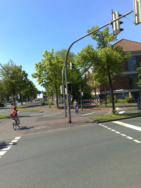
SUBMISSION TO IEEE-TCSVT - SPECIAL ISSUE ON VIDEO ANALYSIS ON RESOURCE-LIMITED SYSTEMS                                                                     4

     Captured                             Identification
      Frames
                                               Localization                       Classification                              Time-Based
                      t0         ti                                                                                           Verification
          ...

                                                 Sec. IV                                Sec. V

                      t i-1                                                                                                                 “Green”
                                                             Video Analysis
                              t i-1,t i
                       ti
                                                                   Sec. VI                                                       Sec. VII

Fig. 5. Overview of the traffic light detection pipeline. On the left the input frames of the live video stream are presented. In the middle the single frame
analysis (top) and the extension to video analysis (bottom) are shown. At the right both results are compared and a feedback is generated.

this purpose the location of the crucial light in the previous                  B. Pedestrian Light Databases
frame is used to track its location in the most recent frame.                      We have built up two databases for the training and testing
   Time-based verification helps us improve the pedestrian’s                    purpose. One is holding images and the other is holding video
safety. Since we expect the crucial light locations computed                    sequences. Both contain pedestrian crossings with traffic lights
by different approaches to be similar this verification step                    and were captured from positions where pedestrians have to
compares the results of the concurrent steps. After a short                     wait for a green signal. Both databases are publicly avail-
period of successful comparisons a feedback for the user is                     able (at http://cvpr.uni-muenster.de/research/pedestrianlights)
generated.                                                                      for the research community.
                                                                                   A ground truth segmentation was made manually, storing
                                                                                all visible pedestrian lights. Furthermore, the crucial light is
A. Prototype System                                                             marked and the phases of the traffic lights (red or green) are
                                                                                given. In Table I the statistics of the databases are presented.
   As a proof of concept a prototype system was developed for
                                                                                The total number of images is shown, which is divided into
a Nokia N95 mobile phone. In the community of blind people
                                                                                the number of images with a crucial red and green light,
Nokia mobile phones are very common due to the large variety
                                                                                respectively, and the images without a crucial light.
of available software, e. g. screen readers, mobile reading and
                                                                                   The number of images without a crucial light is composed
shopping assistants.
                                                                                of the images without any traffic light and the images with at
   The N95 is equipped with a 330MHZ ARM processor and
                                                                                least one traffic light, but without a crucial one.
18Mb of available RAM. A built-in autofocus camera takes
                                                                                   Furthermore, in each database there are images with a dan-
photographs with up to 5MP. This device offers three capture
                                                                                gerous constellation, i. e. a crucial red light and an additional
modes:
                                                                                green light.
   1) Take photographs (up to 2582 × 1944) automatically                           The video database is made up of 14 image sequences.
      when the previous one is finished.                                        Each sequence represents a video stream with approximately
   2) Use the video stream with a resolution up to 640 × 480.                   8 frames per second and between 99 and 853 images.
   3) Take the viewfinder video stream with 320 × 240
      resolution. It is the stream that is shown on the display                          IV. L OCALIZATION OF P EDESTRIAN L IGHTS
      while recording videos or taking pictures.                                   The localization approach presented in this section can be
Due to the preparation time between two photographs, mode 1)                    considered as filter and refinement operations on single frames
cannot provide an interactive facility, even with a low capture                 of the video stream. As mentioned before, traffic lights have
resolution. The video stream 2) is encoded in YUV 420 planar                    specific features (i. e. shape, arrangement, circuitry, design,
format, which has the major drawback that only every fourth                     background, installation). All these features could be used in
pixel contains the correct color value (luminance). As we will                  a special filter algorithm to localize traffic light candidates.
see later we are in need of the correct color values during                        Although a parallel combination scheme of the used filters
the localization (Sec. IV-A). Our work is directly based on                     can achieve a high accurate recognition rate, i. e. high relia-
the detection of the red and green traffic light colors. Thus,                  bility, the computational power usage would be too much to
the RGB color model is more intuitive and we use the video                      ensure interactivity. Note that it is much faster to verify if
stream of the viewfinder 3), which provides this RGB data.                      a feature is valid for a specific candidate than to inspect all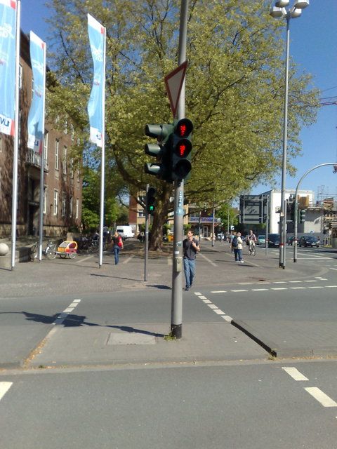
SUBMISSION TO IEEE-TCSVT - SPECIAL ISSUE ON VIDEO ANALYSIS ON RESOURCE-LIMITED SYSTEMS                                                  5

                            TABLE I
 G ROUND TRUTH STATISTICS OF THE IMAGE AND THE VIDEO DATABASE         itself). Another is located along the red color and the rest of
                                                                      the samples is introduced by noise. So we estimate a Gaussian
                                      image      video                mixture model in 3D with four contributions: black cluster,
                        #            database   database
                  images (total)       501        5635                gray cluster, red cluster, and noise cluster (see Fig. 7(b)). Since
                images with red                                       the most significant colors to detect red lights should be the
                   crucial light       309       3822                 red color, we only keep the Gaussian distribution of the red
              images with green
                   crucial light       184       1675
                                                                      cluster (see Fig. 7(c)).
                 images without                                           The green color samples (see Fig. 7(d)) are distributed
                  a crucial light       8         138                 in three significant portions. Similar to the red distribution
               images without a                                       we estimate a Gaussian mixture model in 3D with three
                crucial light but       5         20
              with another light
                                                                      contributions. One cluster is near the gray axis of the RGB-
                 images without                                       cube and another cluster contains values with low intensities
                any traffic light       3         118                 (see Fig. 7(e)). Only the remaining cluster contains the green
            images with dangerous                                     colors that occur in the lamps of the traffic lights. Thus, only
                  constellations        9         127
                                                                      this cluster of the Gaussian distribution is kept for the green
            images with more than
                one traffic light      165       4262                 light (see Fig. 7(f)).
                red lights (total)     424       6891                     (2) Design the filter rules: Here we only discuss the color
              green lights (total)     244       2888                 filter for the red traffic lights; similar filter rules apply for
                                                                      the green traffic lights. The Gaussian distribution of the red
                                                                      cluster is defined by its mean color µ = (0.48, 0.06, 0.07)
possible image regions according to the special feature. In this      and the three eigenvectors v1 , v2 , and v3 corresponding to the
section we thus present an approach to localizing possible traf-      eigenvalues λ1 = 0.0590, λ2 = 0.0032, λ3 = 0.0005.
fic lights in low resolution images in a sequential architecture          A color c = (r, g, b) is considered as red traffic light color
(see Fig. 6). This architecture provides interactivity, but also      if and only if the following three rules are fulfilled:
a high reliability. Furthermore, it is robust against the scale of                 Ired (c) := c · v1   ≥   thred,1                  (1)
traffic lights and also against rotation (to some degree).
                                                                                        (c − µ) · v2    ≤   thred,2 · Ired (c)       (2)
   As a first step of our localization procedure a red and a green
color filter are used (Sec. IV-A). After a connected component                        |(c − µ) · v3 |   ≤   thred,3                  (3)
analysis we compute the size and the circuitry to reduce false        It means that the red intensity Ired , which is the distribution
positives (Sec. IV-B). In Section IV-C we explain the next            along the dominant axis, should be lower bounded (Eq. (1)).
step: examination of the background color. The optional last          Furthermore, the distance to the red intensity axis along v2
step is a shape-based segmentation of the pedestrian light (see       should be limited toward the gray diagonal (Eq. (2)). The third
Sec. IV-D).                                                           rule is motivated by the observation that the distribution along
   At the end of this section we optimize parameters of the           v3 is very tight. More precisely, the distance of c along this
traffic light localization (see Sec. IV-E) and investigate the        direction is thresholded (Eq. (3)).
rotational robustness (see Sec. IV-F).                                   The resulting red traffic light region in the RGB-cube is
                                                                      wedge-shaped with missing apex. In Figure 7 examples are
A. Red and Green Color Filter                                         shown for the red 7(c) and the green 7(f) color clusters with
                                                                      thresholds th1 = 0.20, th2 = 0.25, and th3 = 0.07.
   The most significant feature of traffic lights is the bright
                                                                         (3) Optimize parameters: The image database was divided
color of the lamps. Due to the increased use of LED lights in
                                                                      in two disjoint sets, the training and the validation set. To
traffic lights the color is very specific. In this step we search
                                                                      optimize the parameters we apply the whole localization
for such colors in the region of interest, i. e. the limited region
                                                                      approach on the training data with different parameter settings
when the vertical line filter is applied or otherwise the whole
                                                                      and take the best (see Sec. IV-E).
image. Therefore, the color of each pixel is checked to fulfill
                                                                         The responds of the color filters are represented by a binary
some filter rules. We use the RGB color space, since this is the
                                                                      image where 1 corresponds to a positive filter result and 0 to
default color space on most mobile devices and a conversion
                                                                      a pixel, which is not part of a traffic light lamp according to
to another color space is time-consuming.
                                                                      its color. As a post-procession step, we apply a morphological
   Figure 7 shows a plot of red (a) and green (d) traffic light
                                                                      closing and compute the connected components.
colors, which are extracted from the ground truth. In the
following we explain how to establish the color filters for
the traffic lights based on the extracted colors in three steps:      B. Segmentation using Size and Circuitry
(1) analyze the color distribution of ground truth, (2) design           During the last step we have identified pixels that have the
fast and valuable parameterized filter rules, (3) optimize the        desired color to be part of a traffic light lamp. These pixels
parameters.                                                           are already grouped to connected components.
   (1) Analyze the data: One portion of the red color samples            We assume that the crucial traffic light is between 4 and 24
in Figure 7(a) is distributed along the gray axis of the RGB-         meters away (see Sec. II-B). In our setting with a small and
cube (one cluster near black and one cluster along the axis           fixed focal length of the mobile cameras this range corresponds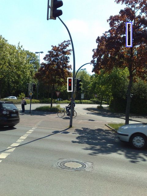
SUBMISSION TO IEEE-TCSVT - SPECIAL ISSUE ON VIDEO ANALYSIS ON RESOURCE-LIMITED SYSTEMS                                                                         6

            Image                              Connected                              Light Spot                    Traffic Light Locations
                                               Components                             Candidates                          and Regions

                           Sec. IV A                              Sec. IV B                              Sec. IV C
                    Red / Green Color Filter                Size / Circuitry Filter                Background Color Filter

Fig. 6. Sequential combination scheme for localization from left to right: (1) input color image, (2) color filter response in green and red, resp., (3) color
regions after pruning, (4) dark filter response in black, search region in blue, initial bounding boxes in light blue, (5) localized traffic lights.

                                        (a)                                       (b)                                        (c)

                                        (d)                                       (e)                                        (f)

Fig. 7. Red (a) and green (d) traffic light colors from ground truth. Clustering of the red (b) and green (e) samples visualized by the mean colors of the
respective cluster. Complete filter for red (c) and green (f) colors.

to a width of the traffic light between 2.5 and 15 pixels. Due                          C. Background Color Filter
to the known possible aspect ratios of 1/2, 1/3, or 1/4 (see                               The result of the last step are connected components of
Sec. II-C) we also know the possible corresponding heights.                             adequate sizes and colors. We know that the green lamp under
These parameters can be utilized to filter out regions that are                         a red light is switched off and vice versa. This fact enables
too small or too huge by thresholding the size of the connected                         us to implement a background filter, which inspects the image
components.                                                                             region under a red light candidate and above a green light.
                                                                                        In our system we defined the search region to have the same
   Due to reason of circuitry we know that exclusively the                              size as the connected component it belongs to (half height if
red or the green light is switched on. Connected components                             two red components were merged). If there are no dark pixels
featuring red and green pixels cannot be part of a valid traffic                        within this appropriate search region, it allows us to refuse
light. Furthermore, vertical neighbored connected components                            this candidate.
of different colors represent dangerous constellations. Thus,                              In our implementation this filter is simply defined as
all such candidates are refused.
                                                                                                   I(p) ≤ thred, dark   or resp.      I(p) ≤ thgreen, dark   (4)
   As a post-processing step we melt two red connected                                  where I(p) = (R(p) + G(p) + B(p)) /3 is the intensity of
components that are vertically neighbored, since a red light                            the pixel p. Furthermore, thred, dark and thgreen, dark are darkness
may consist of two lamps. The size of the melted components                             thresholds. The result of this step is a so-called initial bounding
are again checked against the size constraint.                                          box. It is a box around each traffic light candidate. The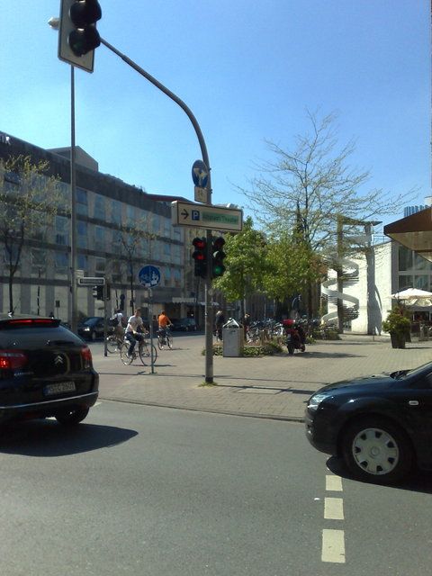
SUBMISSION TO IEEE-TCSVT - SPECIAL ISSUE ON VIDEO ANALYSIS ON RESOURCE-LIMITED SYSTEMS                                                                                                    7

candidate is given by the connected components of the color                          100                                                             100

sample and the search region of the background color filter.                          80                                                              80

                                                                                      60                                                              60

                                                                       Recall in %

                                                                                                                                       Recall in %
D. Shape-Based Segmentation
                                                                                      40                                                              40

   We have already localized possible traffic light candidates,
                                                                                      20                                                              20
by their lamp color, size, arrangement and background color.
In this last step we aim to segment the traffic lights according                       0       20     40            60      80   100                   0   20   40            60   80    100
                                                                                                       Precision in %                                            Precision in %
to their rectangular shapes. Firstly, we assume that the rotation
                                                                                            (a)                                (b)
angle of the capture is fairly low (about ±10o ). A traffic light
                                                                        Fig. 8. Recall and precision for the localization of (a) red and (b) green
region should fulfill the following constraints:                        traffic lights (from [14])
   1) Traffic light and background are contained.
   2) Aspect ratio is between 1/4 and 1/2.
   3) Many pixels (e.g. 80%) are either light or background.               In the following we optimize the parameter groups for red
   4) Width of the region lies between 2 to 15 pixels.                  and subsequently for green traffic lights using the training
To ease the computation we consider axis-parallel rectangular           set of our ground truth database. Finally, we validate these
regions only. The task can be modeled by an optimization, like:         optimizations on the validation set.
Find the region of maximal size, which fulfills all constraints.           1) Optimize Parameters for Red Traffic Lights: The missing
   This optimization is however time-consuming, since many              of a red sign could cause serious problems. So our optimiza-
possible regions have to be considered for each traffic light.          tion criterion is to maximize the precision with a bounded miss
Therefore, in our implementation we use a fast but subopti-             rate. Fig. 8(a) shows the performance of the investigated red
mal region growing approach. The initial bounding box (see              parameter settings. We claim a recall1
Sec. IV-C) is first simultaneously expanded to the left and the                                                          R = TP/(TP + FN )                                              (5)
right. We stop, if the left or right border consists of too many
non-background pixel. After computing the vertical boundary,            of at least 75% and choose the setting with the best precision2
we apply an analogous technique to find the top and the bottom
                                                                                                                         P = TP/(TP + FP ).                                             (6)
of the traffic light.
   Even using a suboptimal but fast optimization strategy, this         The result of our optimization are the parameters thred,1 = 0.3,
last step decreases the performance so that an interactive              thred,2 = 0.15, thred,3 = 0.028, thred, dark = 0.19. With a recall
application is impossible on our hardware. Furthermore, the             of 76.0% a precision of 89.5% is achieved. This optimized
computation of the borders is somehow non-robust. Since the             performance is visualized as a black asterisk in the Fig. 8(a).
profit of this segmentation is negligible compared to the com-              2) Optimize Parameters for Green Traffic Lights: The op-
putational costs, we abandon the segmentation step. In future           timization of the green parameter set depends on a bounded
settings the segmentation might be profitable. For instance we          precision. The precision equals 100% if and only if we have
need a segmented region for a model-based verification [14].            detected no false green light. We allow at most 1.5% FP
Therefore, we keep the segmentation as optional step in our             (i.e. P ≥ 98.5%) and choose the parameter vector yielding the
localization pipeline.                                                  best recall. Fig. 8(b) shows the performance of the investigated
                                                                        green parameter settings. The best thresholds of the green
E. Parameter Optimization of Traffic Light Localization                 filter are: thgreen,1 = 0.2, thgreen,2 = 0.15, thgreen,3 = 0.05,
                                                                        thgreen,dark = 0.19. With these parameters we achieve a recall
   In this section the optimization of the parameters of our
                                                                        of about 85.0% (see black asterisk in Fig. 8(b)).
localization approach is discussed. Our traffic light detection
                                                                            3) Validate the Localization Results: As mentioned before,
algorithm depends on eight main parameters, four color pa-
                                                                        the validation set consists of 201 images, which are not used
rameters in each case (red and green light, resp.). These two
                                                                        during the parameter optimization. We validate the localization
parameter groups are optimized separately. In our experiments
                                                                        approach with the optimized parameters on all visible traffic
we subsample each parameter into 10 steps, getting 104 differ-
                                                                        lights in the images of the validation set. For all red lights of
ent parameter settings for each color. With our ground truth,
                                                                        the validation set we achieved a recall of R = 71.8% and a
we measure the quality of the setting by counting the number
                                                                        precision of P = 87%. For the green traffic lights a recall of
of correctly detected traffic lights (TP ), falsely detected traffic
                                                                        R = 83.3% and a precision of P = 92.6% were achieved.
lights (FP ), and missed traffic lights (FN ). A traffic light is
                                                                        The true positives, false positive and false negatives are listed
detected correctly if the initial bounding box is completely
                                                                        in Table II.
in the segmented bounding box from ground truth. For this
                                                                            Overall, false negative and false positive detections occur
comparison the segmented box from ground truth is extended
                                                                        for 90 of the 267 traffic lights in the validation set of 201
by 2 pixels in each direction to prevent small deviations.
                                                                        images, which is equal to an error of 33.7%. This error seems
   We have divided the image database into two disjoint
                                                                        to be very high. It is mostly caused by very small, undetected
sets. The first set (300 images) is used for training. With
the remaining 201 images we verify the performance of our                            1 also   called true positive rate
approach.                                                                            2 also   called positive predictive rate or occasionally, detection rate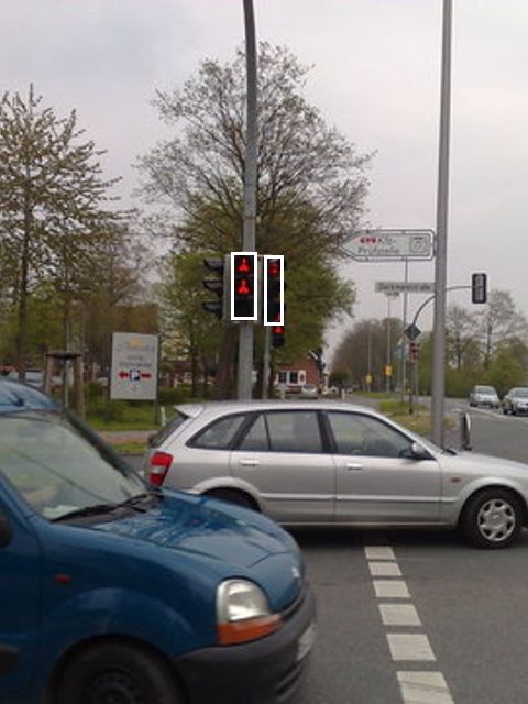
SUBMISSION TO IEEE-TCSVT - SPECIAL ISSUE ON VIDEO ANALYSIS ON RESOURCE-LIMITED SYSTEMS                                                                                                          8

                              TABLE II
   T RUE POSITIVES , FALSE POSITIVES AND FALSE NEGATIVES OF THE                                                                       Traffic Light                      Crucial Traffic
  LOCALIZATION STEP FOR 177 RED AND 90 GREEN TRAFFIC LIGHTS OF                                                                         Locations                             Light
           THE VALIDATION SET CONSISTING OF 201 IMAGES
                                                                                                                                                         Sec. V A
                                                                                     red           green                                              Selection Filter
                                                            true positive            127            75
                                                           false positive            19              6
                                                           false negative            50             15                 Fig. 10. Sequential combination scheme for classification. Selection of the
                                                                                                                       crucial traffic light in the image
                                                     100
                 Count of True Positive Detections

                                                      80

                                                      60                                                                  In this section we describe how to select the traffic light
                                                      40                                                               that is crucial for the pedestrian (Sec. V-A). Furthermore,
                                                      20
                                                                                                                       the performance of the identification approach is presented in
                                                       0
                                                                                                                       Section V-B. At the end of this section some example results
                                                        -60 -50 -40 -30 -20 -10 0        10 20     30   40   50   60
                                                                        Rotation Angle in Degree                       are shown and discussed (Sec. V-C).
Fig. 9. Rotational robustness of the localization approach for red traffic lights
(similar for green lights)
                                                                                                                       A. Selection of the Crucial Light
                                                                                                                          By reason of perspective, the important traffic light should
traffic lights in the background, which were mostly not the                                                            be the biggest and highest of all traffic lights in the image.
crucial light. To obtain a deeper insight we investigated the                                                          These two simple criterion are used to select the crucial traffic
crucial light detection error ratio. The error of missing the                                                          light. More precisely, we report a traffic light candidate TLCi
crucial red traffic lights is about 3.8% (5 lights missed from                                                         as crucial if all of the following constraints are true:
132 crucial lights). In comparison 8 from 66 crucial green
                                                                                                                         •   TLCi is the broadest traffic light
lights have been missed (approx. 12.1%). Consequently, the
                                                                                                                         •   TLCi has got the smallest distance from the top of the
error of missing the crucial traffic light is considerably lower.
                                                                                                                             image
                                                                                                                         •   No other traffic light has a distance from the top of the
F. Rotational Robustness                                                                                                     image similar to TLCi
   Experiments on the rotational robustness showed that a                                                                 For the third point we report two traffic lights to have a
rotational angle of ±10o only slightly affects the performance                                                         similar distance from the top of the image if the difference is
of our approach (see Fig. 9). For these tests we have rotated the                                                      less than 10 pixels.
images in both directions with linear subsampling. We report                                                              The color of such a traffic light TLCi is obvious since the
the angular range in which the result remains stable.                                                                  region contains exactly one type of traffic light color, either
   Including all images (training and validation set) in this                                                          red or green. In the case that there exists no TLCi for which
test scenario, we can identify 328 (i. e. 77.4%) of the red and                                                        all constraints are fulfilled, we have found no pedestrian light.
206 (i. e. 84.4%) of the green traffic lights with no rotation.                                                        There could be different failures. The catastrophic error is that
If the images are rotated by maximal ±10o , we recognized                                                              a green light is reported during a red phase. Reporting no
254 red and 180 green traffic lights. This means that the                                                              traffic light or a false red report are errors that abridge the
localization remains stable for 77.4% red and 87.4% green                                                              convenience but do not affect the user’s safety.
lights in comparison to the case with no rotation. There are
several reasons why rotation affects the localization result:
   1) The search region of the background color filter (see                                                            B. Performance of Classification
       Sec. IV-C) contains more (bright) pixels that do not                                                               In Section IV-E we optimized the parameters of the lo-
       belong to the traffic light region. This situation appears                                                      calization based on the recall and precision. In this section
       most when the traffic lights are far away and the search                                                        the performance of identifying the crucial pedestrian light is
       region is small.                                                                                                presented on the training set.
   2) When two red components were merged, the width                                                                      The performance for detecting the crucial traffic light is
       grows by image rotation, so that the size filter (see                                                           presented in Fig. 11 using ROC-curves. Here, the true positive
       Sec. IV-B) may refuse candidates.                                                                               rate is plotted against the number of false positives. Further-
                                                                                                                       more, the standard deviation is visualized by the vertical lines.
         V. C LASSIFICATION OF P EDESTRIAN L IGHTS                                                                     Our optimized parameter setting (the black asterisk) leads to
   The localization procedure (Sec. IV) results in a set of traffic                                                    a stable recognition of the crucial traffic light. As desired the
light candidates TLC1 , . . . , TLCk . In this section we discuss                                                      number of false positives is very small in the case of green
how to select the correct candidate (see Fig. 10) of the current                                                       light detection. We report in 2 cases a wrong crucial green light
frame of the video stream. The features we could use are the                                                           (precision of 98.1%) and keep a recall (i.e. true positive rate)
position and size of the traffic light candidate in the image. If                                                      of 86.3%. The performance of the red traffic light detection is
the segmentation step of the localization pipeline is left out,                                                        similar: We classify in 4 cases false red traffic lights (precision
we use the initial bounding box as segmentation.                                                                       of 97.4%) and achieve a recall of 86.3%.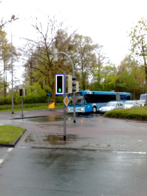
SUBMISSION TO IEEE-TCSVT - SPECIAL ISSUE ON VIDEO ANALYSIS ON RESOURCE-LIMITED SYSTEMS 9
100 100
80 80
True Positive in %
True Positive in %
60 60
40 40
20 20
0 20 40 60 80 100 0 10 20 30 40 50
False Positive False Positive
(a) (b)
Fig. 11. ROC-curve for detecting the crucial (a) red and (b) green traffic light. The light gray markers represent the performance of each parameter set, the
black line the mean values and the vertical gray lines the standard deviations. Black asterisk is the optimized parameter set.
C. Results of Traffic Light Identification vehicles. After a few moments these vehicles will have
Our validation set consists of 201 images, which are not passed the crossing and the detection could repeat.
used during the parameter optimization. We fixed the param- 2) Falsified Colors
eters and applied the approach on this validation set. For red In some situations the automatic illumination correction
traffic lights we yield a precision of 96.5% and a recall of falsifies the traffic light colors. By moving the camera
83.3%. The precision for green traffic lights is 98.3% and the and repeating the traffic light identification approach a
recall is 90.8%. We report 5 wrong crucial traffic lights and result may be given. Even slight movements give the
falsely report no traffic light in 28 of the verification images. camera the chance to readjust the automated camera
This corresponds to an overall miss rate of 16.4%. settings, like white balance and exposure.
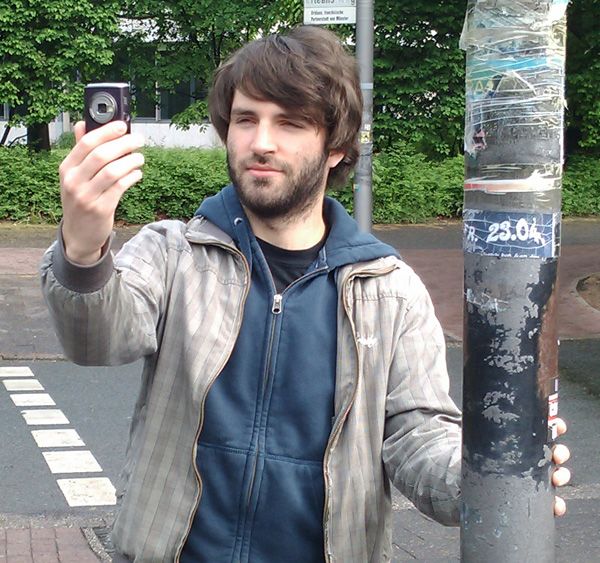
Fig. 12 depicts some results produced with our approach 3) Contradictory Scene
of traffic light identification. Thereby, we put a white frame Two traffic lights close to each other may be contradic-
around all traffic light candidates and an additional blue frame tory (see Fig. 2(d)). In such situations no feedback can
around the reported crucial one. In the first two results (a-b) be given, since a feedback could be very dangerous. By
perfect recognitions are presented, even in dark illumination changing the perspective the scene may be resolved so
conditions (a) or bright traffic light color (b). that a decision is possible.
However, there are still some limitations, which we present 4) Repeating Results
in Figure 12(c-d). If traffic lamps are captured with low In a video stream the same identification result may
saturation (c) the traffic light could be missed. Sometimes the repeat. If this happens a few times successively it will
scene is contradictory (d). increase the certainty that it is correct.
Sometimes noisy objects are detected as traffic light candi- To make use of the video stream we want to track the crucial
dates (see Fig. 12(e-f)). Objects on trees (e) could be identified light between consecutive frames to improve the performance
as traffic light candidates. Such situations are much more of the system. The tracking could be used in two different
difficult, since the objects may be placed above the crucial ways: (1) Track the crucial traffic light in the following
traffic light. A template matching could decrease such false frames to save computation time of the re-localization and
positives. Currently, template matching is not integrated in re-classification. (2) Apply the localization and classification
our system. Another situation in which an additional template in every frame, in addition also track the crucial light be-
matching step could be helpful are transversely mounted street tween two consecutive frames. Afterwards, compare the two
traffic lights (see Fig. 12(f)). determined positions of the traffic light. Whereas the first
Some problems (e.g. (d) and (f)) are introduced by a approach improves the interactivity, the second improves the
poor perspective angle and can be corrected by changing the reliability. In our system we choose way (2), the time-based
viewpoint. This is shown in (g-h). In the next section we verification, since false positive detections should be avoided
discuss an extension to the video stream, which among others in any circumstances.
reduces the effect of poor perspective. In our setting the distance between the mobile device and
the traffic light is at least 4 meters. Since we assume that the
user does not change his position very fast and the rotation
VI. V IDEO A NALYSIS
angle is at most ±10◦ , we can neglect the 3D perspective view
The identification of the crucial traffic light in single images changes, scaling and rotation in the tracking approach. Thus,
was described in Section IV and V. The traffic lights in the we only have to deal with translation between two frames and
image were localized and thereafter, the crucial light was we can use motion estimation algorithms to get the position
selected. In this section the traffic light detection is extended of the crucial light in a new frame.
from single images to video streams due to the following For the remainder of this section the objective is to estimate
reasons: a motion vector which defines the translation between two
1) Temporary Occlusion consecutive frames in the proximity of the crucial light. With
Objects that occlude the crucial traffic light are big this vector the location of the crucial light in the new frame is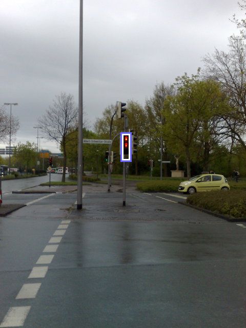
SUBMISSION TO IEEE-TCSVT - SPECIAL ISSUE ON VIDEO ANALYSIS ON RESOURCE-LIMITED SYSTEMS                                                                              10

               (a)                                         (b)                                          (c)                                         (d)

                (e)                                          (f)                                         (g)                                         (h)
Fig. 12. Results of the localization and classification. The found traffic lights are marked with a white border. An additional blue border marks the crucial
light. (a-b) perfect result, the crucial traffic light was located and classified correctly. (c) no traffic light reported due to failure of localization. (d) decision
could not be made due to classification. (e-f) noisy objects. Change of perspective with different result between (g) and (h). More results are presented in [14].

determined easily. Approaches to estimating the motion vector                        were set with the following trade-off. We want to have between
using phase correlation [15] or more complex methods like the                        5 and 10 frames per second to compute the whole approach.
determination of optical flow [16] cannot be used interactively                      Furthermore, the tracking should be subjectively stable. The
on mobile devices due to the need of high computational                              final parameter set was acquired in live field tests of our
burden. To estimate the image difference between two frames                          prototype system: The size of the small areas around the
we thus compute feature points in the first frame around                             points is 5 × 5. We search for the 5 best feature points and
the crucial light location and search corresponding points                           search in a small radius of 30 pixels in each direction for the
in the following frame. An applicable algorithm for motion                           matched position. The displacement vectors are the difference
estimation on hand-held devices was presented in [17], in                            between the old position and the new one. These displacement
which a multi-resolution scheme is used to search features                           vectors are combined to one single displacement vector that
in the image. However, due to the fact that in our system                            describes the image translation. The resulting vector is the
another complex algorithm (for traffic light localization and                        mean vector of all similar displacement vectors if and only if
classification) has to work on each frame, an even faster                            at least 3 displacement vectors nearly have the same values,
approach is needed. For our purpose we use the KLT tracker                           i. e. a maximum Euclidean difference of 4. Otherwise, if less
[18] due to the fact that it detects features that are good to                       than 3 of those vectors have been found the motion estimation
track. We reduced the computational time usage of the tracker                        has failed.
by only searching for good features in a small area around the                           With the presented approached and the given thresholds
crucial traffic light candidate (30 pixels in each direction). To                    a stable motion estimation approach was realized. After this
match the feature points we define the features as the small                         computation we get the location of the crucial traffic light in
fixed-size areas around the points. These features are searched                      the recent frame independent of the traffic light identification
in the second frame in a specified radius around the initial                         step (see Fig. 5).
position of the feature point. We correlate the features by using
the sum of absolute differences.                                                                      VII. T IME -BASED V ERIFICATION
  In our setting we use several thresholds. To estimate good                            In this section we want to verify the results of the concurrent
parameter values we tested different settings. These thresholds                      steps of our traffic light detection system (see Section IV, V
were not optimized by using the ground truth meta-data, but                          and VI). Thereby, the main focus is the reduction of false
SUBMISSION TO IEEE-TCSVT - SPECIAL ISSUE ON VIDEO ANALYSIS ON RESOURCE-LIMITED SYSTEMS 11
TABLE III
positive detections. For this purpose we introduce the state R ECALL AND PRECISION OF THE WHOLE SYSTEM FOR THE VIDEO
queue, which allows a verification over time. DATABASE
We have to combine two results: (1) the identified crucial
red green
pedestrian light from the localization (Sec. IV) and classi- recall 52.4% 55.3%
fication (Sec. V) step; (2) the tracked traffic light location precision 100% 100%
from video analysis (Sec. VI). Based on our observations we
suppose that the locations match if their distance is less than
5 pixels. Four scenarios are possible: VIII. R ESULTS
1) Traffic light identification and video analysis are suc- In this section we want to present results of our traffic light
cessful and the location of the crucial light from identi- recognition system. In particular, we discuss the results of the
fication step and the estimated one of the video analysis traffic light identification on single images in comparison to
match. the additional video analysis and time-based verification.
2) Traffic light identification and video analysis are suc- The state queue for the presented results was configured
cessful, but the locations differ. with SQsize = 10 and SQmin = 5 due to the following reasons.
3) Video analysis succeeds but traffic light identification On the one hand, a feedback should be given within one
step fails (i. e. localization or classification). second (with optimal detection) due to the fact that we want
4) Video analysis fails (i. e. motion could not be estimated). to compute at least 5 frames per second. On the other hand,
These scenarios are mapped to the state queue in the a larger size SQsize of the state queue may store outdated
following way. Case 1) is the only positive. They are mapped feedbacks. With SQsize = 10 and the minimum 5 frames per
to a red or green state, dependent on the current traffic light second the given feedback is (maximal) one second old.
phase of the recent frame. Example results of the whole traffic light detection approach
Although the traffic light identification in the recent frame with applied video analysis and time-based verification are
fails, case 3) is not critical due to the fact that the motion shown in Figure 13, 14 and 15. For visualizing the results the
estimation is successful and the traffic light could possibly be dark box in the images shows the crucial traffic light that was
verified in the following frames. These results are represented detected in the localization and classification approach. The
by a black state. blue box represents the result of motion estimation. Below
The remaining two cases are critical and mapped to a each image the state queue is shown with its color states and
blue state. In terms of case 4) it is impossible to verify the feedback appears in the bottom area.
the identification result, due to the failed motion estimation, In the introduction of the paper we declared our two main
which represents the basis of our verification approach. Thus, objectives: reliability and interactivity. In the following we
we are not sure enough if the detected pedestrian light is discuss the results with regard to these two objectives. A
the crucial one. If case 2) occurs, the identification or the short video that demonstrates the working of our system in
tracking detected a false crucial light. For example, the motion real environment can be found at http://cvpr.uni-muenster.de/
estimation may point to the recent crucial traffic light in red, research/pedestrianlights.
but the identification result may point to a green light in the
background.
With these states we can verify the traffic light detection A. Reliability
over time. For this purpose we build a queue that stores the As mentioned before, the reliability is the most important
states of the last SQsize combination results, called state queue. design criterion for the traffic light localization and classi-
It differs from a normal queue in the following way. Access fication in single images. We have optimized the parameter
to all elements is allowed. When the queue is full and a new values to prevent false positive green light detections in
state is pushed the oldest element is removed automatically. any circumstances and therefore to achieve a high precision,
A feedback to stay (color c =red) or walk (color c =green) whereas dangerous feedbacks were reduced to a minimum.
is given if and only if the crucial light of color c is identified Moreover, we achieved a high recall for red traffic lights so
in the recent video frame and the following conditions are that red lights would not be missed.
fulfilled: With additional video analysis our system reached a better
1) At least SQmin correct traffic light detections with the precision for green and red traffic lights, but a lower recall (see
same color c are required, counted from the last inserted Table III). With video analysis and time-based verification we
red or green state. observed 0 false positive feedbacks in 5635 frames, neither
2) These occurrences must not be interrupted by a blue for red nor for green traffic lights, i. e. the system responses
state. very safely. The drawback of this reliability improvement
3) Between these occurrences color c must not switch from is the number of false negative feedbacks, which limit the
red to green or from green to red. interactivity (see Sec. VIII-B).
If at least one of the conditions is not fulfilled, no feedback Table IV shows another representation of the results. The
is given and the pedestrian should wait for a feedback. bold printed results present the reliability improvement of
Consequently, black states do not directly exert influence on the system with and without video analysis and time-based
the state queue. Only when there are more than SQsize −SQmin verification. In 93.1% of all images neither the single image
black states no feedback is given as a result of these states. analysis nor the video analysis gave a false positive feedbackSUBMISSION TO IEEE-TCSVT - SPECIAL ISSUE ON VIDEO ANALYSIS ON RESOURCE-LIMITED SYSTEMS 12
TABLE IV
C OMPARISON OF FALSE POSITIVE GREEN LIGHT DETECTIONS BETWEEN normally provides a feedback within 2 seconds, the traffic light
VIDEO ANALYSIS AND SINGLE IMAGE ANALYSIS . T HE BOLD MARKED identification normally gives between 4 and 8 feedbacks in a
NUMBERS SHOW THE IMPROVEMENT OF VIDEO ANALYSIS .
second.
6.9% OF THE DETECTED GREEN LIGHTS WERE FALSELY DETECTED WITH
SINGLE IMAGE ANALYSIS AND REJECTED BY VIDEO ANALYSIS . T HE From the 14 available sequences there are 2 which seem
VIDEO ANALYSIS DID NOT PRODUCE EXTRA ERROR (0%) WHEN THE to be outlier (see Table V). Except from sequence 1 and 4
SINGLE IMAGE ANALYSIS CORRECTLY DETECTS GREEN LIGHTS .
there are small means and standard deviations. Furthermore,
single images single images the maximum frame count between two feedbacks is less than
not false positive false positive 38.
video sequences Sequence 1 and 4 indicate that there are situations in which
not false positive 93.1% 6.9% our system does not provide an interactive feedback. After
video sequences
false positive 0% 0% 397 frames (sequence 1), i. e. between 40 and 80 seconds, the
user would not get a response of the system. This is due to
fast changing false positive and false negative detections and
of a green crucial light. In 6.9% the single image analysis furthermore, due to the reactions of the motion estimation;
falsely detected a green crucial traffic light, whereas the see Figure 15 for an example of sequence 1. It is important to
video analysis rejected it. Since the precision is 100%, both note that although the interactivity is decreased in this case, no
remaining values are 0%. It means that the video analysis false positive feedbacks are given. This is a correct decision
did not produce extra error when the single image analysis for safety reasons related to our main design criterion.
correctly detects green lights. Moreover, there is no image, in Figure 14 (seq. 4) shows another case of benefit of video
which both detected a false candidate. analysis. In (b) and (c) false crucial green lights were identified
This power of temporal analysis was not only observed in and refused by the video analysis. The false candidate of (c)
working with the video database, but also in many additional is even verified in (d) once, which is refused by time-based
tests under real conditions using the prototype system. In verification. Without video analysis 3 false feedbacks would
numerous such field tests we did not observe a single situation have been given (a-d). Instead, our system decides to remain
where a false positive response was produced. without feedbacks and to wait for more reliable detections.
An example showing very good detection results is shown
in Figure 13. During the phase switch no feedback is given IX. D ISCUSSION AND C ONCLUSIONS
for SQmin frames.
Figure 14 shows a situation in which the system would A system was presented for detecting traffic lights for
have failed without video analysis and verification. In 3 of visually impaired pedestrians on a mobile device. As a proof
the 6 frames the system would have given a feedback to walk, of concept a prototype designed for German pedestrian lights
although the crucial light is red. Due to video analysis these was developed for a Nokia N95 mobile phone and tested in real
false positive responses are prevented. environment. It runs with about 5 to 10 frames per second, so
that in general a feedback is given in less than a few seconds.
We tested this prototype in several situations, e. g. rainfall,
B. Interactivity snowfall, dusk, frontlighting, etc. On the one hand we did
The second main objective of our system is interactivity. not observe a false positive feedback, but on the other hand
We measure the interactivity by the number of feedbacks of the amount of missed traffic lights increased very much. In
the system. With video analysis and time-based verification our field tests the power consumption turned out to be not a
feedbacks are given as described in Section VII. Each result matter of fact. The mobile device with our prototype system
of the bare traffic light identification step is interpreted as was active for about 2 hours without running out of battery.
feedback in our interactivity results. Several challenges have been tackled: low image quality
The additional steps in our system with temporal analysis and resolution, restricted computational power and memory
potentially reduce the interactivity, since we have to wait for at resource, scalability, rotational robustness, temporary occlu-
least SQmin verified frames to give a feedback (see Fig. 13). sion, and the selection of the crucial traffic light. In particular,
Furthermore, if the motion estimation fails, the verification the temporal analysis turns out to be powerful in enhancing
will start from scratch. the system performance. Overall, a good trade-off between
The interactivity of the system is presented in Table V. interactivity and reliability has been achieved.
There, the number of frames between two consecutive feed- With enough caution, the presented prototype in its current
backs is measured. It shows that the overall frame count state in fact would improve the safety of visually impaired
between two feedbacks is 1.8 in average with a standard pedestrians. For instance, if the user gets the signal to walk,
deviation of 9.2 frames for the system with the additional video he could signalize the drivers his intention to walk by holding
analysis and time-based verification. With our assumption to his white cane on the street in a higher angle that can be seen
get between 5 and 10 frames per second and with a stable by the drivers. With such sort of signalization the user would
traffic light recognition a feedback is normally given within be safer using the prototype than having no information about
2 seconds. The mean interactivity of the bare traffic light the phase of traffic lights.
identification step is similar with 1.1 frames, but the standard Working with devices of limited resources like mobile
deviation is 18 times smaller. Whereas the whole system phones is always an art of making compromises betweenYou can also read