ROBOTIC FABRICATION OF TOPOLOGY OPTIMISED CONCRETE COMPONENTS WITH REUSABLE FORMWORK - caadria 2022
←
→
Page content transcription
If your browser does not render page correctly, please read the page content below
ROBOTIC FABRICATION OF TOPOLOGY OPTIMISED CONCRETE
COMPONENTS WITH REUSABLE FORMWORK

A design-to-fabrication workflow to manufacture freeform multi-branching concrete
structures

                YIYAO GUO1, YANG LUO2, SIHAN WANG3, YING YI TAN4 and
                KENNETH TRACY5
                1,2
                   Zhejiang University, 3,4,5Singapore University of Technology and
                Design.
                1
                 guoyiyaoelina@163.com, 0000-0002-6346-6612
                2
                 3170105017@zju.edu.cn, 0000-0001-5449-5799
                3
                 sihan_wang@alumni.sutd.edu.sg, 0000-0003-1383-6790
                 4
                   yingyi_tan@sutd.edu.sg, 0000-0003-0545-7061
                5
                 kenneth_tracy@sutd.edu.sg, 0000-0002-5143-6053

                Abstract. In this paper, we introduce a design-to-fabrication
                workflow to create topology optimised concrete components by clay
                printing a temporary mould and simultaneously casting concrete into it.
                Our fabrication approach addresses the United Nation's Sustainability
                Development Goal (SDG) 12 of reducing waste in construction by
                employing the phase changing properties of clay, allowing this natural
                resource to be broken down and reused for subsequent projects. We
                implemented our workflow in the design and fabrication of a resilient
                infrastructure that responds to SDG 9 - an urban furniture that braces
                large trees during high-speed typhoon winds and serving as a bench for
                locals to rest under the tree. This paper documents our workflow with
                considerations of its overall workability, material properties and
                fabrication efficiency. We showcase our final prototype and discuss the
                feasibility and challenges of this approach in fabricating complex
                freeform components on a large scale.

                Keywords. Robotic Fabrication; Topology Optimisation; Freeform
                Concrete; Reusable Formwork; SDG 9; SDG 12.

1. Introduction

Rapid urbanisation over the past few decades has led to construction waste becoming
an increasingly prominent problem. In response, both practice and academia have
moved towards adopting algorithmically driven modelling and robotic fabrication to
design structurally efficient building components that can be manufactured with less
resultant waste respectively (Hauschild & Karzel, 2011). These strategies echo United

POST-CARBON, Proceedings of the 27th International Conference of the Association for Computer-
Aided Architectural Design Research in Asia (CAADRIA) 2022, Volume 2, 91-100. © 2022 and published
by the Association for Computer-Aided Architectural Design Research in Asia (CAADRIA), Hong Kong.
92                                  Y. GUO ET AL.

Nation’s Sustainability Development Goal (SDG) 12 in reducing waste in our modern-
day construction industry (United Nations, 2022).
    The subject of this research is the manufacture of concrete which has often been
used to make building components. Although it serves as a low-cost and structurally
viable building material, fabricating concrete is conventionally a high waste process.
Each component requires a sacrificial mould, typically made from timber or foam, that
attributes 46.7%-73% of costs of the total building project (Agustí-Juan et al., 2017).
These moulds get discarded after the project ends which inevitably leads to significant
wastage.
    In this paper, we investigate how concrete building components, that have their
geometries derived from topology optimisation, can be fabricated in a sustainable
manner. This research tackles the challenge of creating geometrically complex 3D
forms that are often the result of topology optimisation algorithms. It advances our
previous work that has explored using clay as a temporary mould for concrete casting
(Wang et al., 2016, 2019). This combination of additive and formative manufacturing
capitalises on the phase changing properties of clay as a natural resource, allowing it to
be: (i) robotically extruded as a viscous material; (ii) stiffen to resist lateral pressure
and broken off and (iii) recycled for future prints.
    This edition of our research incorporates simultaneous casting in this fabrication
workflow – a technique inspired from traditional slipforming (Lachemi et al., 2007).
Our new approach involves pouring wet concrete at certain periodic intervals of the
mould printing process, allowing both concrete and clay to harden and gain stiffness
together as the mould is being built up. This brings about various benefits such as: (a)
faster manufacturing speeds; (b) reduction of moisture loss from concrete when in
contact with wet clay; (c) facilitating the creation of more complex geometries such as
low cantilevers and overhanging branching elements without risking concrete not
entirely filling up the mould.
    We test our fabrication approach on designs created as part of an undergraduate
design-and-build studio, with this paper documenting a multi-branching urban
furniture shaped by topology optimisation. We describe the steps taken from design to
fabrication to produce this prototype on 1:1 scale and later discusses its advantages and
limitations on using this method.

2. Motivation
The design of the urban furniture responds to SDG 9 (United Nations, 2022),
specifically focusing on creating resilient infrastructure in regions that experience
typhoons – tropical storms with wind speeds greater than or equals to 33 m/s
(Neumann, 1999). These strong winds can break large branches or even uproot trees
which then injure the nearby pedestrians and/or damage buildings and infrastructure.
Thus, it is vital to reinforce trees in anticipation of high wind loads from all directions
during a typhoon (Kamimura et al., 2016).
ROBOTIC FABRICATION OF TOPOLOGY OPTIMISED                                   93
              CONCRETE COMPONENTS WITH REUSABLE
                          FORMWORK

              Figure 1. Traditional manual support structure made of timber poles.

    Traditionally, trees are manually affixed with several timber poles at different
orientations to stabilise them during the multi-directional typhoon (Figure 1). While
this is a straightforward and efficient method that can be easily implemented, it faces
several limitations: (I) the tree supporting structures are mostly constructed based on
the workers’ experience which makes the structural performance unpredictable; (II)
wood poles tend to decay in high humidity in these typhoon-hit areas and require
regular maintenance or replacement; (III) the supporting structure makes the area under
the tree canopy inaccessible and unusable, which could have been used as a natural
sunshades.

                       Figure 2. Conceptual design of the tree supports.

     As such, our design strategy proposes a radial concrete bench positioned around
the tree which can withstand multi-directional high wind loads reliably without needing
constant maintenance. This also serves as a public seating area where locals can relax
during regular weather conditions (Figure 2).
    The support system is designed as a series of modular concrete benches that are
polar arrayed around the bottom half of the tree to resist wind loads from all directions.
These prefabricated benches would be assembled as a series of individual components
connected to each other using concrete anchors bound by steel wires and with rubber
suspensions between the trunk and the modules. Thus, this mechanism allows the
94                                    Y. GUO ET AL.

individual modules to be adjusted or replaced, enabling the overall structure to adapt
to different heights and girths of the tree as it grows over time, as depicted in Figure 3.

             Figure 1. Supports applied on various heights and girths of the trunks.

3. Design of Components
The geometry generated by topology optimisation is dependent on the magnitudes,
positions and directions of the forces that are acting on the bench. In this investigation,
we defined two types of loading scenarios: (A) The load exerted by the people who sit
on the flat bench surface, which is set as 2000N; (B) The wind load that the support
structure can undergo to prevent breakage which should be greater than the maximum
bending moment that a tree trunk can withstand:

                                        π
                               Msb =       × MOR × B 3 × Knot
                                        32
                     Equation 1. The equation of wind load on surface.
    In the above equation, Msb refers to the critical bending moment for trunk
breakage. This is derived from the multiplication of the modulus of rupture (MOR),
trunk diameter (B) and knot factor (Knot) to account for reductions in the capacity due
to imperfections and defects in the wood (Mohamed et al., 2020). Here, the tree used
was Wutong, a common species in East Asia and considered as medium to tall tree
standing at a height of 8-12 meters. Using equation 1, the load applied was
approximately 3600 N.
    The supports were designed as 12 polar arrayed individual components around the
tree that each occupied a 30-degrees circular sector. As the wind loads would be applied
from all directions, every component would have an identical structure and is able to
withstand a wind load of approximately 2000 N.
    Topology optimisation was executed in tOpos - a Grasshopper plugin which uses
GPU to accelerate the iterative algorithm. The optimisation boundary was set as two
adjacent volumetric blocks as seen in the grey zone of Figure 4a. The loads were
assigned as red surfaces which represent the (A) human sitting load and (B) wind load,
while the blue indicated the boundary support area of this structure. Once the
optimisation was completed, a meshed model of the ideal distribution of material was
created in Figure 4b. Lastly, the mesh was smoothened for fabrication in Figure 4c.
ROBOTIC FABRICATION OF TOPOLOGY OPTIMISED                                           95
              CONCRETE COMPONENTS WITH REUSABLE
                          FORMWORK

 (a)                             (b)                      (c)

    Figure 2. Design of the tree support component: (a) topology optimisation parameters for
         the support structure; (b) the meshed model generated from the optimisation;
                              (c) the finalised model for fabrication.

4. Fabrication

4.1. HARDWARE AND SOFTWARE

Our 3D clay printing system has two sub-systems: (a) the extrusion end effector which
includes a pump that feeds material into a cavity extruder; and (b) the positioning
apparatus that allows precise control of location and motion of deposition. We used a
Kuka KR120 R2500 six-axis industrial robot placed 1.6m apart from the centre points
of the printing platform. Other parts of the work cell include a clay mixing sector, a
concrete mixing sector and a reloading sector.
    A customised end-effector was employed with a clay-feeding pump and a dispenser
made of a cavity pump (Figure 5). This used a direct extrusion mechanism for the
material feeder, utilising a plunger impulse by a step motor-driven reduction gearbox
to push the clay out. A second phase extruder made of cavity pump was attached to the
main body of the clay pump. This cavity pump can dispense 1.69 litres of clay per

                        Step Motor   Feeding Inlet

                                                                          Nozzle

                              Gear Box          Cavity Rotor and Stator
                         Figure 5. Schematic of the clay extrusion end effector.
96                                    Y. GUO ET AL.

minute at 300 rpm. The system also allowed the clay pump to store a large quantity of
clay and generate enough torque to feed this viscous material to the extruder for precise
extrusion and distribution at a rapid speed.

4.2. PRINTING WORKFLOW

The printing paths were based on the contours of global shape, sliced by the x-y plane
at increments along the z-axis. We obtained these paths by offsetting the contours at
half of the nozzle diameter. A double layered mould strategy was employed to create
a wall thickness sufficient to resist the lateral pressure from the poured concrete and
prevent leakage. Subsequently, the offset contoured paths were sorted and grouped in
ascending order to assign transitions between the paths.
    The planning of our approach had to consider not only the 3D printing strategy but
also the casting processes, with special care to prevent the printing nozzle from
colliding with the mould as it was printed. This was especially challenging as sectional
contours with branches were discontinuous paths and printing these contours would
cause the nozzle to travel from branch to branch without depositing material, making
the printing process inefficient. Our solution was to print each branch separately so that
the travel distance could be reduced. Another consideration was limiting the path length
of each segment so that the amount of extruded clay was within one cylinder to avoid
running out of clay before the segment was completed.
    Factoring all these constraints, the component was sliced horizontally into several
chunks of 300mm in height as seen in Figure 6a. This slicing also considered the large
overhanging seat top surface of the mould which generated large cantilever angles.
Thus, this wide area had to be split into 4 separate print paths (6-1 to 6-4) to be printed
successfully.

                                             (a)                                           (b)

           Figure 6. Fabrication challenges: (a) the segmentation of the printing paths;
                             (b) cantilever angles along the branch.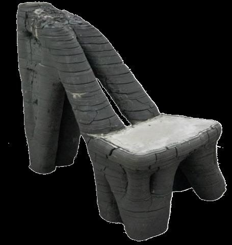
ROBOTIC FABRICATION OF TOPOLOGY OPTIMISED                                       97
              CONCRETE COMPONENTS WITH REUSABLE
                          FORMWORK

4.3. FABRICATION METHOD & SEQUENCE

Our fabrication approach is inspired by slipforming, where a mobile formwork moves
vertically upwards incrementally while concrete being poured in simultaneously. This
method is useful for constructing monolithic structures and has been recently
customised to fabricate geometrically complex structures (Lloret-Fitschi, et. al., 2020).
    For our scenario, we print an adequately thick clay mould that resists the lateral
pressure exerted by the concrete poured at specific intervals during the printing process.
This gives several benefits of: (i) concurrent setting of both concrete and clay, allowing
both materials to stiffen together to support the next segment, enabling larger
cantilevers to be created incrementally; (ii) reducing the drying shrinkage of both
materials as the concrete almost instantly fills the wet clay mould; (iii) ensure that the
poured concrete entirely fills all the gaps of the mould, which is problematic for moulds
with complex geometries.
    The main challenge of such an approach is to identify the appropriate timing of
pouring the concrete into the clay mould during the printing process. In this scenario,
we consider three critical objectives: 1. The neighbouring segments of concrete must
be well connected to ensure structural stability by avoiding delamination at these
regions; 2. The clay printing must finish before the setting of the preceding segment of
concrete; 3. The concrete has to be fast setting so that preceding segments of concrete
no longer exert pressure on the clay mould and can sustain the incoming weight of the
next segment of concrete. Thus, each segment of concrete must be cast before the initial
setting of the former portion and must be given enough time to hydrate and solidify.
    Our concrete mixture is designed to reduce its setting time and be sufficiently stiff
for our application. The ingredients and their quantities are listed in Table 1, with the
mix including: Calcium Sulfoaluminate (CSA), sand (S), water (W), superplasticiser
(Sp), glass fibre with strands of 6 mm (GF6) and 12 mm (GF12) in length, deformer
(D) and Dihydroxysuccinic acid (Da).

                             Table 1. Proportion of the concrete mix.

       Component              CSA      S       W       Sp     GF6       GF12   D     Da
     Amount(g)/Litre          812      988     295     6.5    12        12     0.9   0.5

    Moreover, to guarantee the success of the print, several areas of the mould were
manually supported using foam blocks that were cut to s, small clay chunks or a thin
stick. These were positioned directly under the cantilevering areas with higher than 35-
degree angles, such as under the seat top and at the branches at the back of the chair
seat. This combination of automated and manual methods helped to reduce the chance
of deformations of the clay mould when concrete was added and further sped up the
overall fabrication process. In total, this combination of simultaneous robotic printing
and casting allowed this urban furniture to be completed in a short duration of 5 hours.
98 Y. GUO ET AL.
Figure 7. Fabricating the prototype
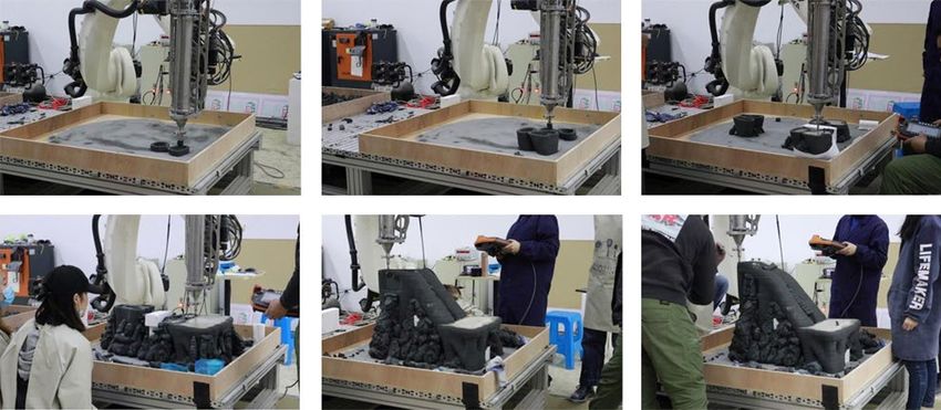
Subsequently, the concrete was left to cure within the clay mould for a total of five
days before demoulding. On the first day, many cracks around the cantilever branches
were observed at the regions where the segments were bonded (Figure 8a). This could
be due to the smaller bonding area per layer due to the smaller sizes of the branches
and larger shifts of printing paths to form the target cantilever angle. As for other areas,
the cracking was distributed evenly in the cross-layer direction and along-layer
direction.
On the final day, the clay mould was removed and recycled without much effort as
the dried clay had already cracked and peeled off, making it easy to remove by hand.
The demoulded clay was then recycled by mixing with water to filter off the concrete
dust and settle as a slurry. The uncontaminated clay can be recycled for the next print
job, closing the loop to this material cycle.
5. Discussion
This paper demonstrates our improved design-to-fabrication workflow to create a
geometrically complex branching concrete urban furniture intended to brace trees
during typhoon weathers. It showcases how our method can fabricate this topology
optimised component with large cantilever angles and overhangs within a short
duration. Such an approach can also facilitate the fabrication of not only structurally
optimised components like our previous truss structure (Wang, et. al., 2019) or ribbed
floor slabs, but also geometrically complex decorative components such as doubly
curved facade panels or bifurcating non-load bearing columns.
Moreover, this approach responds to SDG 12 by considering the entire material
cycle of using clay from extrusion, casting, demoulding to recycling. This closed-loop
material consideration provides ecological benefits by ensuring that the clay material
always returns to the first mould-making step after demoulding. This method contrasts
with typical concrete formwork construction which usually ends up discarding its
formwork or mould materials. Thus, this encourages a sustainable take on how a
sacrificial mould material can be recycled for future prints and minimise waste.ROBOTIC FABRICATION OF TOPOLOGY OPTIMISED 99
CONCRETE COMPONENTS WITH REUSABLE
FORMWORK
Although this prototype uses a largely automated process in its fabrication, there
still are geometric limitations where we used manual procedures. Thus, our future work
aims to investigate how we can fully automate this fabrication process to minimise
human intervention and make the printing and casting steps more efficient.
(a) (b)
Figure 8. The final artifact of the tree support: (a) the clay mould a day after the final
cast (before demoulding); (b) the concrete prototype (after demoulding).
Acknowledgements
This design project was one of many created during an option studio conducted in
collaboration with the Zhejiang University and the Singapore University of
Technology and Design. The prototyping was carried out in the Robotic and AI lab of
the architectural department of Zhejiang University. The conceptual design was created
by Guo Yiyao and Luo Yang with further refinements to the model and printing path
generation implemented by the tutor, Wang Sihan. The fabrication sequence was
planned by Guo Yiyao, Luo Yang, and Zheng Liquan. In addition to the first two
authors, the fabrication process was assisted by several other students in the studio,
namely Zheng Liquan, Chen Xinchang, Huang Jiale, Gu Sijia, Xu Qian, Zhu Yijiang,
and Yufan.
References
Agustí-Juan, I., Müller, F., Hack, N., Wangler, T., and Habert, G. (2017) Potential benefits of
digital fabrication for complex structures: Environmental assessment of a robotically
fabricated concrete wall, Journal of Cleaner Production, vol. 154, 330-340, 06/15 2017,
doi: 10.1016/j.jclepro.2017.04.002.
Akhnoukh, A. K. (2020). Advantages of Contour Crafting in Construction Applications.
Recent Patents on Engineering, 14.
https://doi.org/10.2174/1872212114666200218111631.100 Y. GUO ET AL.
Gramazio, F., Kohler, M., Willmann, J., & Eidgenössische Technische Hochschule Zürich.
Chair of Architecture and Digital Fabrication. (2014). The robotic touch: how robots
change architecture. Park Books.
Hauschild, M. and Karzel, R. (2011). Digital Processes: Planning, Designing, Production.
Birkhäuser. https://doi.org/10.11129/detail.9783034614351.
Kamimura, K., Gardiner, B., Dupont, S., Guyon, D., & Meredieu, C. (2016). Mechanistic and
statistical approaches to predicting wind damage to individual maritime pine (Pinus
pinaster) trees in forests. Canadian Journal of Forest Research, 46(1), 88-100.
https://doi.org/10.1139/cjfr-2015-0237.
Lachemi, M., Hossain, K. M. A., Anagnostopoulos, C., and Sabouni, A. R. (2007)
Application of maturity method to slipforming operations: Performance validation,
Cement and Concrete Composites, vol. 29, no. 4, pp. 290-299.
Lloret-Fritschi, E., Wangler, T., Gebhard, L., Mata-Falcón, J., Mantellato, S., Scotto, F., ... &
Flatt, R. (2020). From smart dynamic casting to a growing family of digital casting
systems. Cement and Concrete Research, 134, 106071.
Mansour, M. A., Rhee, D. M., Newson, T., Peterson, C., & Lombardo, F. T. (2020).
Estimating Wind Damage in Forested Areas Due to Tornadoes. Forests, 12(1), 17.
https://doi.org/10.3390/f12010017.
Neumann, C. J., National Climatic Data Center (U.S, National Hurricane Center (1965-1995,
United States. National Weather Service, & United States. National Environmental
Satellite, Data, And Information Service. (1993). Tropical cyclones of the North Atlantic
Ocean, 1871-1992. National Oceanic And Atmospheric Administration, National Weather
Service, National Environmental Satellite, Data, And Information Service.
Reinhardt, D., Saunders, R., & Burry, J. (2016). Robotic Fabrication in Architecture, Art and
Design 2016. Cham Springer International Publishing.
United Nations. (2022). Build resilient infrastructure, promote inclusive and sustainable
industrialization and foster innovation, Retrieved January 22, 2022, from
https://sdgs.un.org/goals/goal9.
United Nations. (2022). Ensure sustainable consumption and production patterns. Retrieved
January 22, 2022, from https://sdgs.un.org/goals/goal12.
Vantyghem, G., De Corte, W., Shakour, E., & Amir, O. (2020). 3D printing of a post-
tensioned concrete girder designed by topology optimization. Automation in Construction,
112, 103084. https://doi.org/10.1016/j.autcon.2020.103084.
Wang, S.H., Morel, P., Ho, K., & Dritsas. S. (2016). Clay robotics: A hybrid 3D printing
casting process, In Proceedings of the International Conference on Sustainable Smart
Manufacturing (S2M), Lisbon, pp. 83-88.
Wang, S.H., Huang, K.S., Huang, Z.X., Sodano, M., Xu, W.S., Raspall, F. (2019). Fabrication
of Topology Optimized Concrete Components Utilizing 3D Printed Clay Mould, In
Proceedings of the International Association for Shell and Spatial Structures (IASS),
Barcelona.You can also read